Piping Technology & Products designed and manufactured new pipe supports for high-temperature pipelines at an existing power plant in August of 2002. This new design was the product of a customer’s urgent need during an emergency shut-down and the unique pipe support requirements. The original large-bore pipe supports on this high-energy pipeline were not optimally designed for the key operating conditions and as a result, failed to support the pipelines during their thermal movements. The previously supplied OEM pipe supports did not prevent (or insulate) heat transfer from the pipelines to the supporting pipe rack steel. These issues led to the plant shut down due to safety and operational considerations by the client and we were called to help.
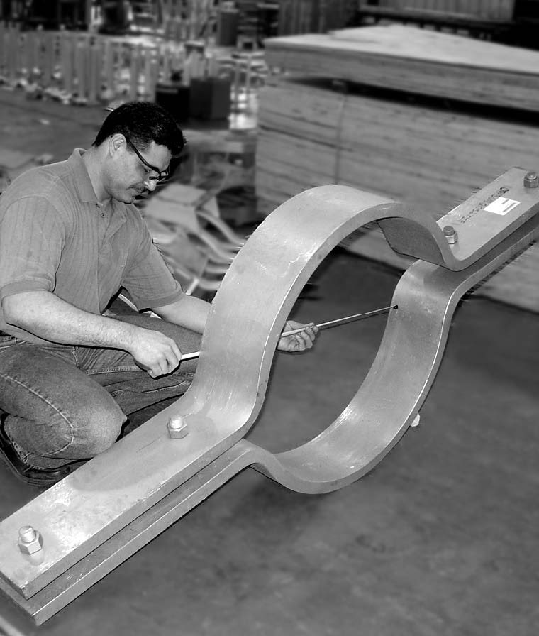
PT&P was called in after the original supports failed again. Upon our field service technicians’ inspection, we recommended a new design brought on by the unique requirements of installation and time constraints. The power plant was in critical condition and needed a specialized minimum downtime “plan-of-action.” PT&P’s engineering and manufacturing teams worked quickly on the new design.
Engineering utilized FEA to both design the plate material and thickness required to support the various loads for the new pipe shoe and calculated the required frictional clamping force for line temperatures ranging from 650°F to 1100°F. The new supports were then manufactured on an expedited basis, supports were on-site for the client in less than 2 weeks from when the PO was placed. Our field service team traveled to the plant location and removed the failed OEM supports, and installed the newly designed supports which are still in operation today, and have replaced other OEM supports throughout their facilities nationwide.
Because the elevations of all the piping were fixed, PT&P had to develop a pipe support design that would dissipate heat and protect the PTFE 25% glass-filled slide plates (installed beneath the pipe shoe to reduce friction) from thermal damage by utilizing a design concept called “Natural Draft Air Cooling.” Natural Draft Air Cooling has several advantages over previous designs:
Since the insulation does not carry any mechanical load with the new design, insulation material can be chosen solely based on its thermal properties. In this particular case, cyclic loading had caused insulation failure in the previous design. This problem was now alleviated.
The new support provides effective restraint for multiple components of loads, X, Y, Z, Rotational, and Translational dependent on the location. In particular, Axial and Torsional loads are readily accommodated. These types of loads usually present difficulties for supports that rely on insulation to support a given load.
The newly designed supports are easily installed in the field by attaching them to the pipe with bolted pipe clamps. Thus, there is no field welding.
PT&P REF. ORIGINAL POST 10102017 / Technical Bulletin 2009
Why PT&P Spring Supports
PT&P is setup to offer our customers the absolute best value in Spring Supports. The following are key factors that differentiate PT&P Spring Supports:
Global Leadership – PT&P has been providing spring supports for over 40 years and has millions of Spring Supports currently in service. We are the standard used by many EPCs and Operating Plants globally.
Superior Engineering and Support – PT&P is the only major Engineered Pipe Support provider that started as a Pipe Stress Engineering company. This one of the reasons why we are the only major global provider of both engineered pipe supports and expansion joints. When you order from PT&P, you not only get our product, but you also get service from one of the world’s leading Pipe Stress Engineering firms. We can assist in product selection, installation advice, and maintenance advice. We conduct 100+ individualized Technical Training sessions each year for EPCs and Operating Plants.
Superior Manufacturing – PT&P manufactures to a higher standard than other Engineered Pipe Support providers. One of the reasons we are the only major manufacturer of Expansion Joints and Pipe Supports is that the skill level required to manufacture Expansion Joints is distinctly higher than Pipe Supports. For example, we TIG weld thin gauge Hastelloy and other superalloys every day in our Expansion Joint production. Beyond the superior skills we keep on staff, PT&P has a unique ability to service short lead-time orders. Some of these are in as little as 12 hours. Our unique manufacturing approach is explained on this link.
Superior Quality – we have seen many Spring Supports in the field that have been highly “cost-engineered’. The easiest way to look for this is to check the support for the use of thin gauge material (you can just tap on it). This is often accompanied by a painted finish which must be used because galvanizing, while far superior (paint vs galvanized) for most applications, would warp thin gauge material.PT&P has not gone through this cycle of cost-engineering. If you check PT&P spring support, you will quickly see we use thicker gauge material with a standard galvanized finish that is designed to last for the long term and survive in the most difficult environments.
Unparalleled Customization Options – because PT&P has set up it’s manufacturing to easily accommodate customization and has advanced manufacturing skills that other spring support manufacturers lack, we can offer the broadest range of options. These include
Variable Springs with Red Oxide Primer Designed for a Furnace Application
Dimensions
The size can be optimized to specific dimension requirements, and customized to fit in restricted spacing.
Nano Constant – The Worlds Only Size-Optimized Constant Spring
Custom “Mini” Big Ton Spring Supports Designed for a Centrifugal Fan in a Chemical Refinery
Load
We can supply spring supports with custom load capabilities of
800,000 lb. + loads.
Load Adjustment
Standard is +/- 10%, but we can customize up to +/- 60% Load Adjustment)
600,000 lb. Load Mega Ton Spring Support with Bronzphite® Slide Plates
187,393 lb. Load Big Ton Constants with Bronzphite® Slide Plates
Travel
Standard is +/- 10%, but we can customize up to +/- 60% Load Adjustment)
Travel Stops
We can provide wire or chained travel stops.
Constant Spring Support w/ 46” of Movement
Variable Spring Supports with Chained Travel Stops
Sensors for Remote Monitoring
We can provide sensors on spring supports to monitor the conditions remotely, and give warning alerts whenever a support does not perform as it should.
Unparalleled Customization from Unmatched Manufacturing Capabilities
PT&P has developed a unique approach to its manufacturing operation that produces the broadest set of customization options with minimal impact to delivery timeframes. Most producers operate as smaller scale steel fabricators or highly standardized mass production organizations. PT&P is the only organization that is set up for both scales with over 500 production employees, customization capabilities, and artisan manufacturing skills. For example, PT&P is the only Major Global Supplier of both Expansion Joints and Engineered Pipe Supports. This unmatched manufacturing technique was achieved through proprietary systems, a highly engineered approach to manufacturing, and incorporating 10+ Industrial Engineers in the production operation.
Manufacturing Approach for Pipe Support/Expansion Joint Manufacturers
G10 Micarta® can be very cost-effective insulation as compared to Polyurethane foam (PUF), especially for medium and large shoes. It offers tremendous benefits at various stages of a project, including but not limited to:
Procurement
Installation
Handling, transportation, and storage
Plant Maintenance
Cryogenic Pipe Supports with Micarta® Insulation for an LNG Plant
Major Advantage of G10 Micarta® Supports for Procurement
G10 Micarta® supports involve fewer steps to manufacture, allowing for a quicker fabrication turnaround. It takes 2-3 weeks less on average than PUF supports for delivery. This enables the ability to catch up on deadlines and reduce downtime.
G10 Micarta® shoes cost less than PUF shoes of the same size, meaning Low Capital Expenses:
Advantages of G10 Micarta® Supports During Construction/Installation
G10 shoes can be sent to the pipe fabricator and can weld directly to the pipe spool, meaning there is minimal installation in the field. It takes 3-5 hours to install a PUF shoe in-field, depending on the size. G10 Micarta® shoes save that FIELD installation time.
Micarta® Block Assemblies for Placement Beneath a Saddle Support of a Vessel
Shop welding of G10 Micarta® shoes is much cheaper. As G10 shoes are weld to pipe spool at the fabricator’s shop, they can be inspected and tested in the shop; no inspection and testing in the field. More cost savings as inspection and testing is done at cheaper rates at pipe spool fabricator facilities rather than in the field.
As G10 Micarta® shoes are handled along with the pipe spools, there are fewer chances of missing supports in the field. Less OS&Ds to worry about for both the client and supplier.
Major Advantage of G10 Micarta® Supports while Handling, Transportation & Storage
G10 Micarta® supports are less fragile than PUF, making the handling, transportation, and storage of G10 to be trouble-free. No special packaging required, saving the time & the cost of special crating. Stronger G10 supports reduce the chances of accidental damage, thereby the need to re-fabricate the support.
Cryogenic Pipe Supports with Micarta® G10 Insulation, and Axial Stops for an LNG Facility
G10 Micarta® supports have insignificant water/moisture absorption rate, this means:
No structural deterioration in adverse weather, especially in the wake of heavy rain and storms. PUF deteriorates in wet weather or humid climates
Better life of the support
Less maintenance and more saving
Testing of G10 Micarta® Support
Comparison of G10 Micarta® vs. PUF from previous test reports:
Time-dependent temperature variations at the stated locations using G-10 Micarta®.
(i) T-pipe; (ii) T-top; (iii) T- ambient; (iv) T-Bottom, (v) T-BOS.
Time-dependent temperature variations at the stated locations using Polyurethane.
(i) T-pipe; (ii) T-top; (iii) T- ambient; (iv) T-Bottom, (v) T-BOS.
Preventative Maintenance Best Practices: Replace Spring Support Audits with Pipe Stress Audits
Image Source: By David Wright, CC BY-SA 2.0, https://commons.wikimedia.org/w/index.php?curid=8563768
Piping Technology and Products has a unique perspective on best practices in preventative maintenance. PT&P has a database built from over 1,000 audits performed in 41 countries. PT&P also has experience from over 3 Million pipe supports and expansion joints currently in service.
The following is a summary of the strategies PT&P sees at operating plants:
Only fix spring supports when something is wrong (e.g. vibration, leaks, …)
Perform regular inspection and replace damaged spring supports
Periodically return piping line to its original design specification and/or set new design standard if the design has changed
The design of the piping system is a major part of the engineering of an operating plant build. On average, piping constitutes 40-48% of the engineering hours in a new refinery. The challenge facing piping engineers is rotating equipment locations and process design are defined and the piping engineers must make the piping system fit within the designated space while dealing with thermal stress, proper flow, and allowable loads for all equipment. With temperatures in high energy lines often well over 1,000 degrees, this can be very challenging. The following are some of the goals of pipe stress engineering and the placement of spring supports and expansion joints in the piping system:
Ensure stress at the interface to moving equipment is below maximum allowable loads
Minimize turbulent flow through the piping system
Ensure the longevity of piping system components
Figure 1 – Pipe Support and Expansion Joint Maintenance Strategy *Shows the strategies that PT&P commonly sees at different operating plants:
Strategy
Pros
Cons
Fix When Broken
Maximize short term cash flow
Potentially moves financial impact from Opex to Capex
Limits overspending on preventative maintenance
Likely leads to allowable stress being beyond max for some moving equipment
Will lead to maintenance issues with moving equipment
Insures broken spring support are replaced prior to causing issues
Does not ensure the proper functioning of each spring without adjusting Spring Supports which are out of position
Periodically Return to Original Design Specification (System Level Focus)
Ensures the system is brought back to original design minimizing strain on moving equipment
Minimizes stress on the piping system
Higher short term expense
The business case can be challenging due to the medium/long term nature of savings
Potentially more Opex vs Capex
Minimizes risk of an unplanned outage
PT&P has seen many examples of each of the strategies above. Typically, the strategy taken at an individual plant is closely related to overall operating philosophy of the organization, including finance. However, we also speak to a number of organizations who have placed an emphasis on preventative maintenance but are not sure of the best practices for the engineered pipe supports and expansion joints.
Appendix A shows an example of a program PT&P executed March of this year on a turnaround. For preventative maintenance, best practice is to not just focus on the health of the piping system components, but on the health of the overall piping system. The following are some of the issues that PT&P has found that cause system level issues:
Spring Support Failure Impact – the failure of a spring support will impact other supports and cause them to possibly fail as they attempt to take on the additional load of the failed spring
Damage to Piping or Rigid Supports Changes Elevation of Spring Supports – a variety of issues can cause the piping to undergo strain, which causes deformation. This will cause a change of elevation or distance from the pipe support to the pipe and impact the load setting and connections to other equipment
Improper Travel Stop Management – if travel stops are not removed, the spring supports are essentially a rigid support, and the load can be redistributed among the spring supports on the same line in a way that is not consistent with the original design
Improper Initial Installation – one of the most common issues PT&P finds in its audits is that engineered supports are improperly installed during initial installation
By the time a plant reaches 10+ years of age, PT&P’s experience is that most plants have encountered one or more of the issues above. For this reason, it is essential to take an approach of resetting the line to the original design specification. Best practices for performing a “reset to design specification” are the following:
Hot and Cold Audit – required to understand the range of movement
View of Functioning of Springs/Expansion Joints Across Line – the view of how a spring is functioning can be highly dependent on whether there are many failed supports on the line versus just one
Plan for Adjustments and Replacements – the overall plan for a turnaround must be comprehensive in terms of adjustments
Proper Management of Travel Stops – we have found tremendous confusion on the proper timing for placement of travel stops; if this is not done correctly, in many cases it is not possible to reset the line to the original design specification
Repair Rigid Support Issues – a common issue we have run across is a damaged or removed pipe shoe or saddle resulting in the piping sitting on the supporting pipe rack
Assess Elevation Changes – changes in elevation due to changes or deformation of piping can cause a spring support to be out of position; this issue should be addressed as an issue with the line rather than the spring support
Identify Design Changes – PT&P sees many situations where there have been alterations to the line, such as new equipment without an update of the stress analysis; the best approach is to redo the stress analysis; however, the budget or time constraints may require a quick and dirty approach such as weighing the line
Adjust in Real Time as Needed – Given all of the issues above, resetting a piping line to design specification takes real-time decision making during an audit
The challenge with this approach to preventative maintenance is that it takes a much deeper level of expertise than a component level inspection. PT&P’s experience is that even the ability to operate a pipe stress modeling software program such as CAESAR is far different than a pragmatic understanding of the proper functioning of all the elements of the piping line. Many personnel and firms supporting piping system maintenance are challenged with managing a broad range of equipment at an operating plant, and this can make it difficult to have the depth in pipe stress that may be required to properly execute a system level audit and execute a plant to return the piping system to the original design specification.
The sole purpose of performing audits is to maintain the piping system and equipment to remain in the proper condition. Therefore, the system level (pipe stress audit) that considers the physical condition of the system, along with the spring supports system should be preferred. As mentioned earlier, the component level audit is an important part of the system level which if put together with other system and/or deformation assessment can give the overall picture of the system and finally a better direction for the proper maintenance.
An Example of System Level Repair Work: Spring Supports Issues on Manifold of a Heater
PT&P performed an installed inspection on all the springs supporting a manifold of a heater. The installed (or ”cold”) condition inspection showed that most of the supports were operating properly. However, after performing a second inspection in the operating (or ”hot”) condition, it was concluded that most of the spring supports did not show any signs of movement. This issue was brought up with the customer, and it was determined they were having some issues with the heater tubing affecting the efficiency.
During Cold Inspection
During Hot Inspection
Since this issue needed to be addressed to prevent any failures in the future, all the supports from the manifold were assessed and concluded that there is a need for system level repair. Therefore, on a 2019 turnaround, all the spring supports of the manifold were replaced.
The following pictures show that the new supports are moving as designed and system-wide repair was indeed required.
During Cold Inspection (March 2019)
During Hot Inspection (May 2019)
5 Spring Supports from a Manifold were Replaced During a 2019 Turnaround
All together 35 spring supports on manifolds were replaced due to failure of previous spring supports.
Appendix A: Turnaround plan and Execution for a Major Refinery
A.
Pipe Supports
•
10 Units
•
> 600 Spring Supports
•
12% Adjusted
•
14% Replaced
B.
Expansion Joint Installation Supervision
•
36 Expansion Joints Replaced
Work Scope:
Pipe supports inspection during the installed or cold condition
Supervision on adjustment of the spring supports
Installation of spring supports as per in Table A for the period of 30 days
In addition to the above, PT&P provided a supervisor (Expansion Joint Technical Expert) to supervise the installation of expansion joints.
Planning:
PT&P provided two engineers about a year before the turnaround to perform the operating inspection of the spring supports while a cold inspection was done by PT&P in the previous turnaround. All these inspected supports were documented in a report and the conditions were categorized as good, replacement or adjustment required.
Pre-Turnaround:
Based on the location provided in the inspection report, and constant communication between PT&P engineers and turnaround co-coordinators, the location where the scaffold is to be built was pre-planned.
The materials were purchased a few months before the turnaround. All the required safety training, drug tests, background checks were done prior to the turnaround date.
During Turnaround:
Out of 10 units, 4 units were “shut down” upon arrival at the site. PT&P engineers performed a quick walk-down on all the spring supports in the units to see if there were any new issues since the last inspection which required immediate attention. This gave enough time to order the materials and necessary hardware.
After the quick inspection, PT&P worked with a few client technicians on two different units. The adjustment and installation work on the two units were done concurrently.
Once those units were completed, PT&P engineers were mobilized to other units. There were a few new discoveries where PT&P engineers ordered materials for adjustment and replacement. Within a couple of days, PT&P managed to supply the parts (shipped through hot shot) and resolve the issues.
There were five times, PT&P provided the materials during the period of turnaround within 48 hours. It was very convenient to have engineers supervising the installation and repair as it allowed for design and/or engineering changes to be made on the spot.
In addition to the pre-planned turnaround work, PT&P engineers assisted, on several occasions, to help resolve issues such as bent struts, check the condition of counterweights (old style), some new expansion work which included the addition of new pipe supports.
Pictures of replaced cans:
Cracked Spring Support
After Replacement
Bent Rod During Turnaround Work
After Repair
During Follow-up Hot Inspection
The rod was bent during the turnaround because the contractor working did not reinstall the travel stop while working with the line. The support should have been locked and disengage from the system for this specific work on the pipe coming out of the reactor. The line seemed to have higher movement than anticipated during the turnaround work. This was the second time the rod was bent. PT&P engineers, which were on site for other spring supports work, were contacted immediately. Less than an hour, PT&P field service technicians went and assessed the condition and suggested an improved, robust design. The materials were purchased as per PT&P engineers’ recommendation. Since the order came directly from the field from a PT&P employee, the approval and manufacturing process was smooth and quick. Within a couple of days, the materials arrived and were successfully installed. Everything operated correctly during the follow-up hot inspection.
For Expansion Joints (EJ):
PT&P supervisor was on site the entire time helping the contractor remove and INSTALL the new expansion joints. Almost all of the CLIENT contractor workers were inexperienced or very limited experience working with expansion joints.
PT&P supervisor gave a quick training about removing and installing the new EJs. They also pointed out the importance of being sensitive towards the EJ fabric since one small improper cut could damage the belt.
PT&P supervisor assisted the contractor with the proper marking of “backing bar” while removing the old EJ. He inspected the condition of the joint and guided contractors to efficiently install the new expansion joint. He also showed the proper way to splice the fabric materials to complete the EJ Installation.
PT&P Mass Customized Manufacturing
PT&P’s Mass Customized Manufacturing – How to Make an Elephant Dance
Examples of Mass Customization include:
Amazon Web Services – Amazon revolutionized the IT Industry with its web services which offered customers unprecedented computing on demand with a vast array of value-added services.
Nike Customized Shoes
Harley Davidson
Wolverine Shoes
Brooks Brothers
Pipe Support and Expansion Joint Manufacturing
One of the major challenges faced by many Pipe Support and Expansion Joint manufacturers is trying to serve Major EPCs, Operating Plants, and Mechanical Contractors. The following is a summary of the needs of these different customer groups:
Figure 1 – Customer Requirements for Different Segments of Customers
Major EPC
Mechanical Contractor
Operating Plan
Typical Project
New Plant Build
Small Plant Modification
Maintenance in Turnaround
Volume Requirements
Large
Small/Medium
Small
Lead Time for Products
Long
Short/Medium
Short/Medium
Engineering Support from Vendor
Low
Medium
Medium/High
Customization Requirements
Low
Medium
Medium
Customer Operating Time Horizon
Turnover of Plant in 1 yr.
Varies
10+ Years
The challenge for this mix of customers is that the differences in customer needs’ leads to a fundamental set of choices in terms of manufacturing configuration. Figure 2 shows the choices we see in the marketplace. As can be seen from the table, the big difference is in the target customer for which the operation was designed. The following is a summary of Manufacturing Strategies we have seen:
Steel Fabricator – this type of company is typically founded by someone who is skilled at steel fabrication and is a smaller operation with a group of reasonably skilled fabricators. This type of firm tends to be good at customization but struggles at scale. It is also typically pushing for any work it can get with the goal of ultimately attaining scale.
Mass Production – almost all of the larger-scale firms in the industry fall into this category. For a steel fabricator, a transformation into mass production is a natural outcome of serving the Major EPCs. The volumes seen from major EPCs can dwarf other segments. In addition, major EPCs tend to allocate far more resources to purchasing and vendor management than other customers (Purchasing is actually the middle man). As a result, we have seen most major players migrate aggressively to this setup.
PT&P Mass Customization – PT&P’s approach is unique in the Pipe Support and Expansion Joint market. The fundamental reason for this is that our DNA is not Steel Fabrication. PT&P was founded as a Pipe Stress Engineering company and migrated into manufacturing over time from the encouragement of our customers. We grew the business from serving operating plants to partnering with Major EPCs but never left our origins of serving operating plants. Fundamentally, serving the tremendously varying needs of different customers has become an engineering problem to be solved for PT&P.
Figure 2 – Manufacturing Approach for Pipe Support / Expansion Joint Manufacturers
Steel Fabricator (Owner/Operator)
Mass Production
PT&P Mass Customization
Machinery
Simple
Scale
Scale and Artisan
Advanced Skills (e.g. TIG welding Inconel)
Varies
Limited
Yes
Systems
Limited
For Mass Production
Advanced Systems allow Management of Complexity
Customization/Flexibility
High
Low
High
Short Turnaround
Yes
No
Yes
Scale
Low
High
High
Outsourced Offshore
No
Yes
No
Engineering Knowledge
Low
Medium
High
Ability to Manage Contamination Across Materials
?
No
Yes
Breadth of Product Line
Medium
Low/Medium
Large
Target Customer
?
Major EPCs
All
How Does PT&P Manage Mass Customization?
Most companies do not do mass customization because it is very, very difficult and really takes an engineering, not steel fabrication mindset. The following are some of the key elements that allow PT&P to offer Mass Customization:
Scale – PT&P has over 500 production employees and 70 Design Engineers at our Houston Headquarters location. With 40+ years in business, we have developed the reputation required to be a scale operator in terms of the quality of our products and reputation within every customer segment.
Industrial Engineering – PT&P has 10 Industrial Engineers in our manufacturing operation with most having a Master Degree. This provides both the intelligence to manage a high degree of complexity as well as a mindset of making continual process improvements.
Systems – one of the keys to our ability to uniquely manage mass customization is our systems. We have evaluated many off the shelf systems including JobBOSS, E2, Global Shop Solutions, Fishbowl, and many more. While all have major capabilities, none were a good fit for the scale and complexity of our operation. We have developed a set of systems that give us the reporting and insights required for managing Mass Customization.
Centralized Scheduling for 50+ Operations – The key to the operation is the ability to schedule down to the part level in over 50 individual operations. Jobs, Items, and Parts are analyzed on a variety of factors including lead time, natural “clubbing” between different jobs, material, complexity, run time, the status of other parts in the job or item, etc. This leads to a daily schedule for every operation that communicated to every lead and operator.
Manage By Job – every job is easily viewable with a detailed view of status. Figure 3 shows an example of the visibility we have into every order. This is also the same visibility that customers have via the customer portal.
Figure 3 – Sample Job Status Available via Customer Portal
Manage By Critical Path Operation – PT&P can view backlog, average daily production, and staffing by 50+ detailed operations across all of the production. This allows us to constantly identify bottlenecks and move resources to the most backlogged operation.
Manage By Short Lead Time Orders – PT&P maintains an entire section of production for short lead-time, smaller volume orders. These orders are delivered within 2 weeks and often times within 48 hours.
Manage By Product – Because of our scale, we maintain a specialized area of production for a number of products including Expansion Joints, Variables, Constants, Struts, Sway Braces, Pre-Insulated Supports, and Slide Plates. We are able to assess production by product to see how each of these operations are performing.
Work Instructions Software – One of the most difficult aspects of mass customization is how to deal with “tribal” knowledge. In a steel fabrication operation, high degrees of individual knowledge is relied upon for production. In a Mass Production operation, flexibility is eliminated in order to reduce dependence on specialized individual knowledge. PT&P has taken a different approach. It encapsulates complex operations into its Work Instructions Software. The challenge with complex operations is all of the “edge” cases that require “non-intuitive” procedures. For example on our Automatic Long Seam welder in the Expansion Joint operation, sheet metal must be measured as the mill tolerance is not tight enough to specify the program to be used on the welder (e.g. there is a different program for 18 Gauge vs 17 Gauge).
Figure 4 – Sample Work Instructions Software
Partnerships with Houston Colleges – PT&P has established partnerships with key colleges throughout Houston. This allows us to maintain even the most scarce skills within our production operation. PT&P has an unusually deep commitment to learning and education with our founder serving on the Board of Regents of the University of Houston.
Automation – PT&P’s scale has allowed it to invest in automation which both increases volume and quality. Automated Machinery includes CNC Plasmas, CNC Rolls, CNC Mills, Robotic Welding, Automatic Saws, Automatic Long Seam Welding, and High Volume Foam Pouring.
Product Specialization – PT&P uses scale across products where appropriate but also has specialized products for some aspects of key products including Expansion Joints, Variables, Constants, Struts, Sway Braces, Snubbers, and Pre-Insulated Supports.
Growth Plans for Key Skills – anyone with a welding background could tell you that welding carbon steel plate is a piece of cake compared to welding thin gauge Inconel. We start our welders working with carbon steel plate and structure and allow those who show the desire and skills to grow into the higher-skilled areas of welding.
Management of Material Contamination – PT&P has specific procedures in place to ensure the material remains separated to avoid contamination such as Carbon Steel contaminating Stainless. The combination of material contamination management and skill level required for thin gauge Super Alloys is one of the major reasons PT&P is the ONLY major Pipe Support manufacturer that also manufactures Expansion Joints.
The Benefit for our Customers: Always the Best Solution
Mass Production companies and Steel Fabricators will by their nature be limited in the solutions they can offer. This means they will be tempted to “force fit” customers into their capabilities. The following are just some of the options that PT&P offers with ALL of its products:
Schedule – approximately 15% of PT&P production is for short lead-time orders in 2 weeks or less with some of these even being less than 24 hours from order to delivery.
Material/Unusual Environments – one of the biggest advantages PT&P offers is that it has engineering and production skills to work with almost any type of steel or alloy. In our Expansion Joint operation, we work daily with Stainless Steel and Super Alloys including Monel 400, Inconel, Hastelloy, and Incoloy. For example, a customer recently asked us about a Paint over Galvanizing finish for plant struggling with a Caustic Environment and we educated them on the range of options offered by PT&P including an all stainless option along with the ability to even move to Super Alloys. In this case, the customer was supporting Nickel 200 piping which costs over $10/pound with a Variable made of carbon steel which costs under $1 per pound and was failing every 2-3 years.
Figure 5 – Monel 400 Clamps
Space Constraints/Size – PT&P can engineer to any dimensions feasible including the world’s smallest Constant Spring Hanger Designs. If there are challenging space requirements, PT&P can engineer the most efficient solution possible. Figure 6 shows a Nano Constant Design for 750-pound load and 77″ of movement. The overall dimensions of the Frame and Cam are 227″ x 7″ x 9-15/167″. This means PT&P is supporting over 700 pounds and 7″ of movement in with a Constant Hanger that is only 0.89 Cubic Feet!
Figure 6 – Nano Constant Design for 750 Pound Load and 7″ Movement
Challenging Load Requirements – PT&P invented the Big Ton in 1980 which placed springs in series in order to accommodate larger loads. We have engineered solutions up to 1M pounds of load including complete FEA analysis.
Figure 6 – PT&P 600,000 lb. Load Mega Ton Spring Support with Bronzphite® Slide Plates
Movement – PT&P has engineered designs across its products for larger more challenging movement requirements. For example, Figure 5 shows a Constant that was designed and produced to support 46″ of movement for a Geothermal plant in Hawaii.
Figure 7 – Constant Load Hanger for 46″ of Movement
Precision CAESAR Stress Audit Using Laser Scanning
One common issue we see across our 1,000+ audits of operating plants is that mid and long-term maintenance issues are often sometimes created during initial plant construction. The issue is that construction is a very complex process with many, many opportunities for error. Anyone who has ever visited a laydown yard is certainly familiar with this issue.
Figure 1- Laydown Yard Photos
Structural Supports in Laydown Yard
Structural Supports, Elbows, and Pipe in Laydown Yard
The following are a list of some of the issues that can occur:
Improperly placed pipe supports
Suppliers errors
Improperly installed supports
Design errors
Incorrect material installed
The current process is for a walk-down to take place to catch as many of these errors as possible. The quality of this process is highly dependent on the knowledge and experience of those doing the walk down. However, even the best engineers are likely to miss something when covering the scale of a Refinery or Power Plant.
Piping Technology & Products has been at the forefront of using the latest technologies to provide better audit capabilities. In particular, we have been looking at how Laser Scanning can be used in the construction and maintenance of Industrial Piping Systems. Attached is a prior article on the growth of the Laser Scanning technology and why we believe it is now on Moore’s Law pace in terms of price/performance improvements due to large investments being made in LIDAR.
The pipelines which are most challenging to design are the High Energy and Critical Lines. These lines are typically designed using CAESAR software to design and model the performance of the line when in operation. If during the initial start-up of the plant, the line does not behave as modeled in CAESAR, there is likely to be some issue that should be resolved for the short, medium or long-term health of the plant.
PT&P offers a service that compares a laser scan of a line both in operation and in the installed mode with the CAESAR model leveraging a new software tool designed to greatly facilitate this analysis. The analysis provides a detailed comparison of the CAESAR model with the as-built drawing from the laser scan. This includes the following:
Accurate placement of the supports – the as-built and CAESAR model is overlaid allowing for a precision check of support placements
Accurate placement of the Piping in the Cold position
Measuring deflection from a base point in the model versus the as-built
Figure 2 – CAESAR Model and Piping Laser Scan
CAESAR Model
Piping Laser Scan
If there are variations from the as-built to the Caesar model, PT&P can diagnose the issues by:
Checking placement of all elements when the line is not hot
Recreating the as-built by modifying the CAESAR model-based PT&P experience (e.g. a spring with travel stop not pulled)
Checking the temperature of the line versus design specification
Establishing the Baseline
With a validated CAESAR model, ongoing audits can be done by continuing the same comparison to the CAESAR model periodically. In addition, as changes are made to the plant, PT&P would recommend an update to the CAESAR model to ensure the proper functioning of the line and acceptable stress being placed on moving equipment.
PT&P offers highly cost-effective services for Pipe Stress Analysis and Laser Scanning. If you would like to discuss this further, call and speak with one of our expert engineers at 713-731-0030.
Thermoplastic Isolator (TPI) – Technical Information
Thermoplastic isolators provide optimum support and eliminate pipe contact with the supporting steel.
Moisture/water can be trapped between the pipe and support, which can initiate corrosion of the pipe
In addition, when TPI is placed between the pipe and the supporting structural steel, it can prevent cathodic reaction
Iron + Water + Oxygen = Rust ➞ Corrosion
Piping Technology & Products can fabricate TPI designed for use with u-bolts. Our u-bolts, have a hot-dipped galvanized finish and are coated with Polyshrink. The Polyshrink acts as a barrier between the u-bolt and the pipe to prevent corrosion, and it also adds protection.
TPI Pipe (angle view)
TPI Pipe (front view)
Benefits of Thermoplastic Isolator (TPI):
TPI has a very high compressive strength
It is subject to very little “creep” over the period of time
TPI is easy to fabricate
Cutting and drilling holes can be easily done
Easy to Install
Very economical when compared to the leading competitor
It can be used with different types of pipe supports
U-Bolt with TPI
Installation of TPI:
TPI can be placed or attached to structural steel by three different methods.
Self-tapping screw or bolting
Double-sided adhesive tape
With u-bolt
Adjustable Pipe Supports with U-Bolt and TPI
Common Industry Application:
Petrochemical plants
Refineries
LNG plants
Offshore platforms
Wastewater plants
Parking garage
Marine pipelines
Types of TPI:
There is a total of 3 different types of TPI available based on thermal properties.
TPI White – Maximum Service Temperature 181°F
TPI Amber – Maximum Service Temperature 340°F
TPI Tan – Maximum Service Temperature 480°F
TPI (Thermoplastic Isolator): Properties & Various Grades
TPI White
TPI Amber
TPI Tan
Property Value
ASTM Test
Imperial
Imperial
Imperial
Density
D792
0.0516 lb/in3
0.0458 lb/in3
0.047 lb/in3
Tensile Strength
D638
11,000 psi
17,000 psi
16,000 psi
Tensile Modulus of Elasticity
D638
450 ksi
500 ksi
630 ksi
Elongation (At Break)
D638
30%
60%
40%
Flexural Modulus of Elasticity
D790
450 ksi
500 ksi
600 ksi
Flexural Strength
D790
13 ksi
20 ksi
25 ksi
Compressive Stress
D695
16 ksi
22 ksi
20 ksi
Coefficient of Friction
QTM 55007
0.25
0.42
0.32
IZOD Impact (Notched)
D256
1 ft-lb/in
0.5 ft-lb/in
0.6 ft-lb/in
Rockwell Hardness
D785
M 88
M 115
M 105
Maximum Service Temperature
(Long Term)
181ºF
340ºF
480ºF
Melting Point
D3418
347ºF
410ºF
644ºF
Coefficient of Linear Expansion
E831
47 µin/in/ºF
31 µin/in/ºF
-
Flammability Rating
UL94
HB
V-0
V--0
Electric Strength
D149
450 V/mil
830 V/mil
480 V/mil
Key Factors in choosing PT&P’s Thermoplastic Isolator over Competitors:
All suppliers of plastic components for these types of supports, purchase raw materials from some of the same sources
PT&P’s TPI is equivalent to competitors, but the price of TPI is much lower
In addition, TPI can be tested in any independent lab
Comparison between PT&P’s TPI White VS Leading Competitor
Property Value
ASTM Test
TPI - White
Competitor
Density
D792
0.0516 lb/in3
0.0509 lb/in3
Tensile Strength
D638
11,000 psi
9,400 psi
Tensile Modulus of Elasticity
D638
450 ksi
380 ksi
Elongation (At Break)
D638
0.3
30-60%
Flexural Modulus of Elasticity
D790
450 ksi
400 ksi
Flexural Strength
D790
13 ksi
13 ksi
Compressive Stress
D695
16 ksi
15 ksi
Coefficient of Friction
QTM 55007
0.25
0.25
IZOD Impact (Notched)
D256
1 ft-lb/in
1 ft-lb/in
Rockwell Hardness
D785
M 88
M 88
Maximum Service Temperature
(Long Term)
181ºF
181ºF
Melting Point
D3418
347ºF
329ºF
Coefficient of Linear Expansion
E831
47 µin/in/ºF
54 µin/in/ºF
Heat Deflection Temperature, 264 psi
D648
250ºF
220ºF
Flammability Rating
UL94
HB
HB
Electric Strength
D149
450 V/mil
420 V/mil
Result from above comparison, both products are equivalent
Comparison between PT&P’s TPI Amber VS Leading Competitor
Property Value
ASTM Test
TPI – Amber
Competitor
Density
D792
0.0485 lb/in3
0.0462 lb/in3
Tensile Strength
D638
17,000 psi
16,500 psi
Tensile Modulus of Elasticity
D638
500 ksi
500 ksi
Elongation (At Break)
D638
0.6
30-60%
Flexural Modulus of Elasticity
D790
500 ksi
500 ksi
Flexural Strength
D790
20 ksi
20 ksi
Compressive Stress
D695
22 ksi
22 ksi
Coefficient of Friction
QTM 55007
0.42
0.42
IZOD Impact (Notched)
D256
0.5 ft-lb/in
0.5 ft-lb/in
Rockwell Hardness
D785
M 115
M 112
Maximum Service Temperature
(Long Term)
340ºF
340ºF
Melting Point
D3418
410ºF
410ºF
Coefficient of Linear Expansion
E831
31 µin/in/ºF
31 µin/in/ºF
Heat Deflection Temperature, 264 psi
D648
400ºF
400ºF
Flammability Rating
UL94
V-0
V-0
Electric Strength
D149
830 V/mil
830 V/mil
Result from above comparison, both products are equivalent.
Comparison between PT&P’s TPI Tan VS Leading Competitor
Property Value
ASTM Test
TPI - Tan
Competitor
Density
D792
0.047 lb/in3
0.047 lb/in3
Tensile Strength
D638
16 ksi
16 ksi
Tensile Modulus of Elasticity
D638
630 ksi
500 ksi
Elongation (At Break)
D638
0.4
0.2
Flexural Modulus of Elasticity
D790
600 ksi
1000 ksi
Flexural Strength
D790
25 ksi
25 ksi
Compressive Stress
D695
20 ksi
20 ksi
Coefficient of Friction
QTM 55007
0.32
0.4
IZOD Impact (Notched)
D256
0.6 ft-lb/in
1.0 ft-lb/in
Rockwell Hardness
D785
M 105
M103
Maximum Service temperature
(Long Term)
480ºF
480ºF
Melting Point
D3418
644ºF
644ºF
Coefficient of Linear Expansion
E831
-
-
Heat Deflection Temperature, 264 psi
D648
320ºF
320ºF
Flammability Rating
UL94
V--0
V--0
Electric Strength
D149
480 V/mil-
480 V/mil-
Result from above comparison, both products are equivalent.
Hot-Dip Galvanizing (Substance) VS Powder Coat or Paint (Style)
One of the most surprising issues PT&P has run into in its 1000+ audits of operating plants is corrosion due to the use of Paint or Powder Coat Systems for corrosion protection. As with most things in life, you can not have your cake and eat it too. Paint can be very attractive.
However, the attractiveness comes at a price…
Figure 1 – Pictures of New Galvanized Pipe and Painted Steel Pipe
Figure 2 – Pictures of 25-Year-Old HDG Support VS. 8-Year-Old Painted Support
PT&P Hot-dipped Galvanized Support
25 Years In-Service in Dubai – Salt Air from
Persian Gulf – 100 Sandstorms per Year
NON-PT&P Painted Support
8 Years In-Service in Texas
Salt Air From Gulf Coast
The other primary advantage of paint is that it works better with very thin gauge steel. Thin gauge steel will warp under the heat of the hot-dip galvanizing process. Obviously, the combination of thin gauge steel and paint for corrosion resistance will lead to a shorter service life; however, it provides an advantage in terms of cost reduction due to weight savings.
PT&P Hot-dipped Galvanized Support
25 Years In-Service
NON-PT&P Painted Support
8 Years In-Service in Louisiana
The most fundamental difference between the 2 types of surface protection is summarized below:
Painting is a Coating – Paint or powder coating in its various forms is just simply a coating. It does no more than adhere to the underlying steel as you would expect from substances such as epoxy or acrylic which can not bond with Steel. As a result, it is much easier to achieve a uniform finish that is unrelated to underlying Steel.
Hot-Dip Galvanizing Involves a Chemical Reaction – HDG is much more than a coating. The process creates a chemical reaction that bonds the zinc and steel together to the point where electrons are moved from the zinc to the steel as part of the protection process. Because there is a chemical reaction, it is more challenging to achieve the same level of cosmetics as paint but it does provide a far superior level of protection.
Figure 3 – Picture of Thin Gauge Steel Better Suited to Painting
Any coating which provides a barrier to the moisture and oxygen in the air will help protect carbon steel from corrosion. A properly painted surface will provide a barrier, but it is subject to scratching from contact with hard objects.
Figure 4– Illustrates how rust can grow and damage a painted surface when corrosion begins because the paint barrier is broken by a scratch.
Figure 5 – HDG vs Organic Coatings (from German Technical Presentation)
Source: Conference Paper on Galvanizing of highway and railway bridge constructions for Dynamic Loads (Germany) by M.Oechsner Technische Universität Darmstadt, Fabrian Simonsen EJOT Tambach GmbH, Dieter Ungermann Technische Universität Dortmund, Dennis Rademacher ArcelorMittal Europe.
Figure 6 indicates how corrosion damages carbon steel. Note that the pitted area to the right is anodic and gives up electrons while the cathodic area to the left (where water and oxygen from the air are present) is where rust appears. The pitted area where the carbon steel is weakened is not where the rust appears.
Zinc has a greater tendency to give up electrons than carbon steel, so when both are present, zinc becomes the anode and protects the carbon steel.
Figure 7 indicates corrosion with the zinc giving up the electrons and becoming pitted while the carbon steel remains undamaged. From this, we see that a zinc coating will protect carbon steel by “sacrificing” itself until the zinc is depleted. The rate of zinc depletion is relatively slow when the pH of the electrolyte is between 4 and 13.
HDG Corrosion Benefits
The following are the benefits of HDG for Corrosion Protection:
Abrasion Resistance – HDG is not one layer of coating but actually 4 layers of coating with different properties and different combinations of zinc and steel. The top layer is 100% Zn with a 70 DPN harness. Each layer closer to the base steel has an increasing level of hardness all the way to the Gamma Layer which is 75%Zn, 25% Fe and has a hardness of 250 DPN which is harder than the base steel which has a 159 DPN hardness.
Figure 8 – Layers of Hot-Dip Galvanizing and Associated Hardness
Cathodic Protection – A protection aspect of HDG that cannot be replicated with a simple coating such as Paint is the Cathodic protection of Zinc. Salt water acts as an electrolyte between zinc and steel in an electrochemical circuit with zinc acting as the anode and steel as the cathode. As a result, steel is protected from corrosion until the Zinc is fully consumed. This means even exposed steel will be protected from corrosion by the zinc around the steel. Cathodic protection is important enough to be required on some Piping systems by Federal code.
Figure 9 – Cathodic Protection of HDG VS Paint
Below are examples of a painted pipe support with initial corrosion due to lacking cathodic protection, and a picture of deterioration once the initial corrosion has taken hold. As you can see, any pinhole, scratch, or nick will set off a corrosion process. Our experience has been from the time of manufacture, many areas are vulnerable to some damage to the surface coat during either construction or post turnover. This is devastating for a painted finish.
Figure 10 – Real World Example of Paint and Lack of Cathodic Protection
At Piping Technology and Products Inc., many customers have returned painted variable and constant spring supports which could no longer function due to corrosion. Costs must be considered during the specification of coatings for pipe supports. The owner and operator of a facility should consider life-cycle costs. Pipe supports are usually a relatively small percentage of the total cost of installing and operating a power plant, petrochemical plant, paper mill or other major facility. The small additional cost of hot-dip galvanizing the carbon steel components of pipe supports is most always a wise investment.
Figure 11 – Real World Examples of HDG VS. Paint / Lack of Cathodic Protection
PT&P Spring Support: 25 Years and Still In ServiceNON-PT&P Spring: 8 Years
Zinc Patina – As Zinc is initially exposed to moisture, it reacts with water to form a porous layer of Zinc Hydroxide. As the material dries, it converts to a thin layer of Zinc Carbonate that is a passive, stable film that is not water soluble. The process of Zinc Patina formation takes approximately 6-12 months from the time of hot-dip galvanizing. This layer of zinc patina turns matte gray in color and significantly slows the rate of corrosion. The Zinc Patina is one of the reasons that the Salt Spray test is a very poor indicator of the benefit of galvanizing as keeping galvanized material wet does not allow for the formation of Zinc Patina.
Figure 12 – Formation of Water Insoluble Zinc Carbonate Surface Layer
Summary
Hot-dip galvanizing is almost always the superior solution for corrosion protection of structural steel. The cases in which paint can be useful include working with thin gauge material (which cannot withstand the heat of HDG processing without warping), or situations in which the cosmetics of painting is of high value.
If you have a significant number of painted structural steel elements in your plant that are having corrosion issues, please call Piping Technology and Products. We have seen this issue in a surprising number of plants, and we can develop a strategy for moving to a more resilient corrosion prevention approach.
SIZE RANGE: For use with 1/2” through 72”, most designs. Insulation thicknesses of 1”, 1 1/2”, 2”, 2 1/2”, 3”, 3 1/2”, 4”, and larger sizes where specified.
HOW TO SIZE: Refer to “Insulation Chart”, on the next page for sizing the insulation material.
ORDERING: Specify figure number, pipe size, insulation thickness, and insulating material.
Example:
PTP-4700-4-3-B
• 4700 = Type of insulated shoe (cold)
• 4 = Nominal pipe size
• 3 = Insulation thickness
• B = Insulating material (micarta®)
Piping Technology & Products, Inc. is a manufacturer and fabricator of all types of pipe supports. This section is devoted to variable spring and constant supports. In addition to the many standard supports you will find described here, we will design and custom-build special supports to meet your specific needs. In fact, many of the items you will see in this catalog were developed for the specific requirements of a customer who could not use the standard designs available in our industry. If you do not find what you need, or if you need technical advice, please contact us.
Designers of piping systems must provide for the pull of gravity and for movement due to thermal expansion. Spring supports, variables, and constants are devices which are cost-effective and structurally sound in solving certain pipe support problems. Constants are more expensive, so they are usually used in more critical applications, described in detail in the Constant Spring Hangers section.
The illustration below shows three applications of spring supports and one involving a counterweight. In figure (A), a variable spring support is placed under the horizontal pipe just left of a vertical section which has a guide and rigid support. In (B) a variable hanger is suspended from above and connected to the elbow above the vertical section. In (C) the designer has chosen a constant load hanger because the vertical section is connected to a critical nozzle. A counterweight such as shown in (D) may be useful when pipe weights are unknown and must be balanced in the field. Piping Technology & Products, Inc. will calculate and custom-fabricate such counterweights for you.
Slide bearing plates are a very cost-effective way of providing for movement of mechanical systems. Piping Technology & Products, Inc. supplies slide bearing plates for a variety of applications including support of piping, heavy equipment such as pressure vessels, and structural steel members. The plates provide a surface with a low coefficient of friction which can be attached to a supporting structure. This combination provides support while simultaneously allowing an object to move (slide) freely along the supporting surface.
Most designers use the “sandwich” concept when applying slide plates to their systems. Diagram A (on Page 192) shows a “sandwich” composed of two identical slide plates, one on top and another on the bottom. Each slide plate is composed of two components: a metal backing plate (which is like the bun of the “sandwich”) and a low coefficient of friction material which is bonded to the metal backing plate.
Diagram A: Sandwich Concept
In a typical application, a slide bearing plate is welded to a structural steel member which is strong enough to provide the required support, but whose coefficient of friction is too high. When the pipe supported by the member moves (due to thermal expansion, for example) it slides across the surface of the bearing plate without contacting the steel beam. To return to our “sandwich” metaphor, the top half of the “sandwich” is bonded to the pipe, and the bottom half to the steel beam.
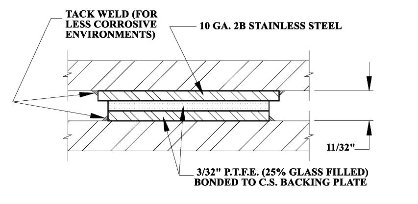
One combination of materials that we recommend is that of PTFE, 25% glass filled, bonded to stainless steel. Both materials resist oxidation and have long lives even in stressful environments. For large slide plates, galvanized steel can be used in place of stainless to reduce the cost.
Assembly Basics
Slide plates are usually arranged in what is known as a ‘sandwich’ formation, which consists of an upper slide plate component and a lower slide plate component.
The lower slide plate may also be welded to a stationary support (i.e. structural steel member), which grounds the plate, while the other plate is attached to the moving component directly. As the system moves, friction is transferred at the intersection of the two plates.
When ordering, always specify the dimensions of the upper and lower slide plate. As a rule, the upper slide plate should be large enough to completely cover the lower plate at all times.
Recommended Applications / Temperature Limits
-320F to +500F with low PSI
Different plates are suited for different temperature limits. While all plates have been rigorously tested for suitability within industrial settings, understanding the particular variables of that setting is vital to purchasing the appropriate plate for each application.
TEMPERATURE CONSIDERATIONS
PTFE, 25% glass filled, provides a low coefficient of friction for most combinations of temperature and load. Diagram B, on Page 193, shows the recommended conditions for 3/32” PTFE, 25% glass filled. For most applications, PTFE, 25% glass filled, is adequate when the temperature is less than 400 °F. When the slide bearing plate must function at higher temperatures, graphite can be used instead of PTFE, 25% glass filled. The load-bearing capacity of graphite is not sensitive to increases in temperature, but the adhesive used to bond the graphite to its metal backing is. It is good practice to use additional mechanical fasteners such as counter-sunk screws to help hold the graphite in place when the temperatures are above 500 °F. For combinations of temperature and load beyond the capabilities of graphite, special designs must be considered.
ATTACHMENT CONSIDERATIONS
Welding is the most common method of attaching the slide bearing plate to supporting metal structures. When this approach is used a slide plate must be designed with a “lip” since the welding’s extreme temperature may break the bond between the low-friction material and the metal plate. A 1/4” “lip” is adequate for most welded installations. When welding cannot be used (for safety or other reasons) to attach the slide plates, bolting is the most common substitute.
Before we begin constructing your slide bearing plates, we need to know the following:
• The material you desire for the low-friction surface, based on the highest combinations of temperature and load the component will experience.
• The desired size and shape for the low-friction surface.
• The type of metal, size, and shape you desire for the backing steel. Most designers choose galvanized or stainless steel.
Slide bearing plates are components of many products Piping Technology & Products, Inc. supplies such as guided pipe shoes and upthrust constants. As a result, we have extensive experience in bonding PTFE, 25% glass filled, and graphite to metal plates. Modern adhesives are adequate for most applications. However, mechanical fasteners such as countersunk screws can be added when needed. If you have unique applications, we will be happy to custom design a practical solution for your application.
NON-STANDARD ASSEMBLY CONFIGURATIONS
Slide Plates for Higher Load Capacities Notes:
1. Pressure range: 75 PSI to 2,200 PSI
2. Temperature range: -320 °F to 400 °F
3. Alternate backing materials are available.
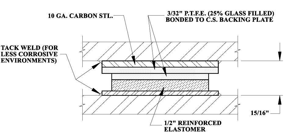
Slide Plates for Deflection & Expansion at Higher Loads
Notes:
1. Pressure range: 75 PSI to 1,500 PSI
2. Temperature range: -50 °F to 200 °F
3. Alternate thicknesses of reinforced elastomer available.
Slide Plates For Welding To Mating Surfaces
Notes:
1. Pressure range: 75 PSI to 2,000 PSI
2. Temperature range: -320 °F to 400 °F
3. Alternate backing materials are available.
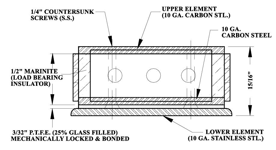
Slide Plates For High Temperature & High Load Bearing
Notes:
1. Pressure range: 100 PSI to 2,500 PSI
2. Temperature range 1/2” insulator: 400 °F to 800 °F
3. Coefficient of friction:
0.08 @ min. pressure
0.06 @ max. pressure
Support Assembly Components
Piping Technology & Products, Inc. maintains an extensive inventory of components required for pipe hanger and
support assemblies. Most of these are industry standards that have been used by piping designers for many
years. One of the value-added services we provide is assembly and tagging of units before shipping so field crews
can install them with minimal effort. Since we work with these materials daily, it is easier for us to do assemblies and
verify components and dimensions than it is for a field crew, for whom installing pipe supports is only one of many
tasks to be performed on a given workday.
Many assemblies are attached to the pipe with clamps. Our inventories include all types of clamps made from
carbon steel with galvanized and black finishes. We can fabricate clamps from alloy steels for high-temperature
applications in which standard clamps are not adequate. When ordering clamps, please add an “A” to the figure
number of any items to be fabricated from alloy material. We have included a chart to help with the specification of
special clamps for high-temperatures and heavy loads.
To compensate for pipe movement, a designer may choose from a variety of clevis hangers, roller hangers, and
adjustable bands to support the pipe. These are linked to the supporting structure with rods and other hardware
components. Beam attachments and other accessories are attached to the supporting structure to complete the
assembly. All of these components must be strong enough to support the loads in the environment where they are
installed. Galvanized components are often used to resist corrosion.
Saddle coverings are used with insulated pipes in order to provide protection to the insulation at points of support.
Roller stands, elbow supports, and other items can be supplied in adjustable models which allow field crews to make
easy installations.
Hold-downs are special clamping supports used on pipes that are subject to vibrations and stresses, such as those
near compressors. The hold-downs dampen these forces by transferring them to the supporting structure and thus
protect the piping system.
Pipe Saddles & 30″ Galvanized Riser Clamp
Nominal Insulation Table (Size vs. Actual)
NOMINAL INSULATION THICKNESS (in.)
INSULATION O.D. (in.)
APPROX. INSULATION THICKNESS (in.)
Pipe size: 1/2" (O.840 O.D.)
1
2 7/8
1
1 1/2
4
1 9/16
2
5
2 1/16
2 1/2
6 5/8
2 7/8
3
7 5/8
3 3/8
3 1/2
8 5/8
3 7/8
4
9 5/8
4 3/8
Pipe size: 3/4" (1.050 O.D.)
1
2 7/8
7/8
1 1/2
4
1 7/16
2
5
1 15/16
2 1/2
6 5/8
2 3/4
3
7 5/8
3 1/4
3 1/2
8 5/8
3 3/4
4
9 5/8
4 1/4
Pipe size: 1" (1.315 O.D.)
1
3 1/2
1 1/16
1 1/2
4 1/2
1 9/16
2
5 9/16
2 1/8
2 1/2
6 5/8
2 5/8
3
7 5/8
3 1/8
3 1/2
8 5/8
3 5/8
4
9 5/8
4 1/8
Pipe size: 1 1/4" (1.66 O.D.)
1
3 1/2
15/16
1 1/2
5
1 11/16
2
5 9/16
1 15/16
2 1/2
6 5/8
2 1/2
3
7 5/8
3
3 1/2
8 5/8
3 1/2
4
9 5/8
4
Pipe size: 1 1/2" (1.90 O.D.)
1
4
1 1/16
1 1/2
5
1 9/16
2
6 5/8
2 3/8
2 1/2
7 5/8
2 7/8
3
8 5/8
3 3/8
3 1/2
9 5/8
3 7/8
4
10 3/4
4 7/16
Pipe size: 2" (2 3/8" O.D.)
1
4 1/2
1 1/16
1 1/2
5 9/16
1 9/16
2
6 5/8
2 1/8
2 1/2
7 5/8
2 5/8
3
8 5/8
3 1/8
3 1/2
9 5/8
3 5/8
4
10 3/4
4 3/16
Pipe size: 2 1/2" (2 7/8" O.D.)
1
5
1 1/16
1 1/2
6 5/8
1 7/8
2
7 5/8
2 3/8
2 1/2
8 5/8
2 7/8
3
9 5/8
3 3/8
3 1/2
10 3/4
3 15/16
4
11 3/4
4 7/16
Pipe size: 3" (3 1/2" O.D.)
1
5 9/16
1
1 1/2
6 5/8
1 9/16
2
7 5/8
2 1/16
2 1/2
8 5/8
2 9/16
3
9 5/8
3 1/16
3 1/2
10 3/4
3 5/8
4
11 3/4
4 1/8
Pipe size: 3 1/2" (4" O.D.)
1
6 5/8
1 5/16
1 1/2
7 5/8
1 13/16
2
8 5/8
2 5/16
2 1/2
9 5/8
2 13/16
3
10 3/4
3 3/8
3 1/2
11 3/4
3 7/8
4
12 3/4
4 3/8
Pipe size: 4" (4 1/2" O.D.)
1
6 5/8
1 1/16
1 1/2
7 5/8
1 9/16
2
8 5/8
2 1/16
2 1/2
9 5/8
2 9/16
3
10 3/4
3 1/8
3 1/2
11 3/4
3 5/8
4
12 3/4
4 1/8
Pipe size: 4 1/2" (5" O.D.)
1
7 5/8
1 5/16
1 1/2
8 5/8
1 13/16
2
9 5/8
2 5/16
2 1/2
10 3/4
2 7/8
3
11 3/4
3 3/8
3 1/2
12 3/4
3 7/8
4
14
4 1/2
Pipe size: 5" (5 9/16" O.D.)
1
7 5/8
1
1 1/2
8 5/8
1 1/2
2
9 5/8
2
2 1/2
10 3/4
2 9/16
3
11 3/4
3 1/16
3 1/2
12 3/4
3 9/16
4
14
4 3/16
Pipe size: 6" (6 5/8" O.D.)
1
8 5/8
15/16
1 1/2
9 5/8
1 7/16
2
10 3/4
2
2 1/2
11 3/4
2 1/2
3
12 3/4
3
3 1/2
14
3 5/8
4
15
4 1/8
Pipe size: 7" (7 5/8" O.D.)
1
9 5/8
1
1 1/2
10 3/4
1 1/2
2
11 3/4
2
2 1/2
12 3/4
2 1/2
3
14
3 1/8
3 1/2
15
3 5/8
4
16
4 1/8
Pipe size: 8" (8 5/8" O.D.)
1
10 3/4
1 1/16
1 1/2
11 3/4
1 1/2
2
12 3/4
2
2 1/2
14
2 5/8
3
15
3 1/8
3 1/2
16
3 5/8
4
17
4 1/8
Pipe size: 9" (9 5/8" O.D.)
1
11 3/4
1 1/16
1 1/2
12 3/4
1 1/2
2
14
2
2 1/2
15
2 5/8
3
16
3 1/8
3 1/2
17
3 5/8
4
18
4 1/8
Pipe size: 10" (10 3/4" O.D.)
1
12 3/4
1
1 1/2
14
1 9/16
2
15
2 1/16
2 1/2
16
2 9/16
3
17
3 1/16
3 1/2
18
3 9/16
4
19
4 1/16
Pipe size: 11" (11 3/4" O.D.)
1
14
1 1/8
1 1/2
15
1 9/16
2
16
2 1/16
2 1/2
17
2 9/16
3
18
3 1/16
3 1/2
19
3 9/16
4
20
4 1/16
Pipe size: 12" (12 3/4" O.D.)
1
15
1 1/8
1 1/2
16
1 9/16
2
17
2 1/16
2 1/2
18
2 9/16
3
19
3 1/16
3 1/2
20
3 9/16
4
21
4 1/16
Pipe size: 14" (14" O.D.)
1
16
2
1 1/2
17
1 7/16
2
18
1 15/16
2 1/2
19
2 7/16
3
20
2 15/16
3 1/2
21
3 7/16
4
22
3 15/16
Large sizes, insulation O.D. are in 1" increments.
Insulation thicknesses through 36" same as nominal.
All dimensions rounded to the nearest 1/16".
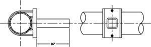
Instrument Supports – Welded and Adjustable Components
PT&P offers a complete line of adjustable instrument support components which, when combined, will create various configurations to your exact requirements or individual needs. We also provide welded instrument supports fabricated according to your specifications.
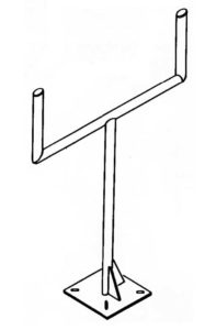
Welded Instrument Support / Stand
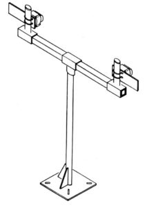
Adjustable Instrument Support / Stand
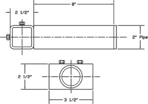
ADJUSTABLE INSTRUMENT SUPPORTS COMPONENTS
Primary support components are available in various mount styles, including floor mounts, wall mounts, u-bolt mounts, and cable mounts. These primary mounts can be used independently or together with secondary components to construct various packages for individual needs.
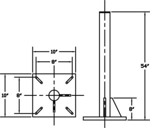
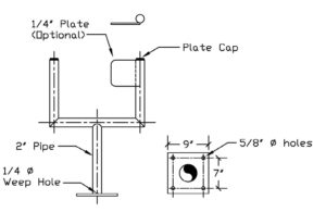
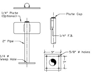
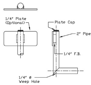
PTP-IS-600 Primary component has a 2” pipe extension 54” long, designed for grade mounting of instrument assemblies, comes with slotted hole in base.
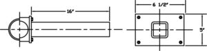
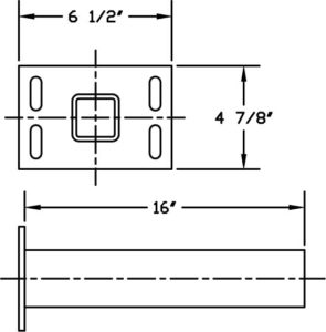
PTP-IS-610 Primary component has a 2” square extension 16” long, designed for mounting on vertical or horizontal lines.
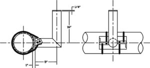
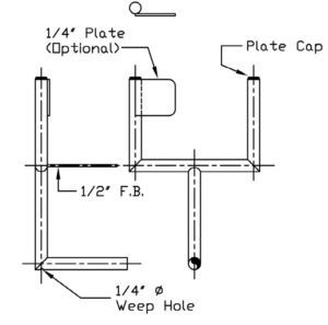
PTP-IS-620 Primary component has a 2” pipe, at a right angle with a vertical leg, designed for mounting on vertical lines.
PTP-IS-630 Primary component has a 2” pipe, at a right angle with a vertical leg, designed for mounting on horizontal lines.
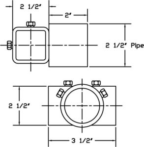
PTP-IS-640 Female adaptor with two 2” extension 2” long, provides female connection to 2” pipe components, used for constructing multiple instrument support systems.
PTP-IS-650 Adaptor with 2” pipe extension 8” long.
PTP-IS-660 2” square extension component, 16” long, with 2” u-bolt mount, for constructing various instrument support configurations.
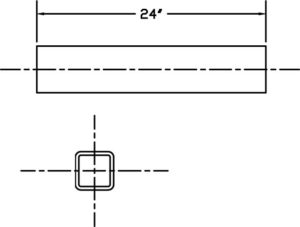
PTP-IS-670 2” square component, 24” long designed for use in constructing multiple support mounts and other applicable configurations as required.
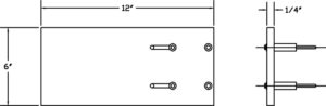
PTP-IS-680 Secondary component, with 2” u-bolt mount, provides auxiliary equipment mount and/or flag for identification.
PTP-IS-690 Primary component, 2” square extension 16” long, designed for mounting on walls and columns.
Note: The extension lengths shown on primary components are standard, other lengths can be furnished on request.
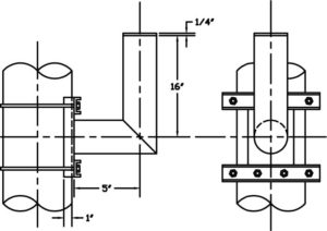
WELDED INSTRUMENT SUPPORTS
Welded instrument supports may be fabricated in any desired configuration according to the customer’s individual requirements and design specifications.
Examples of various welded instrument support configurations:
Welded Instrument Support Configuration (Diagram A)
Welded Instrument Support Configuration (Diagram B)
Welded Instrument Support Configuration (Diagram 2A)
Welded Instrument Support Configuration (Diagram 2B)
Attached to instrument; welded or clamped on stand.
Function:
Support and hold instrument at fixed location.
Hold instrument during plant operation.
Support instrumentation during operations.
Support instrumentation during operations.
Used in combination with primary supports to support instrumentation.
Location:
Where instrument is welded to structure
Bolted into concrete or welded to structure.
Bolted to walls and other vertical surfaces.
Bolted on the floor or in the ground.
Attached to primary instrument stands, usually floor or wall mounts.
Marinite® Technical Information
Marinite can be used as the insulating material in hot piping supports. The most widely known grade for Marinite is grade P. Marinite-P is most often used as structural insulation because of its high dimensional stability. Marinite-P is incombustible, provides high insulation values, and high compressive strengths and is thus appropriate in high-load and high-temperature applications. The material minimizes decay, rust, and corrosion and it resists damage during installation and provides durable service. The material acts as a suitable insulator in fireproofing and heat processing equipment applications up to 1200°F (649°C).
Major Advantages:
• High Compressive Strength.
Deflects less than 1/10 in. per inch of thickness under 4000 psi
Deflects less than 3/64 in. per inch of thickness under 2000 psi
• High Tensile strength.
• High resistance to shear and traverse forces.
Major Applications:
• Hot Line Pipe Supports in Power Generation and Process Industries
• Structural Insulation in Pipe
• Supports Backup Insulation in Rotary Kilns of Lime and Cement Plants.
• Ceramics and Foundry applications.
Coefficient of Friction:
0.08 @ minimum pressure
0.06 @ maximum pressure
Firetemp® Technical Information
Firetemp®, usually known as Super Firetemp®, is widely used as insulation for hot piping supports. It is an inorganic incombustible material. Chemically, it features a xonotlite crystal structure that results in exceptional strength and extremely low water if hydration. Super Firetemp® is composed primarily of lime, silica, and reinforcing fibers. The product is white, essentially dust-free, and contains no asbestos. It is a very good material for structural insulation inserts.
Firetemp® insulation’s major advantages and applications are given below. For more detail please see the Insulation Comparison Table.
Major Advantages:
• Exceptionally High Strength
• Low Conductivity
• Easy Application
• Zero clearance to combustibles
• Temperature Range to 1800°F
• Asbestos-Free
Major Applications:
• Hot Line Pipe Supports in Power Generation and Process Industries
• Indoor and Outdoor Piping and Equipment
• Block Insulation
• Fire rated enclosures around kitchen exhaust hood
• Fireproofing structural steel
• Fire rated walls
Foamglas® Technical Information
Foamglas® insulation is a lightweight, rigid insulation composed of millions of completely sealed glass cells. Each cell serves as an insulating agent. Foamglas® is widely used in the cryogenic and hotline pipe supports and is fabricated in various ranges of shapes, thicknesses, and sizes to meet the particular requirements of an application.
One unique advantage that Foamglas® has is its very low moisture absorption. Since Foamglas® insulation is full of closed glass cells, it resists moisture in both liquid and vapor form. This guarantees the long-term performance of the insulation. Foamglas® insulation’s resistance to moisture ensures that properly installed, it retains its original thermal efficiency.
The major advantages and applications of Foamglas® insulation are listed below. For details about the physical and mechanical properties of the Foamglas® material, please refer to the table.
Major Applications: •Cryogenic and Hot Line Pipe Supports
•Cryogenic Tanks and Vessels
•Chilled and Hot Water Service Lines
•Overfit and Revitalize the Old Insulation
•Composite Insulation Systems for Special Conditions
Density
Foam Glass(8 pcf)
Compressive Strength
400.00
Flexural Strength (flat wise with grain) (psi)
80.00
Tensile Strength (with grain)(psi)
N/A
Modules of Elasticity (psi)
1.3 10^6
Closed Cell Content (%)
N/A
Temperature (F)-Continuous Operation
500 max.
K-Factor
N/A
Thermal Conductivity (btu/hr m^2 of)
0.7000
Shear (flat wise) (1/8″ thk.) (psi)
N/A
Density (lb/in^3)
0.0046
Water Absorption (%)
0.070
Calcium Silicate Technical Information
Calcium Silicate often serves as the insulation for pipe supports in high-temperature applications. Calcium Silicate is also known as Thermo-12/Blue. It is an insulating material composed of hydrous calcium silicate which, because of its lightweight, low thermal conductivity and exceptional structural strength are ideal for the insulation of high-temperature piping and equipment. Sometimes it is also used as block insulation. The pipe insulation comes in a complete selection of sizes. Block styles are available for application to various flat and curved surface areas.
Some of Calcium Silicate’s major advantages and applications are given below:
Major Advantages: • Temperature Range to 1200°F • Exceptional Strength • Low Thermal Conductivity • Easy Application: available sizes and shapes reduce the number of required joints and make Calcium Silicate easy to work with. • Energy Savings: low thermal conductivity provides significant energy savings. • Adaptable: Calcium Silicate can also be used on various shapes and sizes of surfaces. • Fire Resistant. • Low Chloride Content: low corrosivity. • Asbestos-Free.
Major Applications: • Hot Line Pipe Supports in Power Generation and Process Industries. • Indoor and Outdoor Piping and Equipment. • Block Insulation – insulation of various flat and curved surface areas.
Polyurethane Foam (PUF) Technical Information
Polyurethane foam is one of the major components of pre-insulated pipe supports manufactured at Piping Technology & Products. Polyurethane is different from most plastic materials in that it can be tailored to meet various load requirements of varying applications. Polyurethane foams are produced by reacting an equal ratio of di- or polyisocyanurates with polyols, in the presence of water, which acts as the blowing agent. Polyisocyanurates are formed when a higher ratio of di- or polyisocyanate are mixed with the polyol. All rigid foams made from polyisocyanurate systems have some form of polyurethane in them and can be called polyurethane foam. The physical properties differ very little at high densities. Polyisocyanurate foams are used in applications where dimensional stability over 200 deg F is required. However, for cryogenic applications, where your pipeline insulation is not exposed to high temperatures, PUF is an acceptable substitution.
A common method used to obtain a change in load capacity is a change in density. At Piping Technology and Products, we offer 10 lbs. / ft3, 14 lbs. / ft3, and 20 lbs. / ft3 densities.
Density varies when the amount of blowing agent (water content) changes. The density of polyurethane decreases with increase in water content (See Fig. 1). This relationship can be shown as follows:
W = 3.706 / D1.126
Where: W = % of water content
D = Density of foam (lbs./ft3.)
In addition to density, the strength of a rigid urethane foam is also influenced by many factors such as catalyst, surfactant, type of mixing, the type of foaming system: base polyol and isocyanate, and the influence of each of these on the foam cell structure.
Rigid urethane foams generally have an elastic region in which stress is nearly proportional to strain. They do not exactly follow Hooke’s Law (stress is proportional to strain) because the curve is very slightly “S” shaped. Fig. 2 shows this in detail.
Polyurethane is anisotropic, or polyurethane is stronger in the direction of foam rise. At Piping Technology and Products, the anisotropic character or directional properties of our polyurethane is reduced by overloading the mold used to form the polyurethane. By overloading the mold, we can control the cell structure and provide uniform physical properties. A relationship between compressive strength and the density of the foam is given in Fig. 3.
Polyurethane is a thermosetting material; however, it does soften slightly with increased temperature and hardens somewhat at very low temperatures. Softening at high temperatures affects the polyurethane in two ways: (a) loss of strength properties and (b) change in foam dimensions (particularly low-density foams). Low temperatures generally have a very little effect on polyurethane properties other than to make them a little harder and more brittle. See Fig. 4 for these effects.
Rigid polyurethane foams have a relatively large amount of cross-linking as the foam expands. Our suppliers of the raw chemicals control the degree of cross-linking by functionality (higher functionality produces more cross-links) and molecular weight of the components in the blend. The rigid cells provide the poured foam with strength and the interior space provides low thermal conductivity. Water is used as the blowing agent for foam in this 10 to 40 lb. density range.
The relationship between temperature, thermal conductivity and the density of polyurethane foam is shown in Fig. 5.
The relationships of foam’s density with its Elastic Modules in Compression, Tensile Strength, Elastic Modules in Tension, and Shear Strength are given in Figs. 6 through 9 respectively. Please see the following for the respective curves.
Piping Technology & Products has a complete manufacturing facility for production of polyurethane required for pipe supports. We invite our customers to visit our facility and observe the fabrication of insulated pipe supports of all types.
We use cookies on our website to give you the most relevant experience by remembering your preferences and repeat visits. By clicking “Accept”, you consent to the use of ALL the cookies.
This website uses cookies to improve your experience while you navigate through the website. Out of these, the cookies that are categorized as necessary are stored on your browser as they are essential for the working of basic functionalities of the website. We also use third-party cookies that help us analyze and understand how you use this website. These cookies will be stored in your browser only with your consent. You also have the option to opt-out of these cookies. But opting out of some of these cookies may affect your browsing experience.
Necessary cookies are absolutely essential for the website to function properly. These cookies ensure basic functionalities and security features of the website, anonymously.
Cookie
Duration
Description
cookielawinfo-checkbox-analytics
11 months
This cookie is set by GDPR Cookie Consent plugin. The cookie is used to store the user consent for the cookies in the category "Analytics".
cookielawinfo-checkbox-functional
11 months
The cookie is set by GDPR cookie consent to record the user consent for the cookies in the category "Functional".
cookielawinfo-checkbox-necessary
11 months
This cookie is set by GDPR Cookie Consent plugin. The cookies is used to store the user consent for the cookies in the category "Necessary".
cookielawinfo-checkbox-others
11 months
This cookie is set by GDPR Cookie Consent plugin. The cookie is used to store the user consent for the cookies in the category "Other.
cookielawinfo-checkbox-performance
11 months
This cookie is set by GDPR Cookie Consent plugin. The cookie is used to store the user consent for the cookies in the category "Performance".
viewed_cookie_policy
11 months
The cookie is set by the GDPR Cookie Consent plugin and is used to store whether or not user has consented to the use of cookies. It does not store any personal data.
Functional cookies help to perform certain functionalities like sharing the content of the website on social media platforms, collect feedbacks, and other third-party features.
Performance cookies are used to understand and analyze the key performance indexes of the website which helps in delivering a better user experience for the visitors.
Analytical cookies are used to understand how visitors interact with the website. These cookies help provide information on metrics the number of visitors, bounce rate, traffic source, etc.
Advertisement cookies are used to provide visitors with relevant ads and marketing campaigns. These cookies track visitors across websites and collect information to provide customized ads.
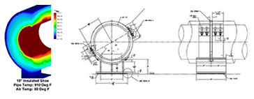
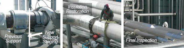
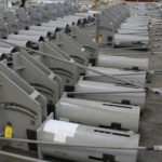
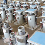
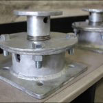
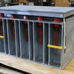
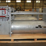
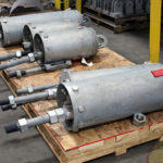

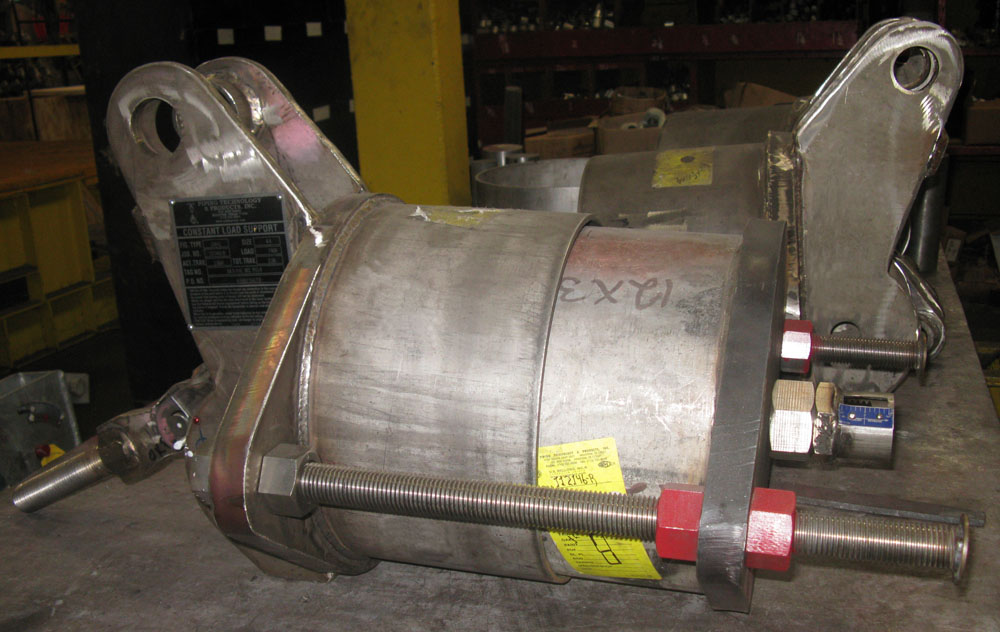
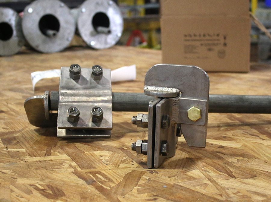
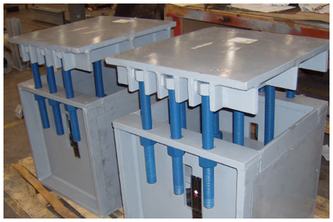
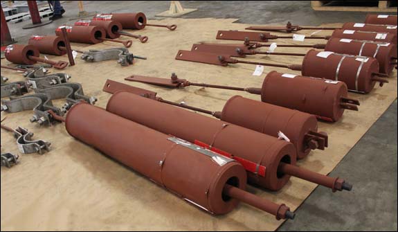
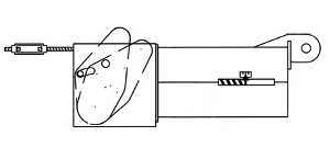
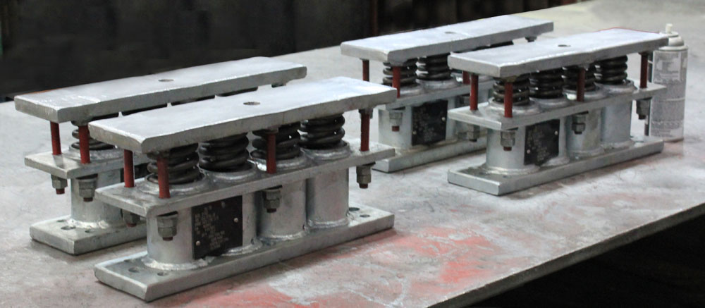
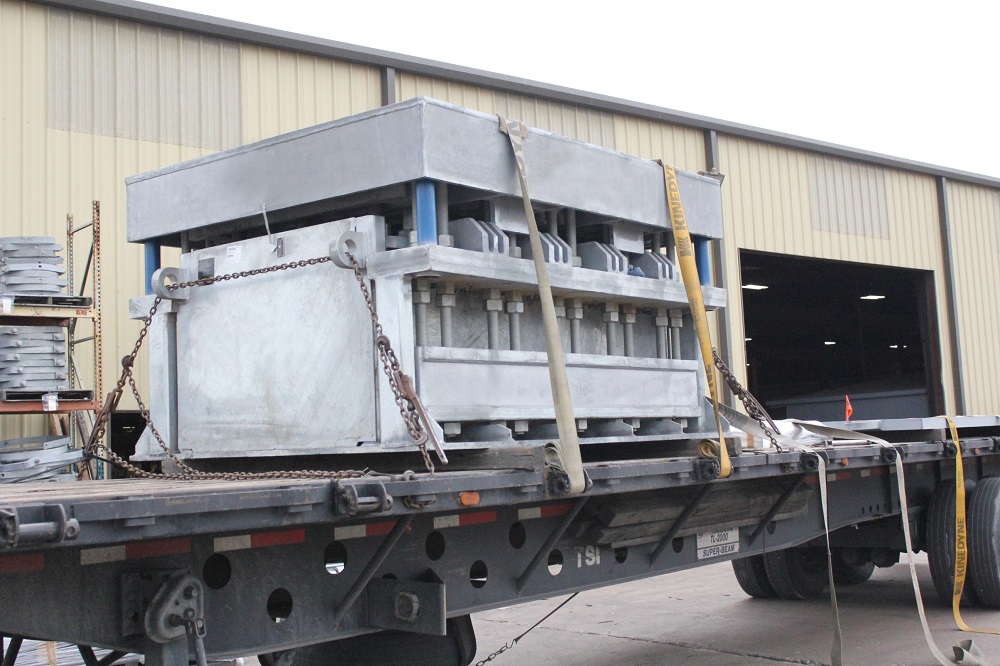
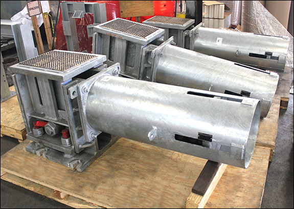
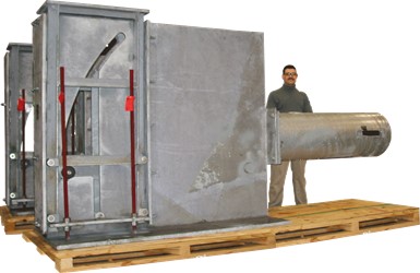
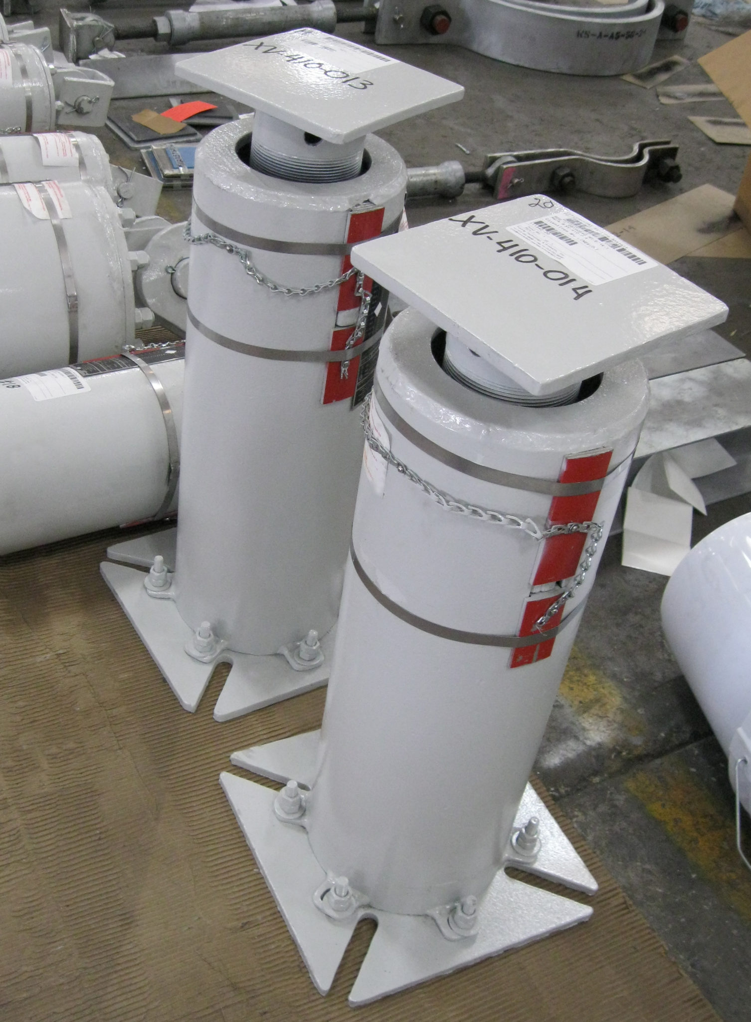
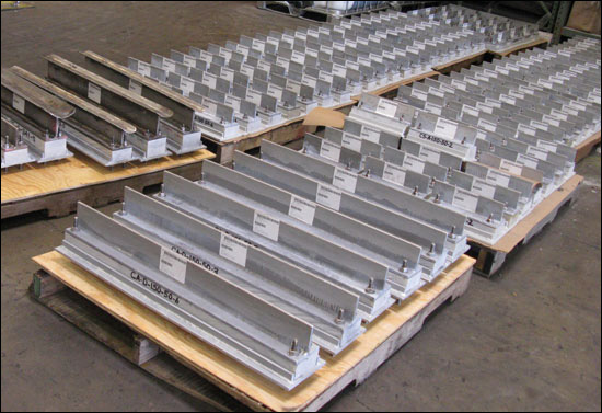
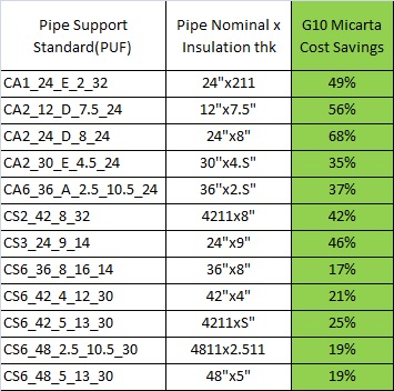
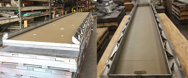
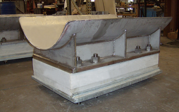
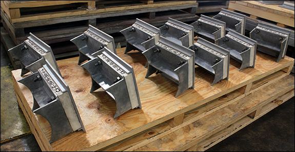
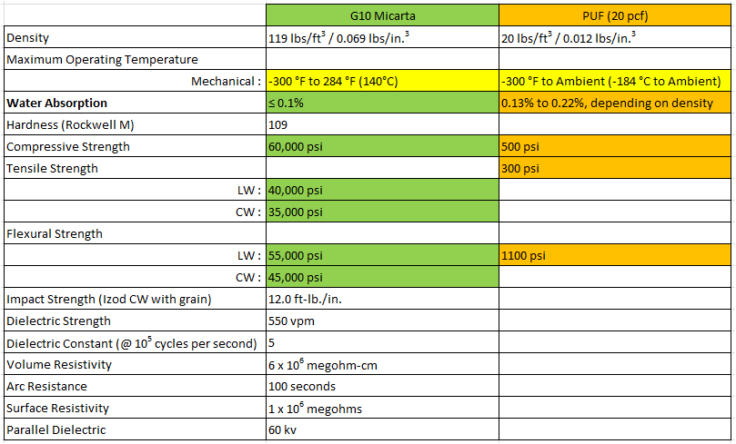
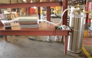
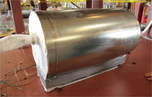
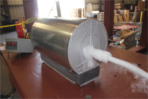
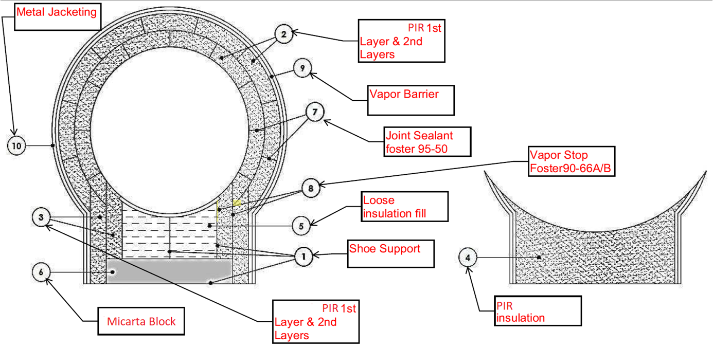
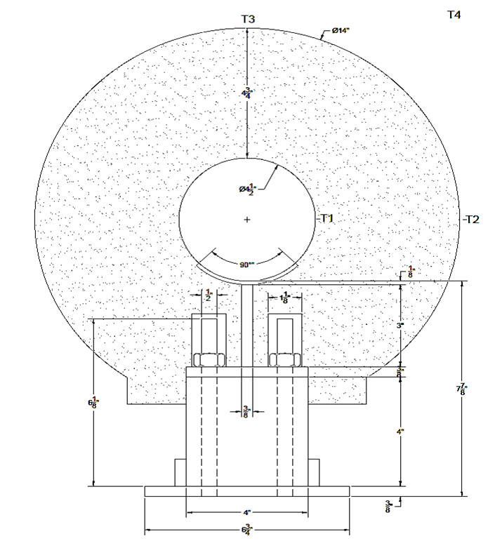
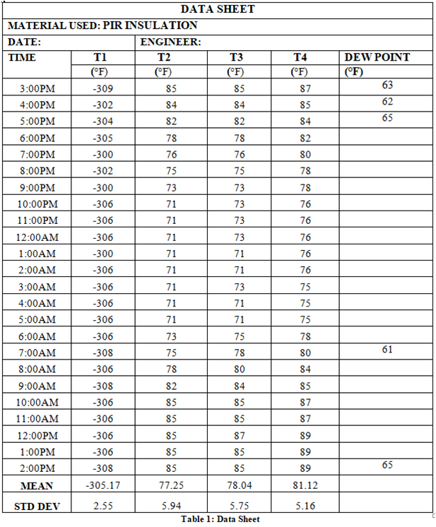
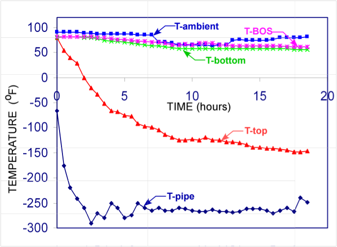
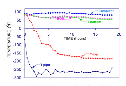


")
")
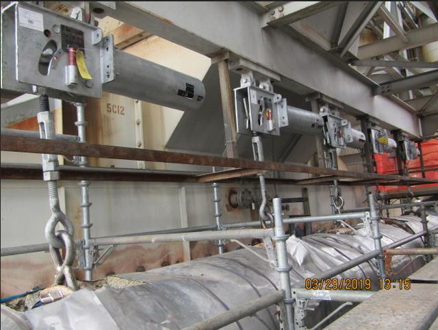


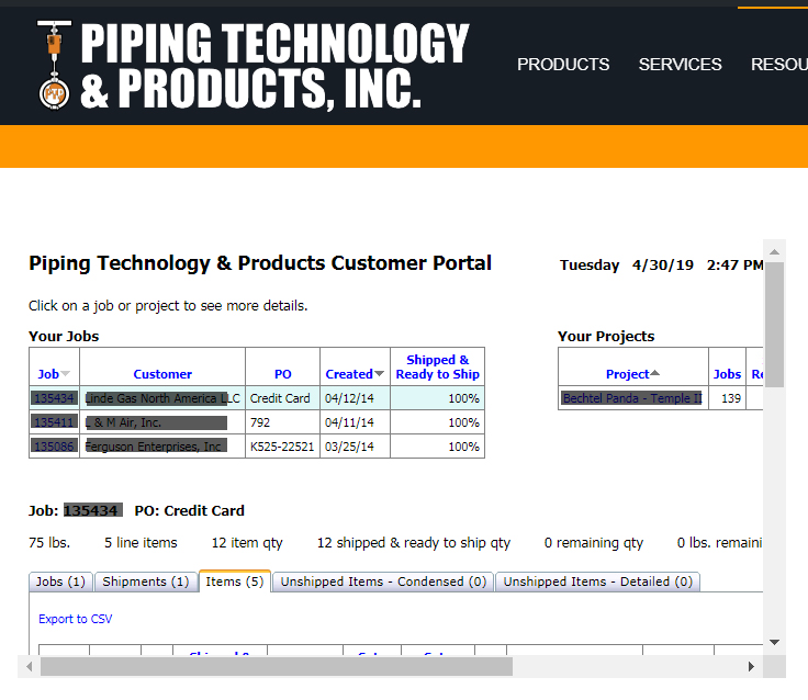
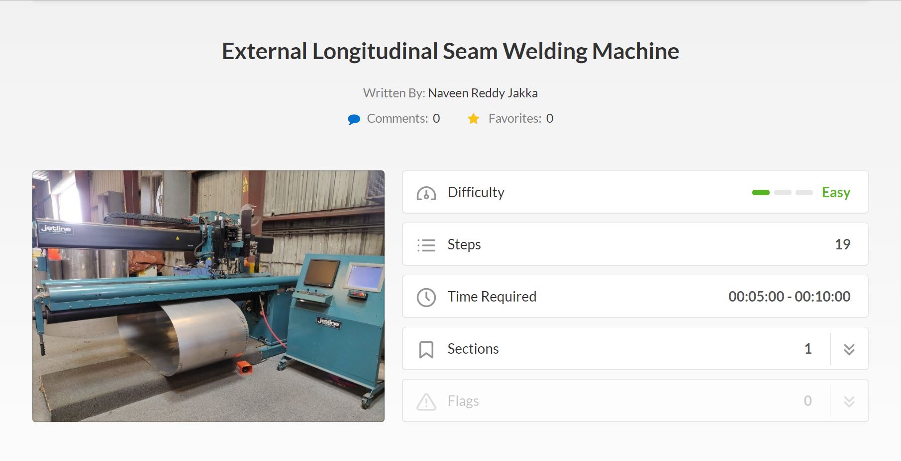
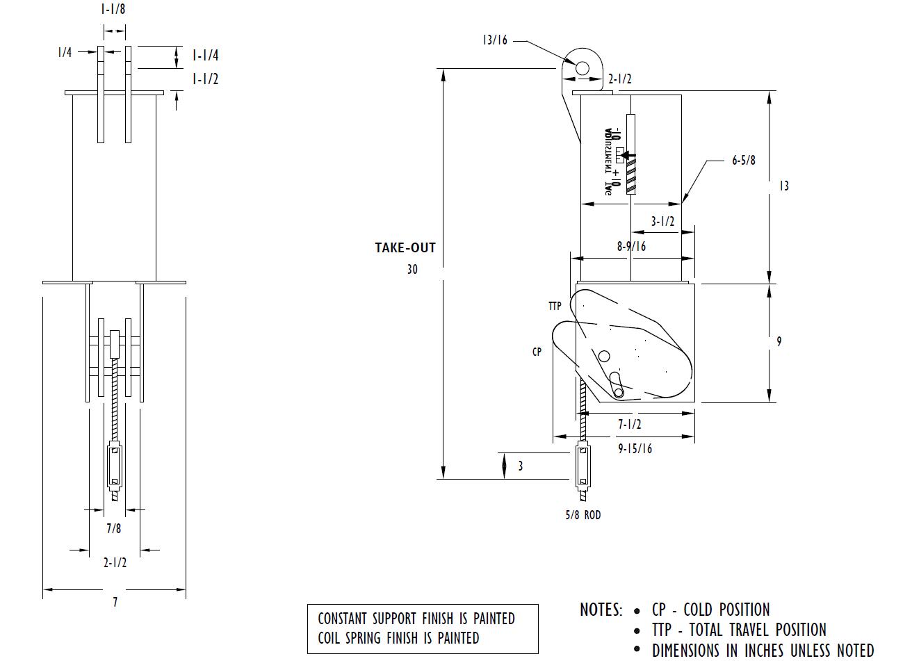
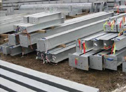
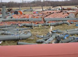
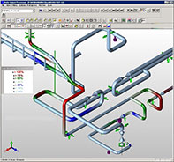
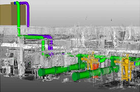
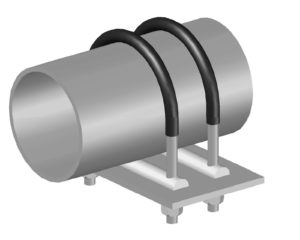
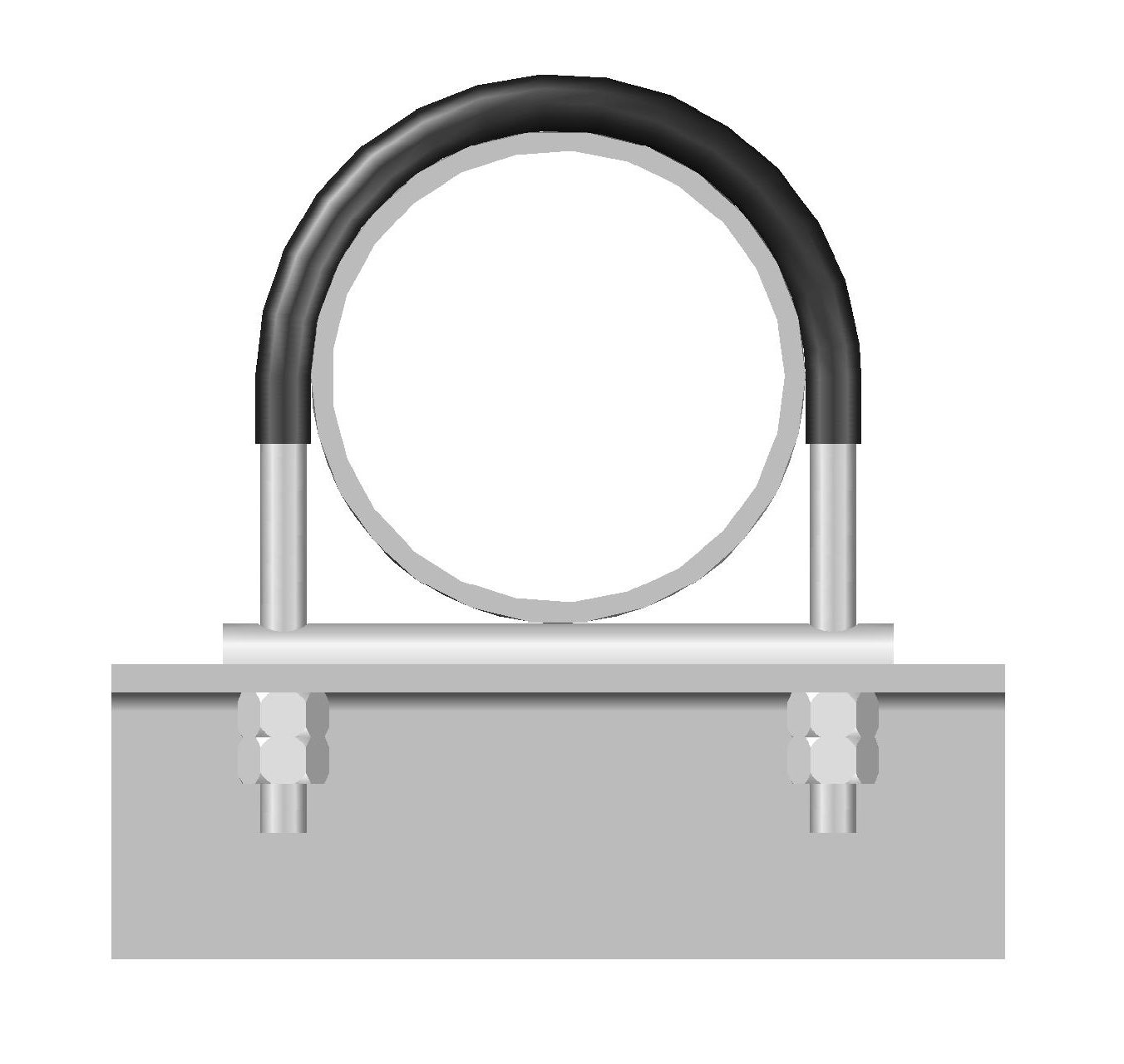
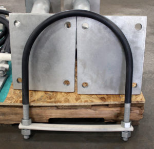
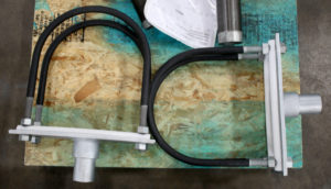
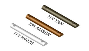
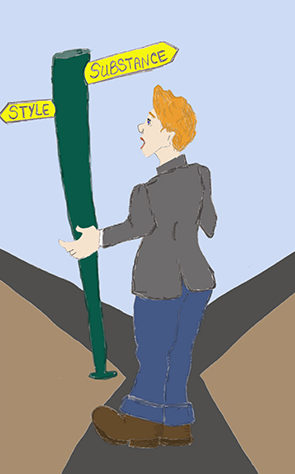


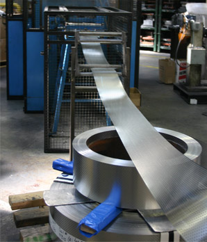
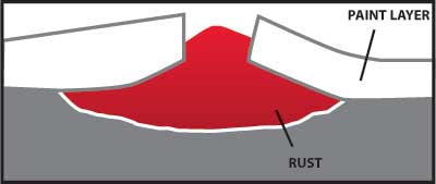
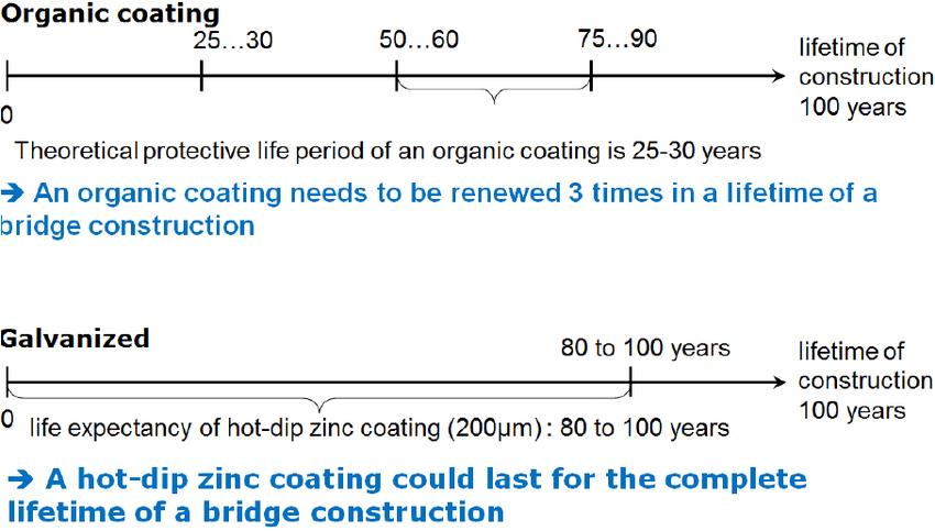
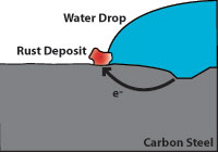
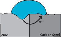
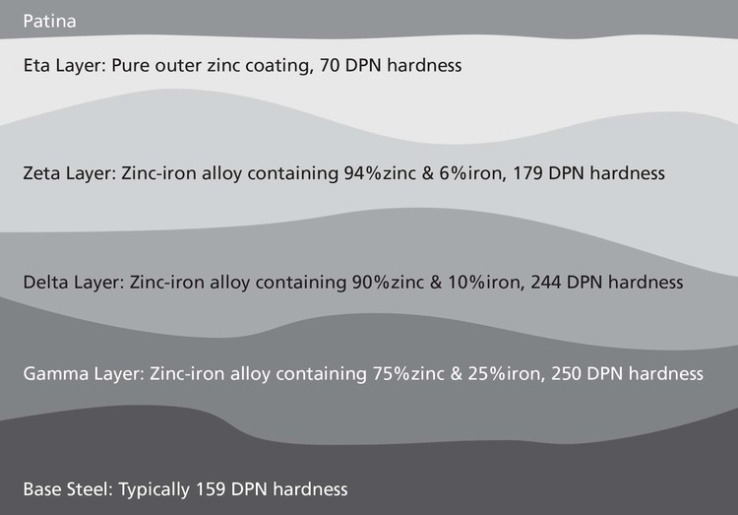
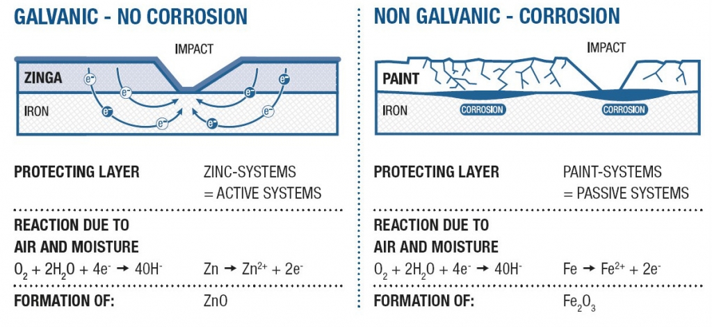
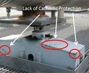
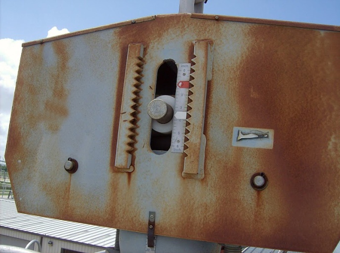
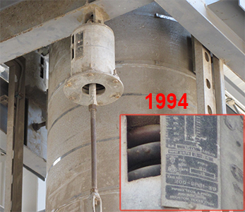
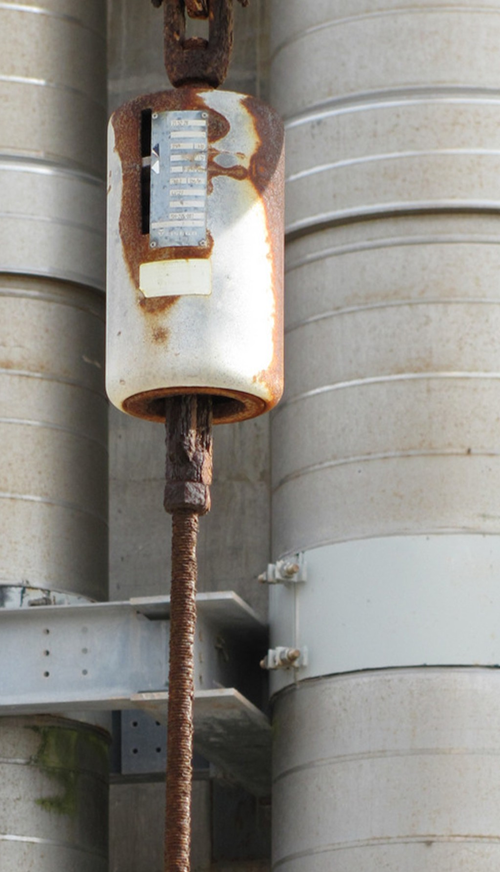
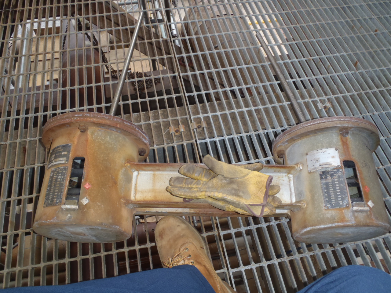
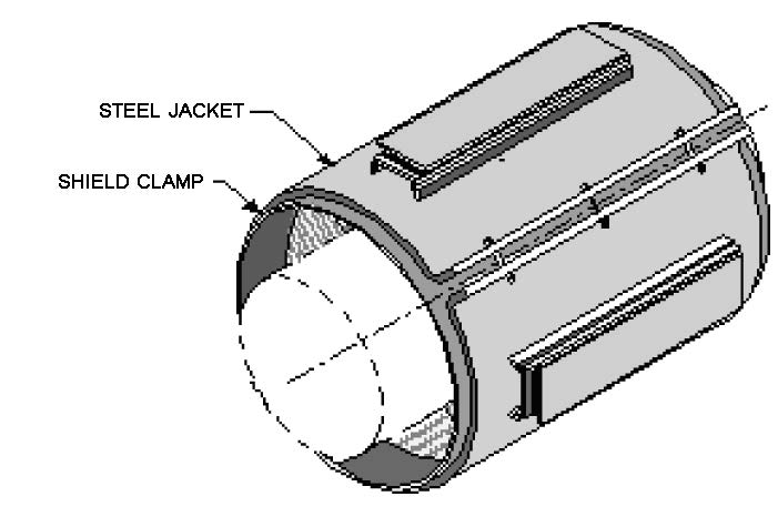
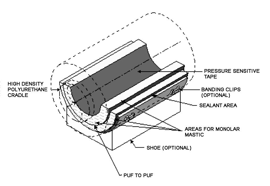
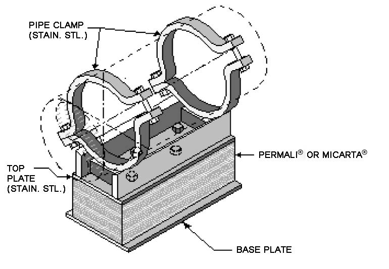
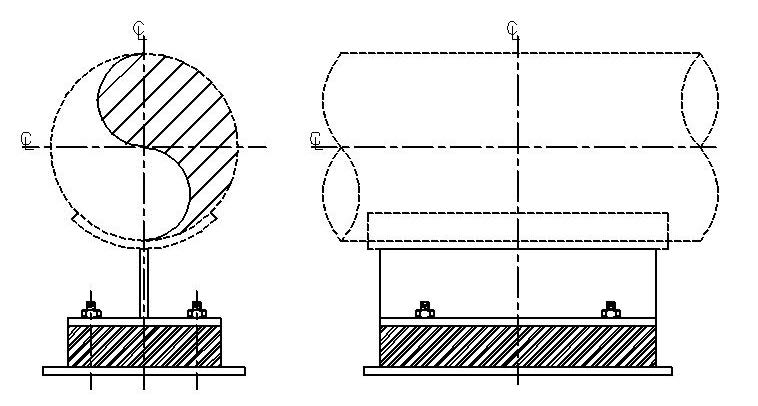
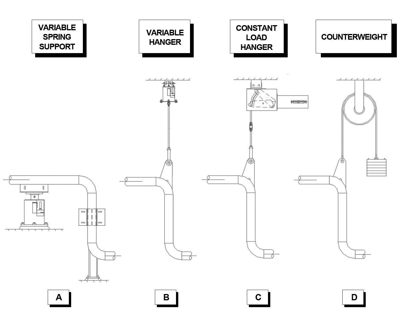
 Diagram A: Sandwich Concept