Big Ton Spring Supports Designed for Propane Dehydrogenation Facility
June 27, 2016
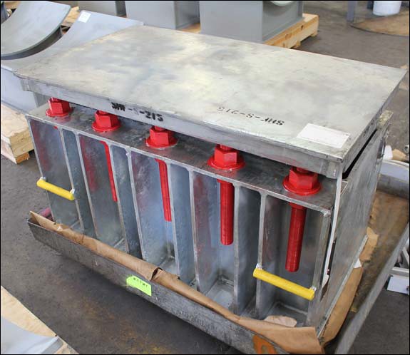
PT&P custom designed big ton spring supports for a propane dehydrogenation facility in Texas. The components within these assemblies include the spring housing, load columns, travel stops, spring coils and lifting lugs. While both assemblies measure 42” x 24” x 26-1/2”, they were each modified based on independent specifications for operating loads and movement. The first will accommodate a load of 94,261 lb. and 0.085” of movement, while the second will accommodate a load of 102,219 lb. with 0.08” of movement.
This type of support is ideal for applications, such as pressure vessels, that combine very heavy loads with thermal expansion because of the stability they provide. The big tons were tested in the load cell to insure proper operation throughout the entire working range of the coils.
June 2001 News: Issue 1
June 4, 2001
PT&P Verifies New Designs for LNG Phenolic Base Support with Load Testing
Load Testing
Piping Technology & Products, Inc. performs thorough product testing to verify new designs to a LNG Laminated Phenolic base support for an E&C company located in Houston, Texas. In order to determine the failure loads for a 30″ diameter, pre-insulated shoes and a 6″ diameter Laminated Phenolic base support respectively, PT&P performed lateral-load and axial load tests. The load tests performed ensure the pre-insulated pipe shoes can safely sustain the specified design load. The insulated shoes tested for the E&C company will be in service in 2001 at Atlantic LNG, where they will be used to support the liquid nitrogen gas (LNG) lines.
Big Ton Springs Installation Guide 1. Measure the existing installed load setting height to make sure that the big ton spring will fit tightly into the space provided. Shim from below as needed to ensure proper fit.
2. Place the big ton spring in the designated location, making sure that all required slide plates, shims, or auxiliary steel are in their proper positions.
3. Travel stop bolts can be released after all testing has been done. The travel stops are painted red and located on each end of the big ton spring. Follow the steps below to release the travel bolt stops. Please refer to the drawings to the left.
(a) Turn the nut on travel stop bolt No. 1 one-half turn; repeat on bolts 2 through 4.
(b) Repeat in this sequential order until the load is released. The load has now been transferred to whatever the big ton spring is supporting.
4. CAUTION: Be sure that the nuts on the travel stop bolts are backed off enough to accommodate the appropriate travel (Example: 1 inch of travel – the nuts should be backed off by 2 inches from the bottom of the travel stop plate.)
5. At this time the Lifting Eye Bolts may be removed.
Tension Systems
In some cases, a straight line system of axial bellows anchors and guides is not practical or desired; or there is no reasonable way/ place to anchor the bellows thrust loads. In such cases self restrained bellows assemblies may be used, such as the double hinge restrained bellows shown below. Thermal expansion (or contraction) in the long pipe is absorbed by an offset deflection of the double hinge assembly. Bellows thrust load is carried by hinge bars, gimbals, tie rods or other such devices; hence normal tension is maintained in the pipe system and main anchors and full lateral restraint guides are unnecessary.
We use cookies on our website to give you the most relevant experience by remembering your preferences and repeat visits. By clicking “Accept”, you consent to the use of ALL the cookies.
This website uses cookies to improve your experience while you navigate through the website. Out of these, the cookies that are categorized as necessary are stored on your browser as they are essential for the working of basic functionalities of the website. We also use third-party cookies that help us analyze and understand how you use this website. These cookies will be stored in your browser only with your consent. You also have the option to opt-out of these cookies. But opting out of some of these cookies may affect your browsing experience.
Necessary cookies are absolutely essential for the website to function properly. These cookies ensure basic functionalities and security features of the website, anonymously.
Cookie
Duration
Description
cookielawinfo-checkbox-analytics
11 months
This cookie is set by GDPR Cookie Consent plugin. The cookie is used to store the user consent for the cookies in the category "Analytics".
cookielawinfo-checkbox-functional
11 months
The cookie is set by GDPR cookie consent to record the user consent for the cookies in the category "Functional".
cookielawinfo-checkbox-necessary
11 months
This cookie is set by GDPR Cookie Consent plugin. The cookies is used to store the user consent for the cookies in the category "Necessary".
cookielawinfo-checkbox-others
11 months
This cookie is set by GDPR Cookie Consent plugin. The cookie is used to store the user consent for the cookies in the category "Other.
cookielawinfo-checkbox-performance
11 months
This cookie is set by GDPR Cookie Consent plugin. The cookie is used to store the user consent for the cookies in the category "Performance".
viewed_cookie_policy
11 months
The cookie is set by the GDPR Cookie Consent plugin and is used to store whether or not user has consented to the use of cookies. It does not store any personal data.
Functional cookies help to perform certain functionalities like sharing the content of the website on social media platforms, collect feedbacks, and other third-party features.
Performance cookies are used to understand and analyze the key performance indexes of the website which helps in delivering a better user experience for the visitors.
Analytical cookies are used to understand how visitors interact with the website. These cookies help provide information on metrics the number of visitors, bounce rate, traffic source, etc.
Advertisement cookies are used to provide visitors with relevant ads and marketing campaigns. These cookies track visitors across websites and collect information to provide customized ads.