Hydraulic Snubbers for an Ammonia Plant in Louisiana

February 20, 2024

Hydraulic Snubbers For An Ammonia Plant In Louisiana

Type: Hydraulic Snubbers
Design: 3,000-15,400 lb load/5″-12″ stroke
Material: Carbon Steel
Size: 31″ up to 148″ pin-to-pin and cylinder diameters from 2.5″ to 5″

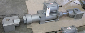
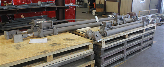
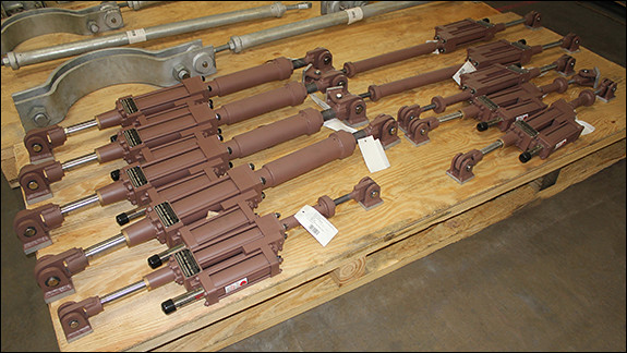
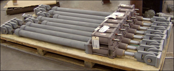
Piping Technology & Products designed these hydraulic snubbers for an ammonia plant in Louisiana. The snubbers ranged in length from 31" up to 148" pin-to-pin and cylinder diameters from 2.5" to 5". They are designed for an operating load ranging from 3,000 lb. to 15,400 lb. and have a 5" to 12" stroke. Hydraulic snubbers are designed to protect the piping system when a sudden, heavy load is applied (such as an earthquake of high intensity), which can cause serious vibrations leading to damage and possible failure of the piping system.

Most hydraulic snubbers have a piston which is relatively unconstrained in motion at low displacement rates. At high displacement rates the piston "locks up", that is, the force required to move the piston increases substantially, usually as a result of the closing of a valve.

Hydraulic snubbers are used in many applications and are typically needed urgently in operational facilities. We have provided these products in all major verticals including refining, petrochemical, renewables, and power operations.. Our hydraulic snubbers are built in accordance with ASME Boiler and pressure vessel code and our Laconia, New Hampshire operations have ASME Nuclear Stamp "NS" for nuclear applications.

PT&P REF. ORIGINAL POST 11232016

Hydraulic Snubber Assemblies Designed for a Geothermal Power Plant

May 16, 2023

Hydraulic Snubber Assemblies Designed For A Geothermal Power Plant

Fronek Anchor/Darling, a division of PT&P, designed and manufactured hydraulic snubbers for Geothermal power plants. Historically, these plants are located near tectonic plate boundaries in the Earth’s crust, where thermal activity is easily tapped. This heat energy is transferred into electrical energy through the use of turbines, generators, and heat exchangers. These snubbers are fabricated from stainless steel and include a special paint system suitable for a Hydrogen Sulfide (H2S) environment. All of the snubbers for this application were a 2-1/2 bore size, capable of operating at loads up to 10,000 lb., and were provided with either 6″ or 12″ of available stroke. The Pin-to-Pin dimensions ranged from approximately 36″ to 54″. Each snubber was tested at its rated capacity to ensure acceptable dynamic performance once it was installed in the field.

A hydraulic snubber is used to protect piping from unexpected events, such as water hammers or seismic activity prevalent in geothermal applications, while allowing the piping to move freely during normal operation conditions – a typical movement driven by thermal growth. We have seen hydraulic snubbers used in a large number of different applications, typically during the design phase of a project when the Piping Engineer is designing for a line that may have transient events but must also accommodate thermal growth. A hydraulic snubber works by passing hydraulic fluid between 2 chambers via a poppet valve. When the speed of the fluid passes a threshold, the poppet valve closes and causes the Hydraulic snubber to become rigid support. There is a small relief passage between the two chambers that will eventually allow the Hydraulic snubber to “reset.”

These snubbers were designed and manufactured for one of the world’s leading developers, operators, and manufacturers of geothermal renewable energy. We have long-standing relationships with our clients as a result of our long history and extensive portfolio of products and services. In this case, we supported this client’s initiatives for over 20 years worldwide with their projects in Nevada, California, Oregon, Israel, Hawaii, and Guatemala. In addition to hydraulic snubbers, we provided constant assemblies, pipe shoes, guides, anchors, pipe hanger hardware, slide-bearing plates, and variable spring supports.

PT&P REF. ORIGINAL POST 03232021

Hydraulic Snubbers Designed for LLDPE Chemical Plant

June 17, 2016

Hydraulic Snubbers Designed For Lldpe Chemical Plant

These Fig. 511 AD long hydraulic snubbers were created for a linear low-density (LLDPE) chemical plant in Louisiana. The snubbers with two (2) rear brackets range in length from 34-⅝” to 49”. They are designed with spherical, self-aligning ball bushings that allow for + 5° of angular motion or misalignment.  The snubbers can handle maximum loads varying up to 5520 lb. Cylinder sizes are 1-½” and 2-½” and have a 6” stroke. The hydraulic fluid is petroleum based and the seals are a mix of buna-nitrile and polyurethane and the pressurized hydraulic reservoir allows mounting in any spatial orientation. The snubbers are painted with a primer that utilizes zinc filled powder manufactured by Tnemec. Ⓡ  The formulation for the primer is Series H90-97 | Tneme-Zinc.

Hydraulic Snubbers Designed for an LNG Facility in Texas

September 6, 2014

Hydraulic Snubbers Designed For An Lng Facility In Texas

Fronek Anchor/Darling Enterprises, a division of PT&P, designed snubbers for a LNG facility in Texas. These Fig. 511 AD hydraulic snubbers range in size from 76″ – 85″ piston-to-piston and are fabricated from carbon steel. They are designed for a maximum load of 32,000 lb., 6″ stroke and have a 4″ diameter cylinder. Hydraulic snubbers are designed to protect the piping system when a sudden, heavy load is applied (such as an earthquake of high intensity), which can cause serious vibrations leading to damage and possible failure of the piping system. A cycle test throughout the full stroke from zero to fully extended was performed prior to shipment

7 Ways to Extend the Lifespan of a Hydraulic Snubber

March 9, 2012

Follow these 7 steps below to maintain and extend the life span of your hydraulic snubber.

Hydraulic Snubber Assemblies For A Lng Processing Facility In Peru
Hydraulic Snubber Assembly

1. Observe the fluid level to make sure there is sufficient fluid for the snubber to operate
2. Check for leaks – If the fluid level is decreasing, determine the cause and effect remedial action.
3. Check the condition of the load pins and spherical ball bushings. Apply a high pressure grease for long-term benefits.
4. Check the condition of the exposed portion of the piston rod. Check for scoring, paint or other physical damage.
5. Check the condition of the piston rod wiper. Verify that it’s in position and working effectively.
6. Check for evidence of abuse like welding arc strikes, bent or dented parts, scratched paint, etc.
7. Finally, check the overall physical appearance. This encompasses all of the above.


Four Steps to Inspecting Your Hydraulic Snubber

January 27, 2012

Do you have a hydraulic snubber would you like inspect, but don’t know where to begin? Visit our visual media section and learn How To Inspect a Hydraulic Snubber.

This video will go over the four main steps when inspecting a hydraulic snubber. If you have any questions, feel free to call us at 713-731-0030 or email us at info@pipingtech.com.

Hydraulic Snubber vs. Mechanical Snubber

March 11, 2011

Have you ever wondered which type of  snubber to select for your piping system? Should you pick a hydraulic snubber or should you pick a mechanical snubber? Which one is right for your application? This seems to be a common concern for quite a few of our customers, so we have just recently published an article that discusses the pros and cons for both hydraulic and mechanical snubbers.  Check out the article, Suitability of Snubbers for Various Applications.

Hydraulic Snubber Assemblies For A Lng Processing Facility In Peru
Hydraulic Snubber Assemblies for a LNG Processing Facility in Peru

Do you require snubbers for a current or upcoming project? Get pricing today!

Request-A-Quote

Hydraulic Snubbers (Fig. 511 AD) with Protective Boots Designed for a Hydro-sulfuric Acid Environment in a Geothermal Power Plant

February 14, 2011

Hydraulic Snubbers (Fig. 511 Ad) With Protective Boots Designed For A Hydro-Sulfuric Acid Environment In A Geothermal Power Plant   Hydraulic Snubbers (Fig. 511 Ad) With Protective Boots Designed For A Hydro-Sulfuric Acid Environment In A Geothermal Power Plant

Fronek Anchor/Darling, a division of PT&P, designed and manufactured hydraulic snubbers with protective boots for a hydro-sulfuric acid environment in a geothermal power plant. They measure 53-5/8″ pin-to-pin with a 3-1/4″ cylinder bore size and 6″ stroke.

The snubbers are designed for an actual load of 15,400 lb., but have a rated load capacity of 20,000 lb. They are fabricated from carbon and alloy steel, and include two coats of epoxy-based paint. An activation velocity test was performed, along with a release rate and drag characteristics test.

Need further assistance selecting your snubber?
> contact our team of engineers
> submit a request for quote
> view more information on Snubbers

What is a hydraulic snubber?

November 3, 2010

A hydraulic snubber is a device that permits pipe deflection under normal operating conditions, but when subjected to an impulse load, such as an earthquake, water hammer, etc., the snubber becomes activated and acts as a rigid restraint torestrict pipe movement as a result of the unwanted impulse loading.

A hydraulic snubber includes a hydraulic fluid reservoir and cylinder to produce the restraint force when activated.

Hydraulic Snubbers With Protective Boots
Hydraulic Snubbers with Protective Boots

What are the ranges of motion of a hydraulic snubber?

Hydraulic snubbers are designed with a pre-defined amount of stroke. Those stroke ratings are available in 6 inch increments from 6″ to 24″. The amount of movement, which could be accommodated by any stroke designation, would depend upon the initial setting. For example, setting a 6″ stroke snubber at the midpoint would mean that during operation, the snubber could extend 3″ maximum or retract 3″ maximum.

Hydraulic Snubbers (Fig. 511 Ad) With Protective Boots Designed For A Hydro-Sulfuric Acid Environment In A Geothermal Power Plant
Hydraulic Snubbers with Protective Boots

How can I test a snubber?

Field testing of snubbers is not recommended. In order to accurately confirm the function of a snubber, a certified test machine must be utilized to accurately simulate impulse loading.

Hydraulic Snubber Being Tested On The Stadas Test Machine
Hydraulic Snubber Being Tested on the STADAS Test Machine

How do I use a snubber?

The main criteria to remember when utilizing snubbers is that they are intended to be passive elements during normal operation and will become activated only when that unwanted impulse event is present. When that impulse event dissipates, the snubber will become deactivated and thus produce negligible restraint to pipe deflections under standard operating conditions.

Mechanical Snubber Installed In The Field
Mechanical Snubber Installed in the Field

When should I install a piping snubber?

Because snubbers are not meant to be active support components, they could be installedat any time during the construction phase. It should also be noted that pipingsnubbers can be retrofit to existing systems at any time.

Close Up View Of Hydraulic Snubber Installed In The Field
Close Up View of Hydraulic Snubber Installed in the Field

What does a pipe snubber look like?

This is what a pipe snubber looks like:
Hydraulic Snubber

What is a pipe snubber?

A pipesnubber is a device that permits pipe deflection under normal operatingconditions, but when subjected to an impulse load, such as an earthquake, waterhammer, etc., the snubber becomes activated and acts as a rigid restraint torestrict pipe movement as a result of the unwanted impulse loading.

Mechanical Snubber Assemblies Custom Designed For An Oil Refinery In California
Custom Designed Mechanical Snubber Assemblies


What is a shock suppressor?

A shocksuppressor is another name for a snubber, which is a device that permits pipedeflection under normal operating conditions, but when subjected to an impulseload, such as an earthquake, water hammer, etc., the snubber becomes activatedand acts as a rigid restraint to restrict pipe movement as a result of theunwanted impulse loading.

Mechanical Snubber Assemblies Custom Designed For An Oil Refinery In California
Mechanical Snubber Assemblies

Hydraulic Snubber Assemblies for a LNG Processing Facility in Peru

November 1, 2010

Hydraulic Snubber Assemblies For A Lng Processing Facility In Peru

These hydraulic snubber assemblies were designed with maximum load capacities ranging from 1700 lb. to 59,400 lb. All of the snubbers were provided with an overall stroke of 6” and were preset to the midpoint of the total stroke, meaning that during operation, these snubbers could accommodate piping deflections of  +/- 3” from the installed position.

Hydraulic Snubber Assemblies For A Lng Processing Facility In Peru

The piston diameters range from 1-1/2″ to 6″ and the total assembly length ranges from 31-1/2″ to 220″. The largest assembly required a custom extension section to eliminate the risk of buckling under compression loads. Two-thirds of the assemblies included dual end brackets and the remaining assemblies included an end bracket/clamp combination. The housing, extension piece and end brackets are fabricated from carbon steel, while the cylinders, pins and two of the end brackets are fabricated from polished stainless steel. Standard “lock and bleed-down” tests were performed prior to shipping to a LNG processing facility in Peru.

Do you require a shock control device in your piping system? Price a snubber today!

Request-A-Quote

Hydraulic Snubber and 3-Bolt Clamp Assemblies for a Refinery Expansion Project

November 3, 2009
Hydraulic Snubber And 3-Bolt Clamp Assemblies
Hydraulic Snubber and 3-Bolt Clamp Assemblies (Item #2 & #3)
Hydraulic Snubber And 3-Bolt Clamp Assemblies For A Refinery Expansion Project
Hydraulic Snubber (Item #1)

Fronek Anchor/Darling Enterprises, Inc. and PT&P designed and fabricated hydraulic snubber and 3-bolt clamp assemblies for a refinery expansion project in Louisiana. A cycle test throughout the full stroke from zero to fully extended was performed prior to shipping.

Item #1: C-C: 61″, stroke: 12″, cylinder size: 5″ dia., max. load: 50,000 lb., 3-bolt clamp: A240 Gr. 304 SS, pipe size: 12″

Item #2: C-C: 71-7/8″, stoke: 6″, cylinder size: 4″ dia., max. load: 30,000 lb., -bolt clamp: A-36 carbon steel, pipe size: 16″

Item #3: C-C: 85-5/8″, stoke: 6″, cylinder size: 4″ dia., max. load: 30,000 lb., -bolt clamp: A-36 carbon steel, pipe size: 16″

Do you see a need for snubbers or clamps in your piping system? Get pricing today!
Request-A-Quote

140,700 lb. Load Hydraulic Snubbers

March 5, 2008
140,700 Lb. Load Hydraulic Snubbers
140,700 lb. Load Hydraulic Snubbers
140,700 Lb. Load Hydraulic Snubbers
Side View of Snubber

Anchor/Darling Enterprises, Inc., a wholly owned subsidiary of Piping Technology & Products, Inc. designed and fabricated these hydraulic snubbers for a power plant in Turkey. They are adjustable type snubbers with two rear brackets. The hydraulic snubbers can absorb loads up to 140,700 lb.

Design:

Temperature: 375°F
Pressure: 1,750 PSIG
Stroke: 6″

Do you see a need for snubbers in your piping system? Get pricing today!
Request-A-Quote

Snubbers with Yoke Clamps for a LNG Plant

May 31, 2006
Snubbers With Yoke Clamps For A Lng Plant
Snubbers with Yoke Clamps for a LNG Plant

Snubbers With Yoke Clamps For A Lng Plant
Snubbers

Snubbers are restraining devices. They allow free thermal movement during normal operations but restrain in abnormal circumstances such as with an earthquake. These snubbers were fabricated from carbon steel. They measure 2 1/2” x 24” and the yoke clamps have pipe sizes of 23” and 25”. Each snubber weighs 890 lb. and has a travel capacity of 24”. Designed for the support of a cryogenic line, these snubbers can handle loads of up to 2,900 lb.

Want to learn more about snubbers? Instantly view a past snubbers webinar today!


Access-Our-Webinar-Archives


Top