Hydraulic Snubber Assemblies Designed for a Geothermal Power Plant

May 16, 2023

Hydraulic Snubber Assemblies Designed For A Geothermal Power Plant

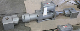
Fronek Anchor/Darling, a division of PT&P, designed and manufactured hydraulic snubbers for Geothermal power plants. Historically, these plants are located near tectonic plate boundaries in the Earth’s crust, where thermal activity is easily tapped. This heat energy is transferred into electrical energy through the use of turbines, generators, and heat exchangers. These snubbers are fabricated from stainless steel and include a special paint system suitable for a Hydrogen Sulfide (H2S) environment. All of the snubbers for this application were a 2-1/2 bore size, capable of operating at loads up to 10,000 lb., and were provided with either 6″ or 12″ of available stroke. The Pin-to-Pin dimensions ranged from approximately 36″ to 54″. Each snubber was tested at its rated capacity to ensure acceptable dynamic performance once it was installed in the field.

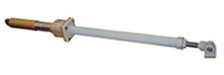
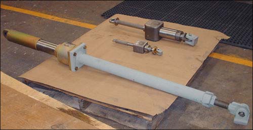
A hydraulic snubber is used to protect piping from unexpected events, such as water hammers or seismic activity prevalent in geothermal applications, while allowing the piping to move freely during normal operation conditions – a typical movement driven by thermal growth. We have seen hydraulic snubbers used in a large number of different applications, typically during the design phase of a project when the Piping Engineer is designing for a line that may have transient events but must also accommodate thermal growth. A hydraulic snubber works by passing hydraulic fluid between 2 chambers via a poppet valve. When the speed of the fluid passes a threshold, the poppet valve closes and causes the Hydraulic snubber to become rigid support. There is a small relief passage between the two chambers that will eventually allow the Hydraulic snubber to “reset.”

These snubbers were designed and manufactured for one of the world’s leading developers, operators, and manufacturers of geothermal renewable energy. We have long-standing relationships with our clients as a result of our long history and extensive portfolio of products and services. In this case, we supported this client’s initiatives for over 20 years worldwide with their projects in Nevada, California, Oregon, Israel, Hawaii, and Guatemala. In addition to hydraulic snubbers, we provided constant assemblies, pipe shoes, guides, anchors, pipe hanger hardware, slide-bearing plates, and variable spring supports.

PT&P REF. ORIGINAL POST 03232021

Pipe Support Field Service: Problem Resolution

November 27, 2017

** Turn up your speakers to hear the audio. Please be patient as the screen will become visible
shortly after the speaker begins the presentation. You may click the monitor icon below each
video to view the webinar in full-screen mode.

NOTE: PDH credits are NOT offered for our recorded webinars.

View the Slides for Above Webinar Here

​How to Inspect a Hydraulic Snubber

Follow these four steps when inspecting a hydraulic snubber:

  1. Inspect welded attachments
  2. Inspect the piston
  3. Inspect the fluid level
  4. Inspect hydraulic vent

Image

Shock Control, Restraint, and Support Devices Webinar

October 9, 2017

** Turn up your speakers to hear the audio. Please be patient as the screen will become visible
shortly after the speaker begins the presentation. You may click the monitor icon below each
video to view the webinar in full-screen mode.

NOTE: PDH credits are NOT offered for our recorded webinars.

View the Slides for Above Webinar Here

Suitability of Snubbers for Various Applications

By Dr. Hyder Husain Ph.D.
March 9, 2011

Snubbers are used as restraining devices to control abnormal movement of pipes and equipment due to dynamic events such as earthquakes, turbine trips, safety/relief valve discharge, rapid valve closure, or rupture of pipes. The design of a snubber allows free thermal movement of a component during normal operating conditions, but restrains the component in abnormal conditions.

The snubber restraint forces, as described above, can be generated using either mechanical or hydraulic methods.


Hydraulic Snubbers

Hydraulic snubbers have a piston which is relatively unconstrained during relatively low velocities as would be seen in normal thermal expansion/contraction cycles or slow oscillation of pipes. At high displacement rates, the piston “locks up” and the snubber acts as a rigid restraint.

Hydraulic Snubber

Hydraulic Snubber with an Overall Stroke of 6″

Our commercial hydraulic snubbers have a nominal fluid viscosity of 100cStrokes @ 40°C. Typically, the motion of the snubber-fluid shuts off the valve when the piston velocity reaches 8”/min or more. As a result, the snubber acts as a rigid component and transfers the shock load to the rigid foundation, saving the upstream components.


Mechanical Snubbers

Mechanical Snubber
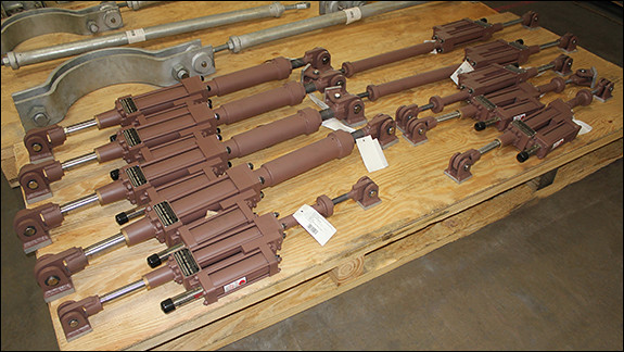
Similarly to hydraulic snubbers, mechanical snubbers use a telescoping cylinder to permit free movement of the pipe under normal operating conditions. When the threshold acceleration of 0.02 g’s is exceeded, an internal mechanism of the snubber activates, thereby locking the telescoping cylinder and subsequently producing our restraint force.


Hydraulic vs. Mechanical Snubbers

Because hydraulic snubbers have fewer internal components, they are preferred in outdoor applications or where a corrosive environment is present. Additionally, hydraulic snubbers can be easily designed to accommodate a wide range of pipe displacement.

Mechanical snubbers are optimum solutions for piping used in high radiation areas such as those seen in nuclear power plants because they do not utilize hydraulic fluid that may become degraded in radioactive environments.

Furthermore, mechanical snubbers require less maintenance overall and are considered “solid state” support components in the piping system. Hydraulic snubbers conversely require a routine inspection to detect leaking seals or loss of hydraulic fluid.


Dynamic Response

In regards to dynamic response, mechanical snubbers react consistently regardless of their Hydraulic Snubber And Mechanical Snubber
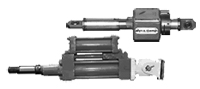
position during either compression or extension modes. However, hydraulic snubbers may show some variation in their dynamic response depending upon the piston location.  Therefore, when choosing a hydraulic snubber for a piping system, one must carefully determine the amount of stroke needed to adequately position the snubber piston orientation for optimum functionality.

Vibration in a Piping System

By Dr. Hyder Husain Ph.D.
January 6, 2011


Cause of Vibration 
All piping systems typically used in industrial application are made of elastic material. Elastic materials vibrate even under small perturbations due to their elastic properties. Since solid materials have a non-zero stiffness factor for both volumetric and shear deformations, these perturbations can generate waves with different velocities depending upon the deformation mode. Volumetric perturbations produce transverse waves while shear perturbations produce longitudinal waves.

External Perturbation  In an ideal situation, pipe vibration would be non-existent if the fluid could flow through the piping system without any disturbances that would cause perturbation. However, in real-life situations, there are many sources that generate perturbation in the piping system and subsequently cause vibration.

Causes of Perturbation Here we can separate the main causes into a few main categories:
(a) Mechanical, (b) Fluid Induced, (c) Transients

(a)  Mechanical:
(i)   Perturbation originating from the pump or compressor.
(ii)  Mechanical perturbation propagating from other moving mechanical components.

(b)  Fluid Induced:
(i)  Flow turbulence (broad band spectra): Function of Reynolds number
(ii)  Multiphase flow: Propagation of slugs (quasi-periodic) and their implosion/explosion may cause serious vibration.
(iii)  Bends & elbows: These produce secondary flows causing further interaction and enhancing strong vertical flows of quasi-periodic nature.
(iv) Valves: Valves cause flow separation and/or direction change which leads to high intensity turbulence (Reynolds number dependent).

(c)  Transients:
(i) Sudden rupture of pipe
(ii) Sudden closure of valve
(iii) External forces on the pipe or piping components

Causes of Perturbation Thorough plant design should ensure that the Eigen-modes and Eigen-values of the overall system subjected to external perturbations should not match those of the piping system when subjected to those same external perturbations.  Low frequency, long waves will cause immediate problems; whereas high frequency, low amplitude vibrations will cause fatigue failures over time.   Therefore, one must be careful in designing the piping system and should use various vibration mitigating devices placed at proper locations.  In addition, proper process controls should be used to reduce vibration especially in multiphase flows.

Snubbers: A General Overview

By Dr. Hyder Husain Ph.D.
December 2, 2010

Introduction: PT&P produces various kinds of snubbers. Why snubbers are used and how they function are briefly discussed here.

What are they?: Snubbers are restraining devices used to control the movement of pipe and equipment during abnormal dynamic conditions such as earthquakes, traveling shock waves caused by turbine trips, safety/relief valve discharge, rapid valve closure or accidental rupture of piping.

Where are they used?: Snubbers are extensively used in various applications including chemical plants, power plants (both conventional & nuclear), refineries, and structures such as suspension bridges and tall rise buildings in earthquake-prone areas.

How do they function?: The design of a snubber allows free thermal movement of components during normal operating conditions. Abnormal conditions activate the snubber to become momentarily rigid (locked condition). While locked, the snubber transmits the transient force to the ground or to a permanent structure without causing any damage to the downstream components. As soon as the transient force ceases, the snubber resumes its normal operation.

Types of Snubbers: There are two types of snubbers: (i) hydraulic and (ii) mechanical snubbers with various types of designs. However, the function of any design is the same—to protect the downstream structure from abnormal shocks. Snubbers are designed for various load ratings depending upon the magnitude of seismic activities and the criticality of fluid induced shocks.

Hydraulic Snubbers: This type consists of either two concentric cylinders or two parallel cylinders and their respective moving pistons. Both the main cylinder and the compensating cylinders are filled with fluid.  The main and the compensating cylinders are connected to velocity limiting valves and a main piston which works in either a push or pull mode. Under normal operating conditions, the valves remain open and allow the piston to move freely under thermal expansion/contraction of the supported component. When the threshold velocity (typically 8 in. per minute) is reached, the valve activates by closing the flow through the valve (also known as valve locking) and the flow through the system stops momentarily. At this point, the main piston that takes the shock load stops moving and the load is transmitted to the ground or to a permanent structure, thus avoiding any damage to the structure downstream of the snubber.  As soon as the shock wave passes, the snubber resumes normal operation.

Hydraulic Snubber
Hydraulic Snubbers

Mechanical Snubber: Similar to hydraulic snubbers, this type of snubber is comprised of a moving cylinder/rod arrangement. Unlike hydraulic snubbers, however, mechanical snubbers use mechanical means to provide the restraint force.

Mechanical Snubbers
Mechanical Snubbers

MSA Mechanical Snubber: With this type of snubber, the linear movement of the rod connected to the piping component is converted to rotary motion. When the centrifugal acceleration exceeds a certain threshold acceleration (typically 0.02g), a centrifugal type clutch flares out and locks at the peripheral slot of the cylinder and restricts linear motion.

Anchor-Darling Mechanical Snubber: With this type of snubber, the linear motion of the central rod that is connected to the structural component is converted to oscillatory motion via a verge mechanism. This oscillatory motion is in turn converted to rotary motion via a set of gears. As the linear velocity increases, the inertia force generated in the oscillating verge and the train of rotating gears increases. The extent of this increase depends upon the amount of inertial mass and gear train’s angular velocities thereby limiting the velocity of the piping components within the safe limit.

Hydraulic Snubbers Designed for LLDPE Chemical Plant

June 17, 2016

Hydraulic Snubbers Designed For Lldpe Chemical Plant

These Fig. 511 AD long hydraulic snubbers were created for a linear low-density (LLDPE) chemical plant in Louisiana. The snubbers with two (2) rear brackets range in length from 34-⅝” to 49”. They are designed with spherical, self-aligning ball bushings that allow for + 5° of angular motion or misalignment.  The snubbers can handle maximum loads varying up to 5520 lb. Cylinder sizes are 1-½” and 2-½” and have a 6” stroke. The hydraulic fluid is petroleum based and the seals are a mix of buna-nitrile and polyurethane and the pressurized hydraulic reservoir allows mounting in any spatial orientation. The snubbers are painted with a primer that utilizes zinc filled powder manufactured by Tnemec. Ⓡ  The formulation for the primer is Series H90-97 | Tneme-Zinc.

Shock Control, Restraint & Support Devices Webinar

June 9, 2016

This webinar is over, view the recording in the webinar archives

140,000 Lb. Load Adjustable Hydraulic Snubbers
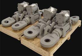
Explore the various applications of snubbers, sway braces and sway struts in piping systems and equipment. Learn how these products help prevent pipe system failure due to seismic loads, flow transients, wind loads, safety valve thrust loads or pipe rupture. Discover the various tests performed within PT&P’s facility to ensure product quality, including cycle testing, travel testing and load testing. Finally, view the value-added services offered by PT&P and rest assure that your shock control, restraint and support device needs can be covered by our 24×7 web-based emergency services, field services and quick-turn around time when you need it most.

The featured presenter, Jerry Godina has over 13 years experience as a pipe support designer and manages PT&P’s engineer training development program. He also inspects existing supports, consults on site remediation projects and oversees installation on a regular basis.

Hydraulic Snubber Designed for a Gas Turbine in a Natural Gas-Fired Combined Cycle Generating Power Plant

December 14, 2014

Hydraulic Snubber Designed For A Gas Turbine In A Natural Gas-Fired Combined Cycle Generating Power Plant

Fronek Anchor/Darling Enterprises Inc., a division of PT&P designed and fabricated this hydraulic snubber assembly for a gas turbine in a natural gas-fired combined cycle generating power plant in Pennsylvania. This fig -510AD is designed for a 10,000 lb. load and a 6″ stroke. It measures 28-1/2″ pin-to-pin and has a 2-1/2″ diameter cylinder. It is designed for an operating temperature of 1052°F and a movement of 4-1/8″. This snubber was tested using the STADAS test machine prior to shipping.

Hydraulic Snubbers Designed for a Geothermal Facility

March 19, 2012

Hydraulic Snubbers Designed For A Geothermal Facility

Fronek Anchor/Darling Enterprises, a division of PT&P designed and fabricated hydraulic snubbers for a geothermal facility in California. The Fig. 510 AD snubbers ranged in size from 34-3/4″ to 37-5/8″ piston-to-piston and were designed for a 50,000 lb. maximum load, 5″ cylinder size and a 6″ stroke. The Fig. 511 AD snubbers ranged in size from 56-15/16″ to 59-5/16″ P-P and were designed for a 20,000 lb. maximum load, 2-1/2″ cylinder size and a 6″ stroke. Hydraulic snubbers are designed to protect the piping system when a sudden, heavy load is applied (such as an earthquake of high intensity), which can cause serious vibrations leading to complete destruction. A custom three-bolt pipe clamp fabricated from carbon steel was designed to fit in a limited space. A cycle test throughout the full stroke from zero to fully extended was performed prior to shipment.

Snubbers: A General Overview

December 3, 2010

We recently posted a new Snubber article on our website.  It provides a technical look into both hydraulic and mechanical snubbers – how they are used in a piping system and how they function.  Most importantly, the article tells you the difference between various types of snubbers which is helpful in choosing the appropriate snubber for your piping system needs.

Snubbers: A General Overview

14 1/2&Quot; Diameter 225,000 Lb. Load Hydraulic Snubber
14 1/2" diameter 225,000 lb. load Hydraulic Snubber

Want to learn more about snubbers? Watch a recording of a past snubbers webinar now!
Access-Our-Webinar-Archives

Hydraulic Snubber Assemblies for a LNG Processing Facility in Peru

November 1, 2010

Hydraulic Snubber Assemblies For A Lng Processing Facility In Peru

These hydraulic snubber assemblies were designed with maximum load capacities ranging from 1700 lb. to 59,400 lb. All of the snubbers were provided with an overall stroke of 6” and were preset to the midpoint of the total stroke, meaning that during operation, these snubbers could accommodate piping deflections of  +/- 3” from the installed position.

Hydraulic Snubber Assemblies For A Lng Processing Facility In Peru

The piston diameters range from 1-1/2″ to 6″ and the total assembly length ranges from 31-1/2″ to 220″. The largest assembly required a custom extension section to eliminate the risk of buckling under compression loads. Two-thirds of the assemblies included dual end brackets and the remaining assemblies included an end bracket/clamp combination. The housing, extension piece and end brackets are fabricated from carbon steel, while the cylinders, pins and two of the end brackets are fabricated from polished stainless steel. Standard “lock and bleed-down” tests were performed prior to shipping to a LNG processing facility in Peru.

Do you require a shock control device in your piping system? Price a snubber today!

Request-A-Quote

Hydraulic Snubbers in Assembly

June 9, 2000
Hydraulic Snubbers In Assembly
Hydraulic Snubbers in Assembly

Shown above are hydraulic snubbers which are used to protect critical components in refineries, power plants and other industrial plants from sudden movement by the attached piping system. Engineers specify these for systems subject to sudden accelerations caused by earthquakes, extreme wind loads or water hammer. Hydraulic snubbers resist sudden rapid movement of the pipe by limiting the flow rate of the fluid inside the snubber. The device is designed to slow movement, such as would be expected during thermal expansion, has practically no resistance, but sudden rapid movement is resisted with a force proportional to the velocity raised to a power, where the power is determined by the orifice valve and flow pattern in the design. Selection of materials and liquids used will depend on the environment where the snubber is installed.

In need of new hydraulic snubbers? Get pricing today!

Request-A-Quote

Top