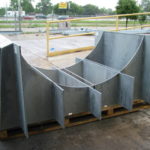
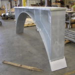
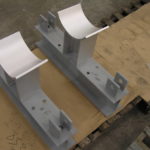
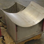
Pipe Saddles & Coverings

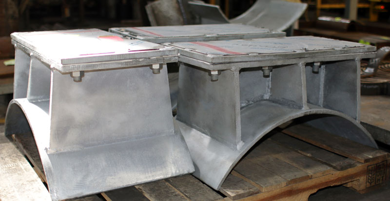
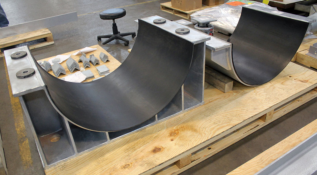
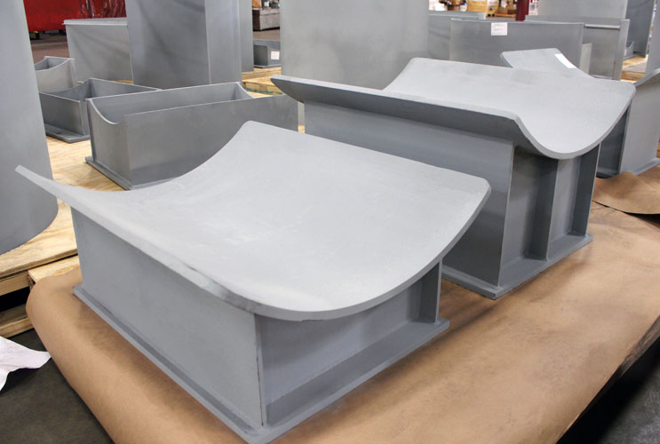
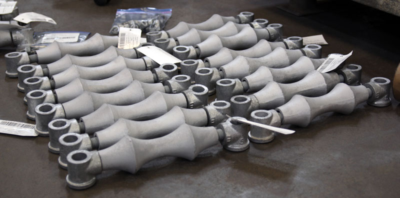
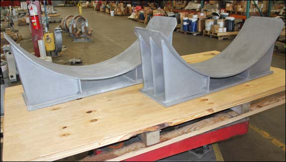
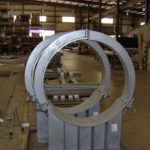
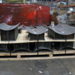
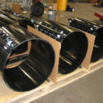
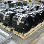
A pipe saddle is a structure consisting of a saddle and integral base that is used to support the pipe by transmitting the load or forces to the adjacent structure.

Acid Plants
Ammonia Plant
Chemical Plant
Clean Fuels

Cogeneration Plant
Cold / Cryogenc Service
Commercial
Electric Plant

Energy Facility
Ethylene Plant
Heat Recovery Steam Generation Plant
Hospital

LLDPE Chemical Plant
LNG Plant
MTBE Plant
See All

See More Images 

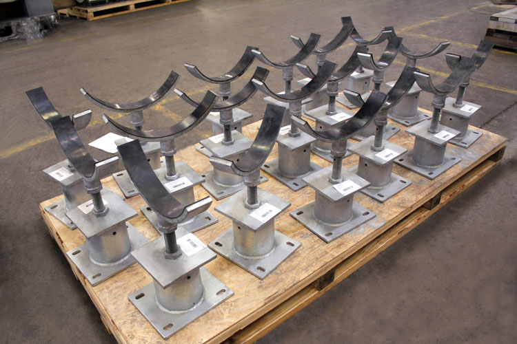
A saddle support is a support consisting of a stanchion that utilizes a curved section for cradling the pipe. Adjustable ...Continue Reading

A pipe saddle is a structure consisting of a saddle and integral base that is used to support the pipe ...Continue Reading

The pipe saddle size will be dependent upon the pipe diameter and the thickness of the insulation. 42″ Large Bore ...Continue Reading

In order to determine the appropriate insulation covering saddle, one would measure the O.D. of the pipe and insulation together ...Continue Reading

For saddle supports that do not require welding, the installation process would involve locating the saddle support in the correct ...Continue Reading


More FAQs…

Download PDF

Fig. 46: Adjustable Pipe Saddle Support

Fig46

MATERIAL: Carbon steel saddle, locknut nipple, and special cast iron reducer, assembled. Base included when specified.
SERVICE: Stanchion type support where vertical adjustment is required.
INSTALLATION: Adjustment is obtained by turning the lock-nut nipple, the lower end of the nipple, and coupling during adjustment.
ORDERING: Specify figure number, pipe size, description and finish.

*Max Load varies based on overall height

PIPE SIZEAPPROX. WEIGHT lbs. per 100ABCDEMAX LOAD*
CompleteSaddle
Only
SquareMin.Max.
2 1/29004802 1/23 1/291 1/28132,000
39205002 1/23 3/491 1/28 1/413 1/42,000
3 1/29405202 1/2491 1/28 1/213 1/22,000
4150076034 1/492 1/29 1/4143,800
5166592534 7/892 1/21014 3/43,800
61765102535 1/292 1/210 1/215 1/43,800
82020128036 7/892 1/211 3/416 1/23,800
102515177538 1/292 1/213 1/218 1/43,800
122900216039 15/1692 1/21519 3/43,800
1449203800410 15/1611316 1/420 3/45,300
1653204200412 3/811317 3/422 1/45,300
1870805100613 7/813 1/23 1/219 1/2246,700
20104808500615 3/813 1/23 1/22125 1/26,700
241300011000617 15/1613 1/2423 3/428 1/47,300
301700015000621 5/1613 1/242731 1/27,300
321810016100622 1/213 1/2428 1/432 3/47,300
362490022900624 1/213 1/2430 1/434 3/47,300

Download PDF

Fig. 48: Pipe Saddle Support with U-Bolt

Fig48

MATERIAL: Carbon steel stanchion saddle with steel U-Bolt and nuts.
INSTALLATION:
1. Slip saddle base into riser pipe.
2. If riser pipe and flange are used, flange is drilled for bolting to steel beam or floor.
3. Yoke is attached to saddle after pipe is in place.

ORDERING: Specify figure number, pipe size, description, material and finish.

PIPE SIZEAPPROX. WEIGHT (lbs. per 100)ABMAX LOAD
4107534 3/163,800
5121034 13/163,800
6127035 7/163,800
8213036 15/163,800
10257038 7/163,800
12312039 15/163,800
145000410 15/165,300
165700412 3/85,300
186400413 7/86,700
2011350615 3/86,700
2413700617 15/167,300
3014650619 1/87,300
3217400821 5/167,300
3626800824 1/27,300

Download PDF

Fig. 183: Pipe Insulation Protection Shield

183

MATERIAL: Carbon steel
FINISH: Galvanized and black
SIZE RANGE: For use with ½” thru 24” pipe with insulation thickness ½”, 3/4”, 1”, 1 ½” and 2”.
SERVICE: Recommended for outside of foam or fiber glass insulation to preclude crushing of insulation without breaking the vapor barrier.
APPROVALS: Complies with Federal Specification WW-H-171E (Type 41) and Manufacturers Standardization Society SP-69 (Type 40).
ORDERING: Specify figure number, pipe size, description, insulation thickness and finish.

Shield Size Selection Table
Insulation Thickness (in.)
SIZE1/23/411-1/22
1/21A1A
3/41A1A2A4A6A
11A2A3A5A7A
1 1/42A3A3A6A7A
1 1/22A3A4A6A7A
23A4A5A7A8A
2 1/24A5A6A7A8A
35A6A7A8A9A
3 1/28A9A10A
48A9A10A
59B10B11B
610B11B12B
813C14C
1014C15C16C
1216C17C18C
1417C18C19C
1619C20C21C
1821C22C23C
2023C24C25C
2426C27C28C

SHIELD DIMENSION
SHIELD SIZESTOCK SIZE (GAGE )APPROX. WEIGHT eachLENGTH LRADIUS R
X1A180.54120.95
1A180.69121.19
2A180.84121.44
3A180.99121.75
4A181.1122.00
5A181.3122.25
6A181.4122.50
7A181.6122.78
8A161.9123.32
9A162.7123.82
10A163.1124.32
9B164.0183.82
10B164.6184.32
11B165.1184.82
12B165.6185.38
13C1410.2245.88
14C1411.1246.38
15C1411.9247.00
16C1412.7247.50
17C1413.6248.00
18C1414.5248.50
19C1221.2249.00
20C1222.4249.50
21C1223.62410.00
22C1224.82410.50
23C1225.92411.00
24C1227.12411.50
25C1228.32412.00
26C1231.02413.00
27C1231.82413.50
28C1233.02414.00

Download PDF

Fig. 184: Pipe Covering Saddle for 1″ Insulation

Fig185

FINISH: Black, galvanized, or painted.
SERVICE : Designed to keep insulation from crushing and to reduce heat losses.
ORDERING: Specify figure number, pipe size, description, insulation thickness and finish.
NOTE: All saddles are 12” long with the side edges turned up.

FIG. 184 - 1″ INSULATION
PIPE SIZEMAX. RECOM. LOADAPPROX. WEIGHT (lb. per 100)COVERING THK.C
3/412001417/81 9/16
112001411 1/161 7/8
1 1/412001417/81 7/8
1 1/2120015112 1/8
212001671 1/162 3/8
2 1/212001671 1/162 5/8
3120018812 15/16
3 1/212002281 1/43 7/16
412002281 1/163 7/16
5120022813 15/16
6180037814 1/2

Download PDF

Fig. 185: Pipe Covering Saddle for 1 1/2″ Insulation

Fig185

FINISH: Black, galvanized, or painted.
SERVICE: Designed to keep insulation from crushing and to reduce heat losses.
ORDERING: Specify figure number, pipe size, description, insulation thickness and finish.
NOTE: All saddles are 12” long with the side edges turned up.

FIG. 185 - 1 1/2″ INSULATION
PIPE SIZEMAX. RECOM. LOADAPPROX. WEIGHT per 100COVERING THK.C
3/412002101 7/162 1/8
112002101 9/162 3/8
1 1/412002101 5/82 5/8
1 1/212002101 1/22 5/8
212002341 9/162 15/16
2 1/212002761 7/83 7/16
312002761 9/163 7/16
3 1/212003211 13/163 15/16
412003211 9/163 15/16
512003211 1/24 7/16
618004421 1/25
850005811 1/26 1/8
1050005811 9/167 1/4
1250007811 9/168 1/4
1450007811 1/28 3/4
1650008441 1/29 3/4
1850009121 1/210 3/4
20720010441 1/211 7/8
24720012311 1/213 7/8
30720013331 1/216 7/8
36720018031 1/219 7/8

Download PDF

Fig. 186: Pipe Covering Saddle for 2″ Insulation

Fig186

FINISH: Black, galvanized, or painted.
SERVICE: Designed to keep insulation from crushing and to reduce heat losses.
ORDERING: Specify figure number, pipe size, description, insulation thickness and finish.
NOTE: All saddles are 12” long with the side edges turned up.

FIG. 186 - 2″ INSULATION
PIPE SIZEMAX. RECOM. LOADAPPROX. WEIGHT per 100COVERING THK.C
3/412002761 7/82 5/8
112002762 1/82 15/16
1 1/412002761 15/162 15/16
1 1/218003182 5/163 1/2
218003192 1/83 1/2
2 1/218003192 5/164
318003582 1/164
3 1/218003582 1/44 1/2
418003582 1/164 1/2
5180035825
6180057325 9/16
8180063426 9/16
1050007652 1/167 3/4
1250009882 1/168 3/4
14500098829 1/4
1650001040210 1/4
1872001040211 3/8
2072001161212 3/8
2472001335214 3/8
3072001408217 3/8
3672001893220 3/8

Download PDF

Fig. 187: Pipe Covering Saddle for 2 1/2″ Insulation

Fig187


FINISH: Black , galvanized, or painted.
SERVICE: Designed to keep insulation from crushing and to reduce heat losses.
ORDERING: Specify figure number, pipe size, description, insulation thickness and finish.
NOTE: All saddles are 12” long with the side edges turned up.

FIG. 187 - 2 1/2″ INSULATION
PIPE SIZEMAX. RECOM. LOADAPPROX. WEIGHT (lb. per 100)COVERING THK.C
1 1/412003612 7/163 7/16
1 1/218003612 13/164
218003612 5/84
2 1/218004062 7/84 1/2
318004062 9/164 1/2
3 1/218004462 3/45
418004462 9/165
518004462 9/165 9/16
618006512 1/26 1/16
818007212 11/167 3/16
1050008202 9/168 1/4
12500010452 5/89 1/4
14500010452 1/29 3/4
16720011072 1/210 7/8
18720012392 1/211 7/8
20720012392 1/212 7/8
24720014342 1/214 7/8
30720019992 1/217 7/8
36720020202 1/220 7/8

Download PDF

Fig. 188: Pipe Covering Saddle for 3″ Insulation

Fig188

FINISH: Black , galvanized, or painted.
SERVICE: Designed to keep insulation from crushing and to reduce heat losses.
ORDERING: Specify figure number, pipe size, description, insulation thickness and finish.
NOTE: All saddles are 12” long with the side edges turned up.

FIG. 188 - 3″ INSULATION
PIPE SIZEMAX. RECOM. LOADAPPROX. WEIGHT (lb. per 100)COVERING THK.C
218004493 1/84 1/2
2 1/218004493 3/85
318004913 1/165
3 1/218004913 5/165 9/16
418004913 1/165 9/16
518004913 1/166 1/16
6180077336 9/16
818007733 1/87 11/16
1050008843 1/168 3/4
12500011353 1/169 3/4
1450001135310 1/4
1672001330311 3/8
1872001330312 3/8
2072001342313 3/8
2472002034315 3/8
3072002137318 3/8
3672002158321 3/8

Download PDF

Fig. 189: Pipe Covering Saddle for 4″ Insulation

Fig189

FINISH: Black , galvanized, or painted.
SERVICE: Designed to keep insulation from crushing and to reduce heat losses.
ORDERING: Specify figure number, pipe size, description, insulation thickness and finish.
NOTE: All saddles are 12” long with the side edges turned up.

FIG. 189 - 4″ INSULATION
PIPE SIZEMAX. RECOM. LOADAPPROX. WEIGHT (lb. per 100)COVERING THK.C
418006114 1/166 9/16
518006114 3/167 3/16
6180010204 1/87 11/16
8180010204 3/168 11/16
10500010834 1/169 3/4
12500013984 1/810 3/4
1450001398411 1/4
1672001530412 3/8
1872001530413 3/8
2072002279414 3/8
2472002305416 3/8
3072002396419 3/8
3672002413422 3/8

Download PDF

Fig. 2000: Heavy Duty Pipe Saddles

Fig. 2000: Heavy Duty Pipe Saddles a
Fig. 2000: Heavy Duty Pipe Saddles
NOTE:
1. Tolerances: R=1%-0
Other Dimension – 1/16, Except Plate Thickness – 1/32 Angle – 1 1/4 Deg.
2. Full Encirclement Saddle Plates shall be used on all cross-country pipelines, on Grade X-46 or higher strength pipe, and on all station pipework designed to operate at or in excess of 90% of Min. Specified yield strength. Segmental Saddle Plates shall be used on station pipework designed to operate at less than 50% of min. yield strength.
3. For maximum spans of pipelines using saddles use Standard Engineering Practice.
4. Pipe Support of Sleeper Under the Saddle shall be designed to accommodate full axial movement of the pipeline and saddle.
5. Vent hole 1/4 to be drilled in each segment of saddle.

HOW TO ORDER: Specify figure number, pipe size, and description.

PIPE SIZERADIUSDIMENSIONSAPPROX.
WEIGHT lbs.
R
ABCD
E
FType 1Type 2
20
10
20 1/2
2 3/8
7
4
1/2
3/8
165
90
22
11
22
2 5/8
7 1/2
4
1/2
3/8
185
100
24
12
23  1/2
2 7/8
8
4
1/2
3/8
195
105
26
13
25 1/2
3 3/8
8 1/2
4
1/2
3/8
210
110
28
14
27
3 5/8
9
4
1/2
3/8
230
120
30
15
29
4
9 1/2
4
5/8
1/2
315
175
32
16
31
4 1/2
10
4
5/8
1/2
330
190
34
17
32
5
10
4
5/8
1/2
355
200
36
18
34
5
11
4
5/8
1/2
375
210
38
19
36
6
11
4
5/8
1/2
395
220
40
20
38
6
12
4
5/8
1/2
420
235
42
21
40
6
13
4
5/8
1/2
440
250
48
24
46
6
16
4
5/8
1/2
510
285
54
27
52
7
19
4
5/8
1/2
575
320
60
30
58
8
20
4
5/8
1/2
625
360

Download PDF

Heavy Duty Pipe Saddles

Fig260

FINISH: Black, galvanized, or painted.
SERVICE: General piping
ORDERING: Specify figure number, pipe size, description, finish and height.

*Max load varies based on height.

PIPE
SIZE
PLATE
SIZE A
PIPE
SIZE B
PIPE
SIZE C
PLATE
SIZE D
MAX LOAD*
3
5 x 1/41 1/2
2 1/2
8 x 8 x 3/82,000
4
6 x 1/42
3
8 x 8 x 3/83,800
6
6 x 1/42
3
8 x 8 x 3/83,800
8
7 x 3/83
4
8 x 8 x 1/23,800
10
7 x 3/83
4
8 x 8 x 1/23,800
12
9 x 3/84
6
10 x 10 x 3/43,800
14
9 x 3/84
6
10 x 10 x 3/45,300
16
11 x 3/86
8
12 x 12 x 3/45,300
18
11 x 3/86
8
12 x 12 x 3/46,700

Download PDF

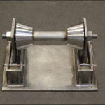
Fig. 210: Pipe Roller Chair

Fig. 210: Pipe Roller Chair

MATERIAL: Cast iron roll, steel roll rod, steel continuous thread rods and hex nuts.
SERVICE: For support of pipe where horizontal movement due to expansion and contraction will occur and where vertical adjustment up to 6” may be necessary.
HOW TO SIZE:
1. If roll is to support bare pipe, select the size directly from nominal pipe size.
2. If used with pipe covering protection saddle, see pipe insulation chart for size of pipe roll.
3. If roll is to support covered pipe, the O.D. of the covering should not be greater than the O.D. of the pipe for which the roll was designed.

ORDERING: Specify figure number, pipe size, description and finish.

PIPE SIZE
MAX. RECOM.
LOAD (lb.)
WEIGHT
(lb. per 100)
A
B
C
D
E
F
STEEL SIZE G
BOLT SIZE H
2600
110
3 1/16
1 9/16
1 1/2
3/8
1 1/4
3 7/8
1/4 x 1 1/4
3/8 x 1 1/4
2 1/2
660
136
3 1/2
1 7/16
1 5/8
1/2
1 1/4
4 3/4
1/4 x 1 1/43/8 x 1 1/4
3
700
164
3 15/16
2 3/16
1 3/4
1/2
2
5 1/2
1/4 x 1 1/4
3/8 x 1 1/4
3 1/2750
250
4 1/22 1/2
2
1/2
2
6
3/8 x 1 1/2
1/2 x 1 1/2
4
750
305
5 1/16
2 3/4
2 5/16
1/2
2
6 1/2
3/8 x 1 1/2
1/2 x 1 1/2
5
750
428
5 15/16
3 7/16
2 1/2
5/8
2 1/2
7 7/8
3/8 x 1 1/2
1/2 x 1 1/2
6
1070
535
6 3/4
4
2 3/4
3/4
3 1/4
9 1/23/8 x 1 3/4
1/2 x 1 1/2
8
1350
690
8 1/4
5 1/43
7/8
4
11 3/4
3/8 x 2
1/2 x 1 1/2
10
1730
1263
9 7/8
6 1/43 5/8
7/8
5
14 1/4
1/2 x 2
1/2 x 1 1/2
12
2400
2060
11 9/16
7 7/164 1/8
1
6
16 1/21/2 x 2
1/2 x 1 1/2
14
3130
2680
13 1/16
8 5/164 3/4
1 1/87
18 5/8
1/2 x 2 1/2
5/8 x 2
16
3970
4575
14 3/8
9 3/85
1 1/48
21
5/8 x 2 1/2
5/8 x 2 1/2
18
4200
4700
15 5/8
10 3/85 1/4
1 1/49
22 7/85/8 x 2 1/2
5/8 x 2 1/2
20
4550
6200
17 1/4
11 1/25 3/4
1 3/810
25 1/25/8 x 3
3/4 x 3
24
6160
9990
20 13/1613 13/167
1 1/212
30
3/4 x 3
3/4 x 3

Download PDF

Fig. 215: Adjustable Pipe Roll Support

Fig215

MATERIAL: Cast iron roll and sockets, steel roll rod, steel continuous thread rods and hex nuts.
SERVICE: For support of pipe where horizontal movement due to expansion and contraction will occur and where vertical adjustment up to 6” may be necessary.
SIZE: If roll is to support bare pipe, select the size directly from nominal pipe size.
ORDERING: Specify figure number, pipe size, description and finish.

PIPE SIZEAPPROX. WEIGHT lbs. per 100ABCDH
11133/831 1/29 1/21 1/16
1 1/41173/83 3/81 7/89 1/21 1/4
1 1/21203/83 5/82 1/89 1/21 3/8
21253/84 1/82 5/89 1/21 5/8
2 1/22291/24 7/83 1/89 1/21 15/16
32421/25 1/23 3/49 1/22 1/4
3 1/22691/26 1/84 1/2102 9/16
43755/86 3/44 3/4102 13/16
54695/88 1/165 13/16103 7/16
67573/49 9/166 7/8114
811017/811 15/168 7/811 3/45 1/8
1013747/814 1/161111 3/46 3/8
1219367/815 13/1612 1/211 3/47 7/16
143116117 3/414 1/411 3/48 3/8
1642451 1/819 3/416 1/4189 7/16
1846551 1/821 7/818 1/41810 1/2
2066231 1/424 1/420 1/41811 5/8
24102521 1/228 5/824 1/42414
30186811 7/835 1/230 1/42417 7/16

Download PDF

Fig. 230: Pipe Roller Chair

Fig230

MATERIAL: Cast iron roll and stand.
SERVICE: For support of piping that expands and contracts longitudinally and where vertical adjustment is not necessary.
HOW TO SIZE:
1. If roll is to support bare pipe, select size from nominal pipe size.
2. If used with pipe covering protection saddle, see FIG. 183 for size of pipe roll.

INSTALLATION: Two cored holes “I” for anchorage bolting purpose.
ORDERING: Specify figure number, pipe size, description and finish.

PIPE
SIZE
2 – 3 1/24 – 68 – 1012 – 1416 – 20243036 – 42
MAX. RECOM. SIZE LOAD, lbs.3909502100307549806100750012000
COMPLETE (APPROX. WEIGHT, lbs per 100)6408851530281039654950992515200
ROLL AND ROD (APPROX. WEIGHT, lbs per 100)9013553010101565195033905700
ROLL ONLY (APPROX. WEIGHT, lbs per 100)701104408501270145024004100

PIPE SIZEABCDEFGHIJKLMNP
23 7/1642 1/22 11/163/41 1/161 3/49/1611/21/48 7/165 1/223 1/2
2 1/23 7/8
34 1/8
3 1/24 3/8
44 11/164 1/42 5/837/81 1/1629/1611/21/49 15/16634 3/4
55 3/8
66
8753/41 1/81 1/22 1/43 3/83/415/83/88 1/2838 5/8
109 3/4
129 1/16611 7/1612 1/23 3/47/813/43/811 1/168311 1/4
1411 7/8
1610 1/46 1/21 3/81 7/81 1/42 3/164 1/41 1/4113/161/2139413 5/8
1814 5/8
2015 5/8
2411 3/86 1/211 9/161 1/434 3/81 1/2113/161/213 3/89417 3/4
3014 1/481 3/82 3/81 1/23 1/25 1/81 7/811 1/161/21711521 7/8
361791 1/22 7/161 1/245 3/42 1/811 5/163/42012625 3/4
4228 7/8

Download PDF

Fig. 240: Adjustable Pipe Roller Stand

Fig240

MATERIAL: Cast iron base plate, stand and roll, steel adjusting screws.
SERVICE: To support pipe lines where vertical and lateral adjustment during installation may be required in addition to provision for expansion and contraction.
HOW TO SIZE: If roll is to support bare pipe, select the size from nominal pipe size (see below).
ORDERING: Specify figure number, pipe size, description and finish.

SIZE (inches)MAX. RECOM. LOAD, lbs.WEIGHT per 100
2 — 3 1/23901525
4 — 69501930
8 — 1021003205
12 — 1430755115
16 — 2049807130
2461008700
30750016615

PIPE SIZEABCDD1EFGHJJ1KLM MAX.NPRSTU
MIN.MAX.
25 1/85 3/81 3/41 3/46 7/88 3/85 1/22 3/41 7/81/23 7/86 3/8111/167/811/415/83 7/164
2 1/25 3/85 5/82 1/8
35 3/462 3/8
3 1/266 1/42 5/8
46 1/272 3/42 1/168 1/89 7/85 3/43 3/42 1/161/25 1/87 3/817/81 1/811/415/84 11/164 1/4
577 1/23 3/8
67 5/88 1/84
810 3/811 5/85 1/43 7/1610 5/86 3/463 1/43/47 3/817/81 3/41 1/83/813/475
1011 1/212 3/46 3/8
121314 1/47 1/23 7/8138847/89 1/217/81 3/41 1/83/817/89 1/166
1413 5/814 7/88 1/8
1615 1/416 5/89 3/84 1/414 5/88 5/894 1/21 1/411 1/8111 7/81 1/45/81 3/16110 1/46 1/2
1816 3/817 3/410 3/81 3/8
2017 3/818 3/411 3/8
2419 5/82113 3/84 3/815 3/48 5/8104 7/161 3/812 1/411 1/81 7/81 3/85/81 13/16111 3/86 1/2
302426 3/416 3/45 1/819 1/410 1/212 1/25 1/21 3/415 3/411 1/23 1/41 5/83/41 3/81 1/414 1/48

Download PDF

Fig. 182: Non-Metallic Wear Pad

Fig182

Fig182b

MATERIAL: Vinyl resins
FINISH: As-Is
SIZE RANGE: 1/2″ thru 48″
SERVICE: Recommended to protect un-insulated pipe from the metal supporting structure. Pad to be secured to pipe using epoxy adhesive.
MAX TEMP.: 400°F
ORDERING: Specify figure number, pipe size, description, length and angle.

PIPE SIZETHICKNESSLENGTH LANGLE ARADIUS R
1/21/412907/16
3/41/412909/16
11/412905/8
1 1/41/412907/8
1 1/21/412901
21/412901 3/16
2 1/21/412901 7/16
31/412901 13/16
3 1/21/412901 3/4
41/412902 1/4
51/412902 13/16
61/412603 5/16
81/412604 5/16
101/412605 3/8
121/412306 3/8
141/412307
161/412308
181/412309
201/4123010
243/8123012
26-483/812301/2 of Pipe O.D.


Top