For non-piping engineers, understanding the fundamentals of piping stress is critical for ensuring the structural integrity of industrial facilities. A comprehensive piping analysis evaluates how factors such as temperature changes, internal pressure, and dynamic forces affect the piping system and its connected equipment.
The process of pipe stressing identifies potential mechanical failure points before they occur. By designing adequate pipe flexibility into the network, engineers can safely manage the severe pipe stress generated by hot or cold thermal piping.
To accurately calculate these complex loads, movements, and support requirements, professionals rely on advanced pipe stress analysis software to guarantee compliance with industry safety codes and ensure reliable operation.
Pipe Stress Analysis for Non-Piping Engineers
Pipe stress analysis deals with issues that arise from the thermal growth of piping. It is a niche area of engineering that is not widely taught in schools. 40-48% of the engineering labor hours in a new plant build go towards piping, and the high-temperature piping, where pipe stress analysis is required, is the most engineered portion of the piping system.
The challenge PT&P has seen is that the majority of people who tackle pipe stress-related issues and maintenance daily do not have a background in pipe stress engineering. In addition, most plant maintenance, engineering, inspection, and turnaround personnel have a broad set of responsibilities, and pipe stress may be a minor portion of these responsibilities. PT&P has put this primer together for those who want a basic understanding without getting into the detailed engineering and knowledge of how to run a pipe stress program, such as Caesar II or AutoPipe.
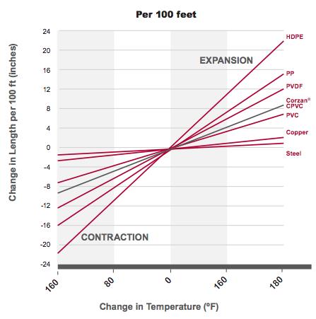
As can be seen from the chart below, the issue of thermal expansion can be even greater with some non-metallic materials used in piping systems.
The Importance of Piping Analysis and System Reliability
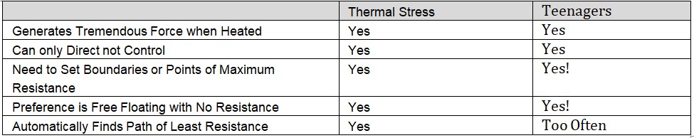
Thermal growth is too powerful to be contained. The key to pipe stress engineering is managing and directing thermal growth. Directing and managing thermal growth is possible because thermal growth will always find the path of least resistance. Effective pipe stress analysis designs a path of least resistance that can effectively absorb the required thermal growth while continuing to support the piping and keep loads at key points in the system, such as nozzles, below the maximum allowable load. As the father of 2 teenagers, I have found one of the easiest ways to think about the challenges of thermal growth in piping is comparing it to my teenagers.
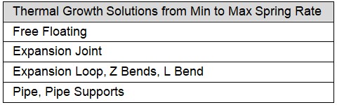
The path of least resistance is defined by the most flexible elements of the piping system from anchor to anchor. Below is a view of elements from most to least flexible that are used by pipe stress engineers:
Using Pipe Stress Analysis Software for Accurate Calculations
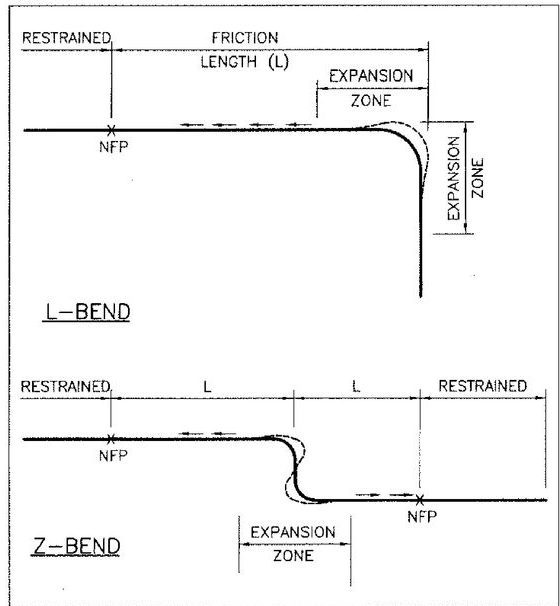
The charts below show how expansion loops, Z-bends, and L-bends deform under thermal growth to absorb thermal expansion. Because all of these almost always have less flexibility than an expansion joint, they require more room to absorb the same level of thermal growth.
 |
 |
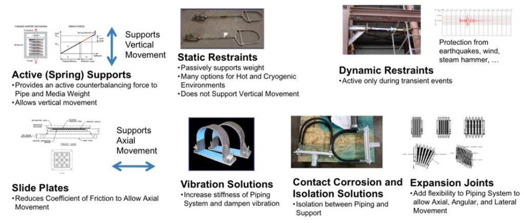
Because Piping Technology and Products started as a pipe stress engineering company, we are the only global provider that manufactures a complete line of major solutions for pipe stress. The following is a view of the different solutions we offer:
The only way to manage thermal growth in larger piping systems is to use anchors (points of maximum resistance where the piping is tied down to the structure) to break thermal growth management into smaller sections of piping. It is important to note that equipment is typically anchored and therefore acts as an anchor. However, the goal with equipment is to minimize loads at the nozzle.
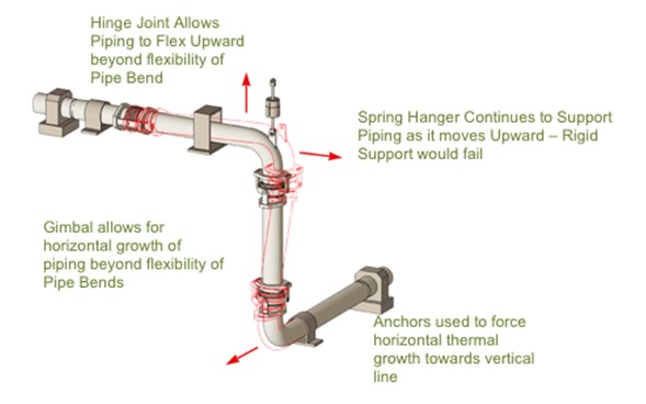
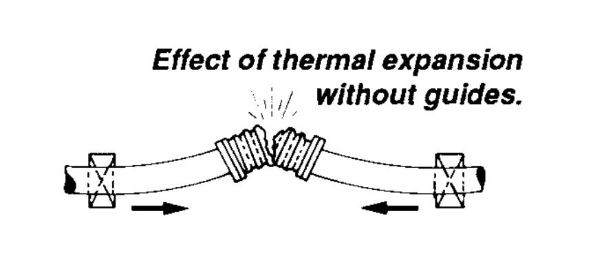
The diagram below shows expansion joints, springs, guides, and anchors. In this case, thermal growth is leading horizontal growth on the upper and lower sections of piping and vertical growth on a vertical run of piping. The system is anchored at the ends. Thermal growth will move away from the anchors, which means it will move towards the vertical run of piping on the upper and lower horizontal lines. The expansion joints facilitate the movement of piping shown in the red outline, which is driven by thermal expansion on the various runs of piping. The variable spring support allows for the load of the vertical piping to be carried even when the pipe moves upward, as shown in the red dotted lines. The guides are used to ensure proper movement of the piping and to prevent the expansion joints from buckling or squirming.
Plant Maintenance and Engineering Tools
Many situations require evaluation without the benefit of a pipe stress model. In this case, some keys to initial assessment:
- Find the Anchors – The anchors will determine the direction of movement in the area to be assessed.
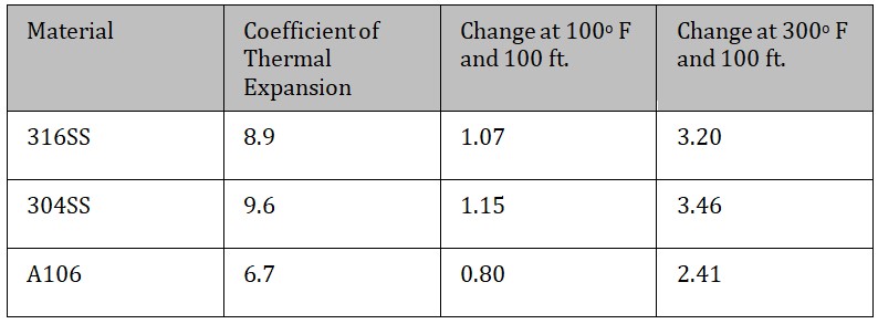
- Estimate Thermal Growth – Between the anchors, estimate the X, Y, and Z lengths of piping and use the basic thermal growth formulas per 100 ft and 100°F to determine movements.
- Assess Key Thermal Stress Items – Assess how spring supports, expansion joints, slide plates, and other stress-related items are being used in the system to direct and/or absorb the thermal growth. For example, hot and cold positions on spring supports will provide the total movement allowed by the springs and also provide the expected up or down movement of the piping at that location.
- Assess Differences from Design Movements and Elements not Functioning – Key items such as spring supports or expansion joints that are not functioning as designed will place stress/load elsewhere in the system. If the movement of the piping looks different from what is designed, it is an indication of the force of thermal growth being poorly managed and potentially causing issues at the nozzles or piping not being properly supported.
Pipe Stress Component Glossary for Dummies
Anchors (point of maximum resistance to movement) – This is a point where the pipe is secured to the structure, making it extremely difficult to move. The purpose of an anchor is to force all thermal movement to occur away from the anchor towards points in the piping system that are more flexible. This is one means to control and direct thermal growth. NOTE: Equipment is typically anchored and therefore acts as an anchor in the system.
Guide – This is the support that allows the pipe to move freely in one direction while restricting movement in other directions, therefore ensuring thermal growth occurs in the desired direction.
Slide Plate (used to reduce the coefficient of friction) – Slide plates are used to reduce the coefficient of friction in order to ensure thermal growth occurs without damage from friction between the pipe and supports, such as the thermal growth of pipe pulling supports off their underlying structure.
Variable Spring Support –Used to provide continuous support to the pipe as it moves vertically in scenarios where a rigid support would either not rise to support the pipe or would not move downward to get out of the way of thermal growth. Variable supports allow up to 25% load variation.
Constant Spring Support – Same function as a variable spring support, but with only up to 6% load variation.
Snubber – Functions similarly to a seat belt, allowing free movement except in the case of an event (such as seismic, water hammer, slug, etc.) at which point it becomes a rigid support.
Sway Brace – Uses a spring to dampen vibration. Spring compresses in both directions.
Sway Strut – Allows movement in 2 planes but remains rigid in 1 plane of movement. Used to ensure the separation of 2 items, such as a pipe and a structure, in the case of an unexpected event.
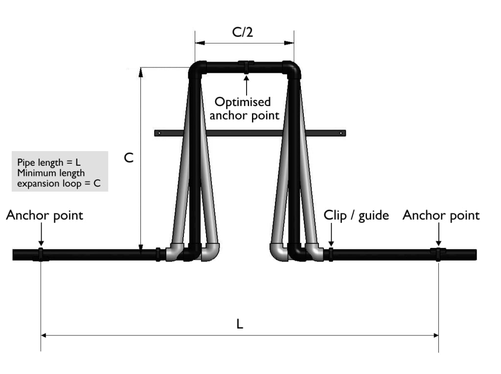
Expansion Loop – A picture of an expansion loop is shown below. Expansion loops are placed into piping systems in order to absorb thermal growth through deformation, as shown in the picture. This keeps thermal growth from expanding into anchors.

Z and L Bends – Changes in the direction of piping or bends are used to absorb thermal growth. A picture of a Z and L bend and associated deformation is shown below.
Expansion Joint – An expansion joint is a piece of piping in which convolutions have been punched in order to have the piping obtain the properties of a spring with much lower spring rates than the rest of the piping system. In addition to having convolutions punched, expansion joints are typically much thinner than the rest of the piping system.
FAQs
Q: What exactly is piping stress?
A: Piping stress refers to the internal forces and pressures exerted on a piping system by thermal expansion, internal fluid pressure, external dynamic loads, and the weight of the pipes themselves.
Q: Why is a comprehensive piping analysis necessary for a facility?
A: A comprehensive piping analysis is essential to ensure that the system can safely withstand all operational and environmental loads. Proper analysis helps prevent structural failures, dangerous leaks, and equipment damage by verifying that stresses, movements, and support conditions remain within acceptable design limits.
Q: How does pipe flexibility protect the piping system?
A: Designing adequate pipe flexibility into the layout—such as incorporating expansion loops or adjustable supports—allows the piping to expand, contract, and move naturally. This helps prevent excessive stress on the pipe wall and connected equipment, reducing the risk of fatigue, leaks, or structural damage.
Q: What role does pipe stress analysis software play in the engineering process?
A: Engineers use advanced pipe stress analysis software to simulate complex load conditions and thermal movements within a piping system. These digital models help verify that the design complies with applicable ASME codes and safety standards before fabrication, reducing the risk of failures and ensuring reliable system performance.
Q: How does thermal piping differ from standard cold lines?
A: Thermal piping transports extremely hot or cold process fluids, which causes significant expansion or contraction as temperatures change. Because of these thermal movements, thermal piping systems require specialized supports and design considerations to control pipe stress and protect connected equipment.
Q: What happens during the analytical process of pipe stressing?
A: The process of pipe stressing involves calculating and evaluating how piping materials and components respond to operational loads such as pressure, temperature changes, weight, and external forces. These evaluations help determine stress levels, movement, and proper support placement to ensure the system maintains structural integrity and operates safely within design limits.