Most hydraulic snubbers have a piston which is relatively unconstrained in motion at low displacement rates. At high displacement rates the piston “locks up”, that is, the force required to move the piston increases substantially, usually as a result of the closing of a valve.
Hydraulic snubbers are specialized dynamic restraints designed to protect critical industrial systems from sudden shock loads caused by seismic events, turbine trips, or safety valve discharge. Unlike rigid supports, a hydraulic snubber uses a fluid-filled cylinder and control valve to allow gradual displacement for thermal expansion while locking instantly when velocity thresholds are exceeded. This unique functionality makes them essential for high-load applications where standard rigid struts would fail or restrict necessary movement.
Understanding the mechanics of snubbers in piping networks is vital for maintaining system integrity; these units act as a safety fuse, converting the piping into a rigid structure only during the transient shock event. Whether for nuclear power generation or petrochemical processing, selecting the right pipe snubber ensures your infrastructure withstands unpredictable dynamic forces without compromising daily operational flexibility.
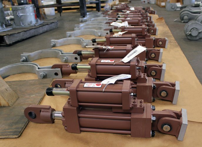
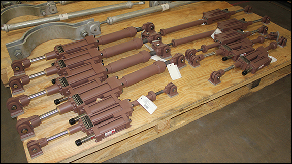
Hydraulic Snubber and 3-Bolt Clamp Assemblies for a Refinery Expansion Project
140,700 lb. Load Hydraulic Snubbers
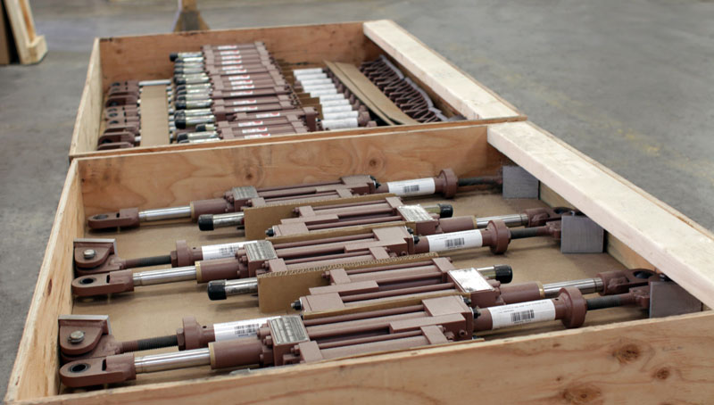
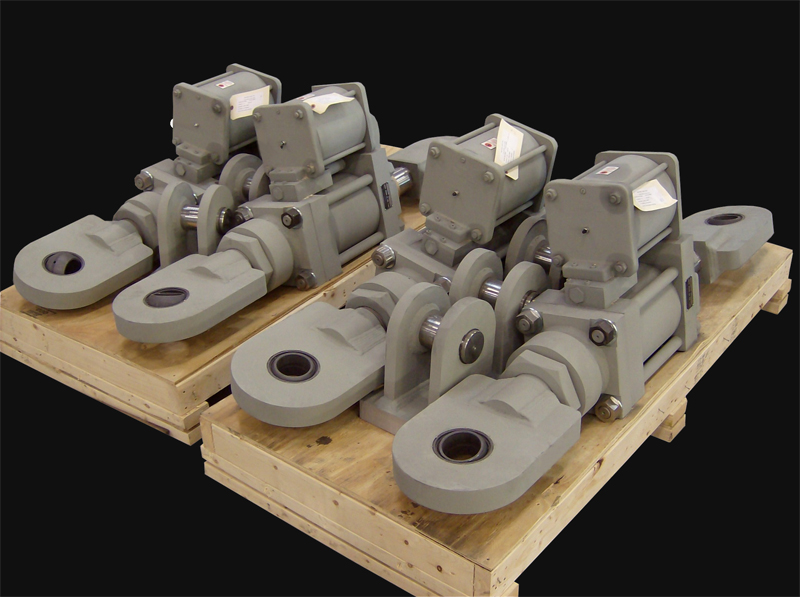
Snubbers with Yoke Clamps for a LNG Plant
Hydraulic Snubbers with Yoke Clamps for a LNG Plant
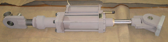
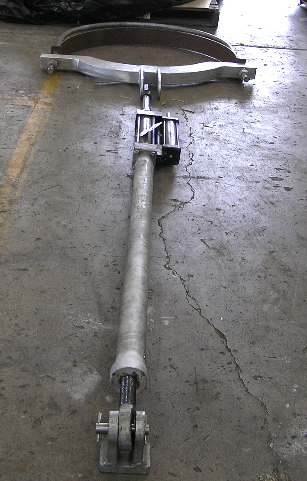
12,500 lb. Load Hydraulic Snubber and 24 Alloy Clamp Assembly
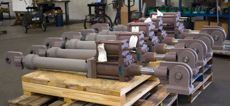
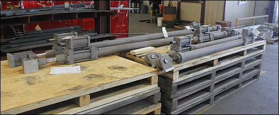
Hydraulic Snubbers Designed for an LNG Facility in Texas
Hydraulic Snubbers Designed for LLDPE Chemical Plant
Hydraulic Snubbers for an Ammonia Plant in Louisiana
Hydraulic Snubber Designed for a Gas Turbine in a Natural Gas-Fired Combined Cycle Generating Power Plant
Follow these four steps when inspecting a hydraulic snubber: Inspect welded attachments Inspect the piston Inspect the fluid level Inspect …Continue Reading
Q: What is the primary function of a hydraulic snubber in an industrial system?
A: A hydraulic snubber is a dynamic restraint device designed to control the movement of pipe and equipment during abnormal dynamic conditions. It allows free movement during normal thermal expansion but locks up instantly under a rapid impulse load, such as an earthquake or a fluid hammer.
Q: Why are snubbers in piping systems considered critical safety components?
A: Snubbers in piping systems act as “shock absorbers” that protect the structural integrity of the line. Without them, sudden shock forces could shear bolts, rupture pipes, or damage sensitive nozzle connections. They ensure the system remains rigid during a crisis event while remaining flexible during daily operation.
Q: How does a pipe snubber differ from a standard rigid strut?
A: A rigid strut locks the pipe in a fixed position, preventing movement in any direction at all times. In contrast, a pipe snubber allows gradual displacement due to temperature changes. It becomes “rigid” only when it detects a velocity change exceeding its design threshold.
Q: What maintenance is required for a hydraulic snubber?
A: Because a hydraulic snubber relies on a fluid reservoir and internal valves to function, it requires periodic inspection to detect fluid leaks, seal degradation, and proper piston rod movement. Maintaining the correct fluid level is essential for ensuring the device locks correctly under load.
Q: When should I specify a pipe snubber instead of a spring hanger?
A: You should specify a pipe snubber when you need to restrain dynamic forces (such as vibration or seismic shock) while still accommodating thermal growth. A spring hanger supports the weight of the pipe (gravity load), whereas a snubber is designed to restrain motion (dynamic load).
The style “AD” Hydraulic Shock Arrestor is a manifold design hydraulic component consisting of a high pressure main cylinder, a flow control section which contains dual stage velocity sensitive poppet valves, and a spring energize reservoir.
Application:
For use on piping systems or equipment when unrestrained thermal movement must be allowed, but which must be restrained during impulsive or cyclic disturbance. The unit is not effective against low amplitude, high frequency movement. The preferred usage with standard settings is to prevent destructive results due to earthquakes, flow transients, or wind load. Special settings are available to absorb the continuous thrust resulting from safety valve blow-off or pipe rupture.
Size Range:
PTP offers seven sizes with cylinder bores of 1 1/2 to 8 inches. These units have a normal load range of 3,000 lbs. to 130,000 lbs. All are made to include reservoirs in 6, 12, or 18 inch strokes, except the 1 1/2 inch size. The 1 1/2 inch size is offered only in 6 & 12 inch strokes only. Snubbers, as they are sometimes referred to, are available with remote reservoirs.
Size Selection:
The selection of size depends on the anticipated force and thermal movement of the protected piping or equipment. It is recommended that the selected cylinder stroke be a minimum of the anticipated thermal movement, plus 20%.
Basic Operation:
The piston rod is free to move in either direction with no restrictions to the fluid flow for all piston velocities up to the activation velocity. At activation velocity the poppet valve, internal to the snubber, closes. Closure of the poppet in either tension or compression greatly reduces the fluid flow through grooves in the poppet at rated design capacity of the unit is termed the “ bleed rate”. When the applied velocity of the unit becomes zero the poppet valve opens once again, allowing free piston movement.
Standard Design Features:
– Piping and/or equipment movement is controlled by tamperproof dual stage flow control poppets designed with self-cleaning orifices.
– Furnished as a complete, compact and efficient unit, ready for immediate use.
– Manifold configuration requiring no external piping.
– Spherical, self-aligning ball bushings allow for ±5º of angular motion or misalignment.
– Stable premium grade, antiwear hydraulic fluid.
– Pressurized hydraulic reservoir allows mounting in any spatial orientation.
– Virtually no resistance to normal thermal movements of the piping.
– Large restraining forces compared to size.
– Functions in restraining tension and compression loads.
– Designed for continuous operation up to 200°F with brief transients to a maximum of 300°F.
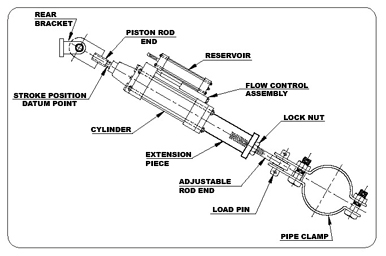
– Stroke position is measured from a machined groove located at the piston rod wrench flats.
– Fluid Level in the unit, thereby eliminating estimate of reserve fluid level.
Optional Design Features:
– Remote Reservoir Mounting
– The snubber’s pressurized reservoir can be remotely mounted for inaccessible locations.
– Integral Relief Valve- A non-adjustable valve, which is factory preset at 133%, or 200% of rated load.
– Protective Boot- Installed over piston rod for protection against corrosive or outdoor environments.
– Rigid Stud Application- When no thermal growth is anticipated after lock-up, an optional poppet valve, without bleed, can be furnished. Must be ordered with optional integral relief valve.
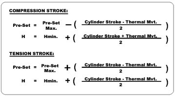
Factory Pre-set:
The units are shipped from the factory complete, tested, reservoir filled to capacity and piston rod preset to mate with pin to pin installation dimension. To determine factory pre-set dimension perform the following calculations.
HYDRAULIC SNUBBERS
In addition to the mechanical equipment described in this brochure, Anchor/Darling Enterprises also offers a complete line of hydraulic snubbers.
• hydrA/Damp — Our advanced design, corrosion resistant hydraulic snubber, for superior performance within many environments.
• B-P Style — Our well-established (formerly Bergen-Paterson) manifold design hydraulic snubber, eliminates external tubing and its pressurized reservoir allows installation in any spatial orientation.
• Non-Nuclear — Our commercial snubber design, for use within fossil/co-gen/petro-chernical plants that require proven performance at economical prices.
For additional information on any of our hydraulic or mechanical snubbers, contact the regional office nearest you.