Sway Braces

A sway brace is a device used for controlling vibration, absorbing shock loadings; guiding or restraining the movement of pipe resulting from thermal expansion; bracing a pipe line against sway.

Types & Sizes

Technical Information

Installation & Maintenance

Request a Quote


Ammonia Plant
Chemical Plant
Clean Fuels
Commercial

Electric Plant
Energy Facility
Ethylene Plant
LLDPE Chemical Plant

LNG Plant
MTBE Plant
Natural Gas Combined Cycle Facility
Natural Gas Processing & Separation

Oil Refinery
Oil Sand Mine
Paper Manufacturer
See All

See More Images

Free stroke for a sway brace refers to an amount of movement which would result in no resistance. This can ...Continue Reading

A sway brace is a device that is recommended for controlling vibration, absorbing shock loadings, guiding or restraining the movement ...Continue Reading

Either sway braces or sway struts can be used to suppress swinging of the pipeline. Note that sway braces permit ...Continue Reading

Because the strut assembly consists of basically two rods joined by a structural steel member, once the strut’s overall length ...Continue Reading


More FAQs…

General Dimensions & Specifications

Download Sway Braces General Information

SIZE RANGE: For pipe sizes 2 inches through 24 inches.
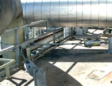
SERVICE: Recommended for controlling vibration, absorbing shock loadings; guiding or restraining the movement of pipe resulting from thermal expansion; bracing a pipe line against sway.
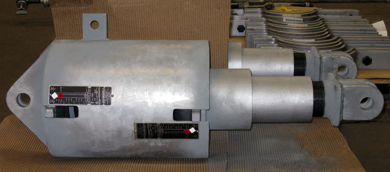
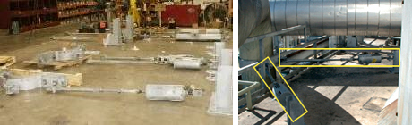
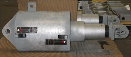
INSTALLATION: The vibration control and sway brace is shipped ready for installation. The rod coupling rotates with slight resistance and the tension test collar can be rotated by hand while holding the rod stationary.
ADJUSTMENT: The sway brace should be in the neutral position when the system is hot and operating, at which time the tension test collar should be hand tight. If it is not, the sway brace should be adjusted to the neutral position by use of the load coupling. The screws in the tension test collar need not be loosened, since they serve only to secure it to the load coupling.
FEATURE:
• Vibration is opposed with an instantaneous counter force bringing the pipe back to normal position.
• A single energy-absorbing pre-loaded spring provides two way action.
• One spring saves space and simplifies design.
• Spring has 3-inch travel in either direction.
• Accurate neutral adjustment assured.
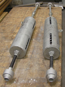
• Enclosed spring excludes dirt and gives a clean, compact appearance.
SPECIFICATION: Fulfills the requirements of the ASA Code for Pressure Piping as to fabrication details and materials.
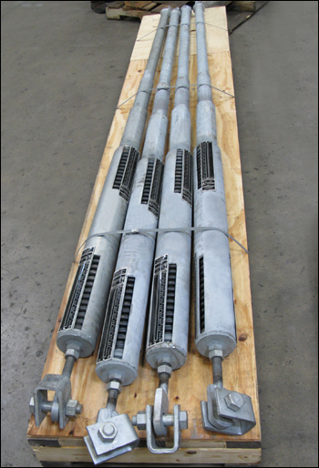
ORDERING: Specify figure number, size, description and overall dimension.

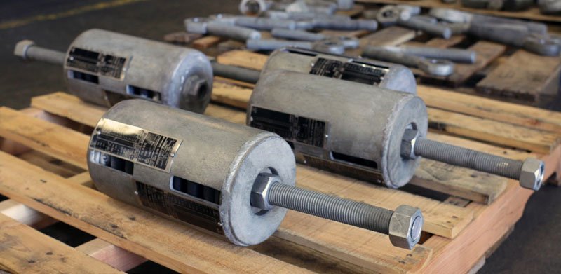
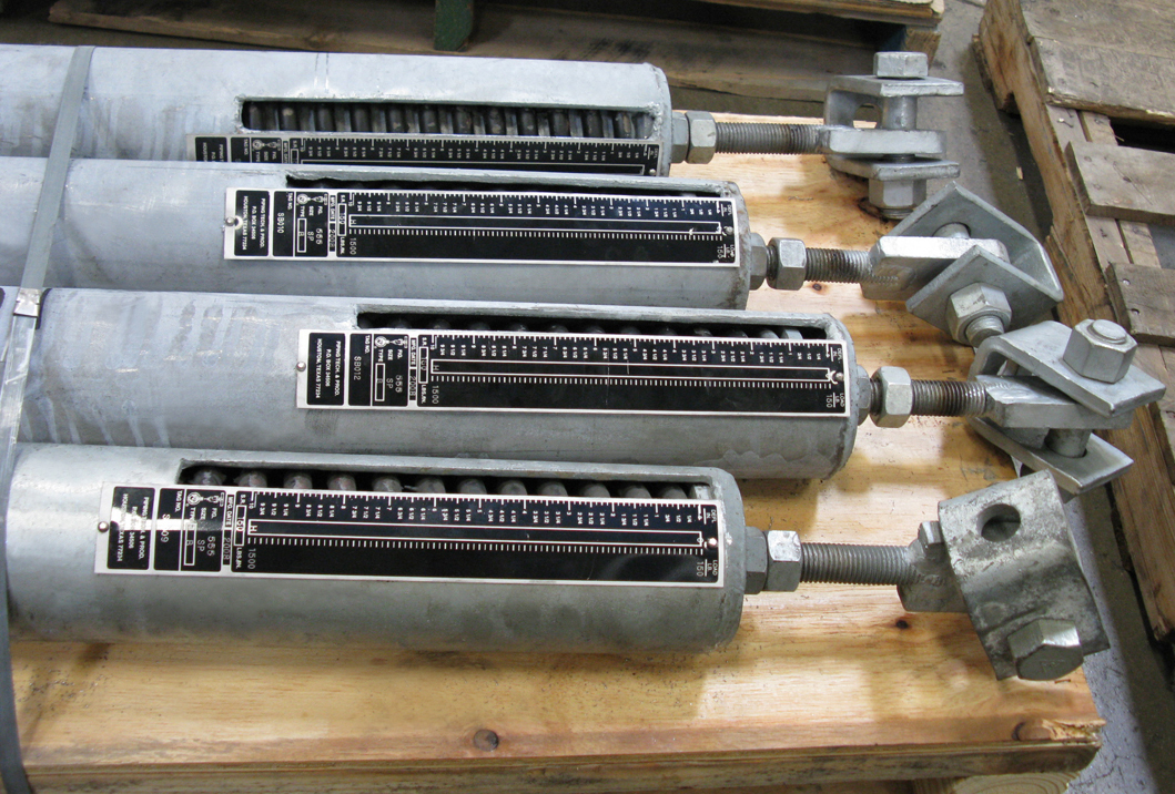
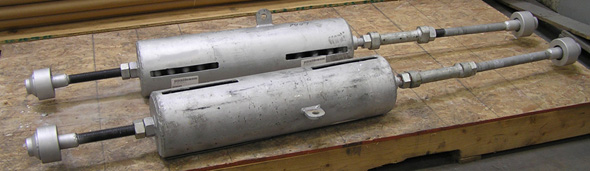
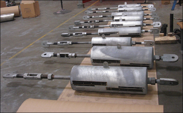
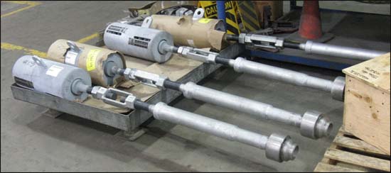
VIBRATION CONTROL AND SWAY BRACE

Size Selection:
The vibration control and sway brace gives full deflection forces from 200 lb. to 1,800 lb. and has initial pre-compressed spring forces from 50 lb. to 450 lb. to dampen vibrations, oppose pipe sway and absorb shock forces.

The exact amount of energy needed to control piping should be in proportion to the mass, amplitude of movement, and nature of disturbing forces acting on the pipe. When it is possible to calculate the exact restraining force required, the size of the vibration control and sway brace capable of providing this force should be selected.

To simplify the selection of size, engineers have designed the vibration control and sway brace in three sizes that are readily related to nominal pipe size. For pipe sizes 3-1/2 inch and smaller, the small size is recommended; for 4 to 8-inch, the medium size; and for 10-inch and larger, the large size.

Important:
Rod lengths should be cut and final tension of adjustments made for the hot or operating position of the pipe. If, with the pipe in its hot position, the tension test collar cannot be turned by hand, loosen the jam nut adjacent to the rod coupling and rotate the coupling until the collar can just be turned by hand. Re-tighten the jam nut.

When correct tension adjustments are completed, the brace exerts no force on the pipe in its operating position. Under shutdown conditions, the brace allows the pipe to assume its cold position. It exerts a nominal cold strain force equal to the pre-load force plus the amount of travel from the hot to cold position, times the spring scale of the particular size of the vibration control and sway brace.

Download Fig. 550 & Fig. 555 PDF

Fig. 550 – Sway Braces
ORDERING: Specify size, figure number, description and overall dimension.

Fig. 550
Sway Brace Size For Pipe Size Preload & Spring Scale, lb. Max. Force, lb.Weight(approx.) Each lb. Rod Size Eye, H D Rod Takeout KLMPR
Dia. of Hole Thickness
E
12 to 3  1/250200223/415/163/84  1/217  1/21  1/222  7/86  1/88  3/81  1/4
24 to 81506002511  1/41/24  1/220  1/2226  3/87  1/49  5/81  1/2
310 to 164501,8003611  1/41/24  1/223  5/8229  3/47  1/8131  1/2
418 to 249003,600641  1/41  1/25/86  5/824330  9/16811  1/22
518 to 241,3505,400791  1/21  3/43/46  5/826  7/8334  1/48  7/813  1/22  1/2
618 to 241,8007,200951  1/21  3/43/46  5/828  7/8336  1/48  7/815  1/22  1/2

Download Fig. 550 & Fig. 555 PDF

Fig. 555 – Sway Braces
ORDERING: Specify size, figure number, description and overall dimension.

Fig. 555
Sway Brace Size For Pipe Size Preload & Spring Scale lb. Max. Force lb. Weight(approx.) Each lb. Rod Size Eye (H)D Rod Takeout KLMPR
Dia. of Hole Thickness
E
12 to 3  1/250200233/415/163/84  1/222  1/26  1/227  7/86  1/88  3/81  1/4
24 to 81506002611  1/41/24  1/225  1/27  3/1631  5/87  1/49  5/81  1/2
310 to 164501,8003811  1/41/24  1/228  1/26  7/834  1/27  1/8131  1/2
418 to 249003,600671  1/41  1/25/86  5/829  1/28  1/236  1/16811  1/22
518 to 241,3505,400821  1/21  3/43/46  5/832  7/8940  1/48  7/813  1/22  1/2
618 to 241,8007,200981  1/21  3/43/46  5/834  7/8942  1/48  7/815  1/22  1/2

Download Fig. 550A PDF

Fig. 550A – Sway Braces
ORDERING: Specify size, figure number, description and overall dimension.

Nominal Pipe SizeSway Brace SizeDistance Center Of Pipe To Outside Stud Of Pipe Clamp
215  1/8
2  1/25  3/8
35  15/16
3  1/26  3/16
426  1/2
57
68  9/16
89  9/16
10310  5/8
1211  5/8
1412  11/16
1613  11/16
18414  11/16
2015  7/8
2417  7/8
Dimensions for assemblies for larger pipe sizes available on application.

Download Fig. 555A PDF

Fig. 555A – Sway Braces
ORDERING: Specify size, figure number, description and overall dimension.

Nominal Pipe SizeSway Brace SizeDistance Center Of Pipe To Outside Stud Of Pipe Clamp
215  1/8
2  1/25  3/8
35  15/16
3  1/26  3/16
426  1/2
57
68  9/16
89  9/16
10310  5/8
1211  5/8
1412  11/16
1613  11/16
18414  11/16
2015  7/8
2417  7/8
Dimensions for assemblies for larger pipe sizes available on application.

Download Fig. 550B PDF

Fig. 550B – Sway Braces
ORDERING: Specify size, figure number, description and overall dimension.

Nominal Pipe SizeSway Brace SizeDistance Center Of Pipe To Outside Stud Of Pipe Clamp
215  1/8
2  1/25  3/8
35  15/16
3  1/26  3/16
426  1/2
57
68  9/16
89  9/16
10310  5/8
1211  5/8
1412  11/16
1613  11/16
18414  11/16
2015  7/8
2417  7/8
Dimensions for assemblies for larger pipe sizes available on application.

Download Fig. 555B PDF

Fig. 555B – Sway Braces
ORDERING: Specify size, figure number, description and overall dimension.

Nominal Pipe SizeSway Brace SizeDistance Center Of Pipe To Outside Stud Of Pipe Clamp
215  1/8
2  1/25  3/8
35  15/16
3  1/26  3/16
426  1/2
57
68  9/16
89  9/16
10310  5/8
1211  5/8
1412  11/16
1613  11/16
18414  11/16
2015  7/8
2417  7/8
Dimensions for assemblies for larger pipe sizes available on application.

hbspt.forms.create({
portalId: “88145”,
formId: “387a2f0a-000b-4fec-ace9-674cd4cf472e”
});

Top