Proper installation and maintenance of constant spring supports are critical to ensuring the safety and reliability of thermal piping systems. A constant support is specifically engineered to deliver a uniform supporting force throughout its vertical travel range, allowing for thermal expansion while minimizing additional stress on connected equipment.
This guide outlines the key steps for adjusting, installing, and maintaining support hanger assemblies. Whether commissioning a new constant spring support or performing routine checks on an existing piping support, following these precise technical procedures will help maintain consistent load balance, extend equipment life, and prevent costly structural or operational failures.
Installation and Maintenance of Constant Spring Supports
Travel stops are installed in all constants before shipping. Hydro test blocks are added when
deemed necessary per PT&P discretion. These must be present during any hydro testing, but must
be removed/backed-up before normal operations (commissioning).
Travel indicator marks Red, White, & Blue:
All constants are shipped with at least 3 color coded rivets (red, white and blue).
Red: operating (HOT) position
White: installation (COLD) position
Blue: over travel (MAX AVAILABLE) position
1) Hanger constant 100-A, 100-B, 100-C, 100-D, 100-E (Layout-A), 100-E (Layout-B), 100-G,
200-A, 200-B, 200-C, 200-D, 200-E. Figure 1 below show view of travel indicator markings found
on below constant support types.

Figure 1: Hanger Type Constants Travel Markings
2) Base type constants: 100-F (Layout-A), 100-F (Layout-B), 200-F.
Figure 2 below show view of travel indicator markings found on above constant support types.
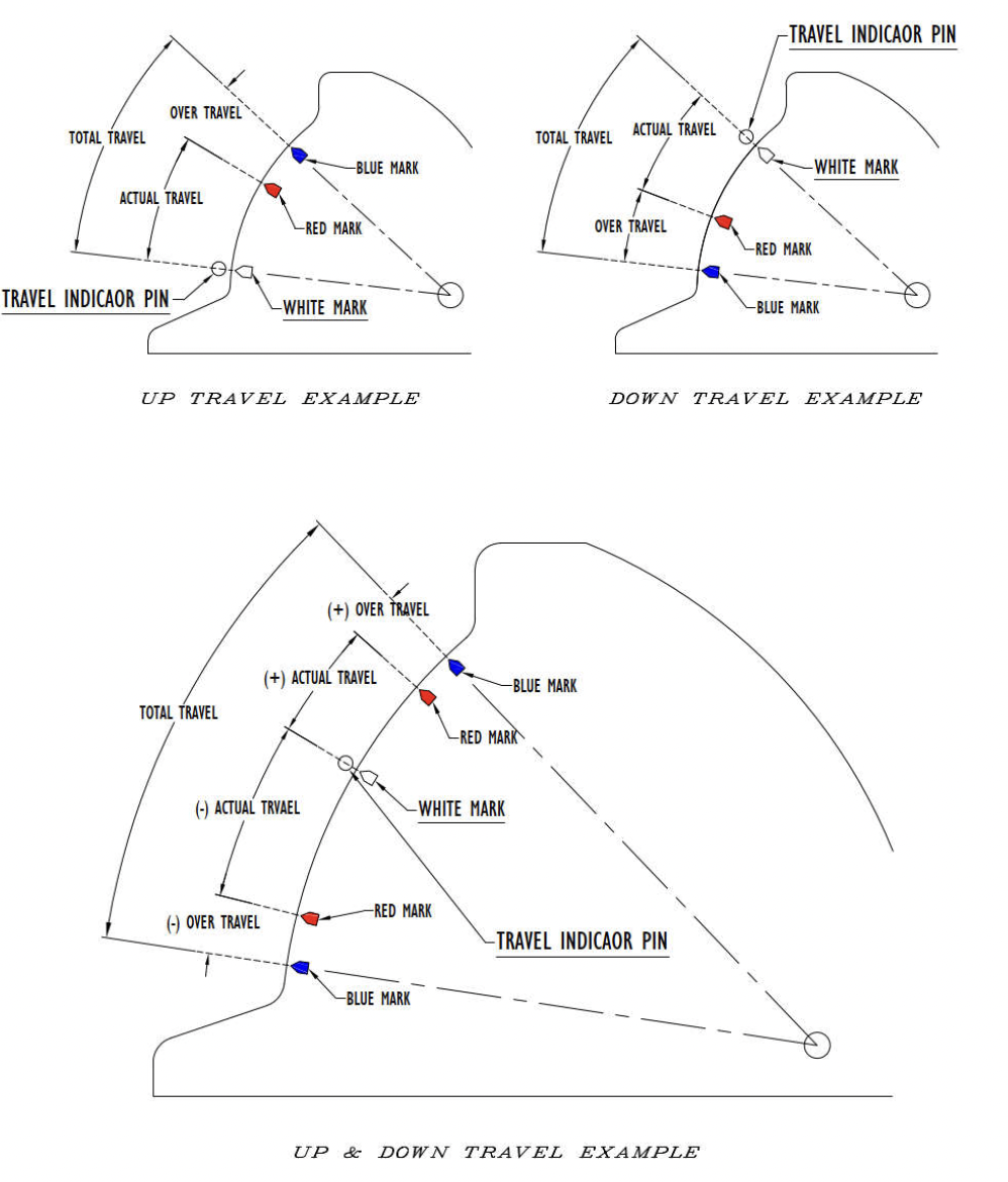
Figure 2: F-type Constants Travel Markings
3) Base type constants: 100-U & 200-U.
Figure 3 below shows a view of travel indicator markings found on above constant support types.
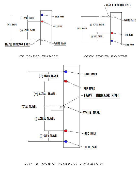
Figure 3: U-type Constants Travel Markings
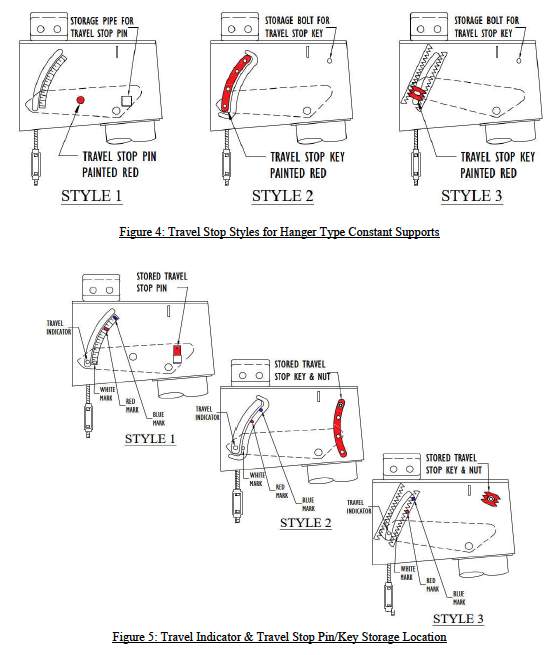
Travel Stop Styles:
Caution: Do not disengage travel stops from their position by force. Forcing the travel stops could cause serious bodily injury, and/or serious damage to the support.
In most cases, travel stops with styles 1, 2, or 3 (figure 4) are removed by hand or light tapping once balance is achieved between the constant support and the entity (piping, vessel, etc) it is supporting. Figure 5 shows examples of the travel stops storage location. May vary with different support types.
– Installing types 100-A, 100-B, 100-C, 100-D, 100-E, 200-A, 200-B, 200-C, 200-D, 200-E:
1. Secure the hanger to a structure capable of handling the operating load, at a point where the constant’s load coupling (turnbuckle) is directly over the desired point of attachment to the pipe in the operating position.
2. The hanger rod and loading arm of the constant should be unobstructed and free to move.
3. Attach the connecting rod to the load coupling (turnbuckle) with full thread engagement.
4. Transfer the load in preparation for Hydro testing and/or commissioning, by turning on the load coupling (turnbuckle) in such a way that will draw the upper and lower rods together to eliminate all slack in the assembly.
5. Hydro testing (if required), with travel stops engaged, should be done at this time, before going to step 6.
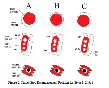
6. The travel stop (painted red) should now be removed once any hydrotesting is completed. The travel stop pin/key shall be in position “B” in figure 6 before it can be removed. Referring to figure 6, unscrew the left & right side nuts by one turn (if equipped). Looking closely, if the pin/key is as in position “A”, rotate the load coupling (turnbuckle) such that to draw the rods together to get to position “B”. If the pin/key is as in position “C”, rotate the load coupling (turnbuckle) such that to separate the rods from each other to get to position “B”. Once disengaged (position “B”), the travel stop/s may be removed and stored in its/their designated location on the constant’s frame (figures 4 & 5).
7. The hanger travel indicator should now be readjusted to the cold position (white mark) shown in figure 1, using the load coupling (turnbuckle) one last time.
8. When the operating conditions are reached, check the hanger to ensure the hanger travel indicator is at or near the hot (red mark) position shown in figure 1. If not, contact the piping designer for further analyses/review of the system.
9. If desired, adjustment can be made by turning the load coupling (turnbuckle) to align the indicator to the hot (red mark) position. This support should be noted for further analyses.
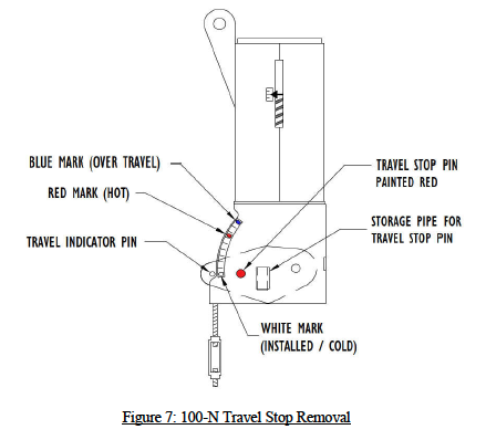
– Installing types 100-N:
1. Secure the hanger to a structure capable of handling the operating load, at a point where the constant’s load coupling (turnbuckle) is directly over the desired point of attachment to the pipe in the operating position.
2. The hanger rod and loading arm of the constant should be unobstructed and free to move.
3. Attach the connecting rod to the load coupling (turnbuckle) with full thread engagement.
4. Transfer the load in preparation for Hydro testing and/or commissioning, by turning on the load coupling (turnbuckle) in such a way that will draw the upper and lower rods together to eliminate all slack in the assembly.
5. Hydro testing should be done at this time, if required, before going to step 6.
6. The travel stop (painted red) should now be removed. Referring to figure 6 on page 5, if the pin is as in position “A”, rotate the load coupling (turnbuckle) such that to draw the rods together to get to position “B”. If the pin is as in position “C”, rotate the load coupling (turnbuckle) such that to separate the rods from each other to get to position “B”. Once disengaged (position “B”), the travel stop may be removed and stored in its storage pipe on the side of the frame (figure 7 ).
7. The hanger travel indicator should now be readjusted to the cold position (white mark) shown in figure 1 (page 1), using the load coupling (turnbuckle) one last time.
8. When the operating conditions are reached, check the hanger to ensure the hanger travel indicator is at or near the hot (red mark) position shown in figure 1 (page 1). If not, contact the piping designer for further analyses/review of the system.
9. If desired, adjustment can be made by turning the load coupling (turnbuckle) to align the indicator to the hot (red mark) position. This support should be noted for further analyses.
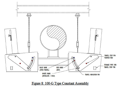
– Installing type 100-G:
1. Support the pipe at the desired elevation.
2. Attach the load rods to a structure capable of handling the operating load, and at the C-C dimension the constant assembly is designed for.
3. The load rod and loading arm of the constant should be unobstructed and free to move.
4. Attach the constant assembly to the load rods using the load coupling (turnbuckle) with full thread engagement.
5. Using the load couplings (turnbuckles), level the pair of channels connecting the two constants. These channels should now be under the piping being supported.
6. Keeping the channels leveled, transfer the load in preparation for Hydro testing and/or commissioning, by turning on each of the load coupling (turnbuckle) in such a way that will draw the upper and lower rods together to eliminate all slack in the assembly.
7. Hydro testing should be done at this time, if required, before going to step 8.
8. The travel stop (painted red) should now be removed. Unscrew the nuts by one turn (if equipped). Referring to figure 6 (page 5), if the pin/key is as in position “A”, rotate the load coupling (turnbuckle) such that to draw the rods together to get to position “B”. If the pin/key is as in position “C”, rotate the load coupling (turnbuckle) such that to separate the rods from each other to get to position “B”. Once disengaged (position “B”), the travel stop/s may be removed and stored in its/their designated location on the constant’s frame (figures 4 & 5 on page 4).
9. The hanger travel indicator should now be readjusted to the cold position (white mark) shown in figure 1, using the load coupling (turnbuckle) one last time.
10. When the operating conditions are reached, check the hanger to ensure the hanger travel indicator is at or near the hot (red mark) position shown in figure 1 (page 1). If not, contact the piping designer for further analyses/review of the system.
11. If desired, adjustment can be made by turning the load coupling (turnbuckle) to align the indicator to the hot (red mark) position. This support should be noted for further analyses. Figure 8:
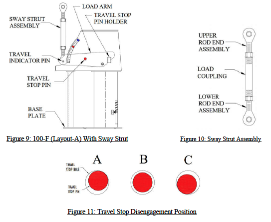
-Installing types 100-F (layout-A):
1. Secure the constant’s base plate to the structure.
2. Attach a load coupling (sway strut) to the piping, then to the constant’s load arm (figure 9).
3. Transfer the load in preparation for Hydro testing and/or commissioning, by turning on the load coupling (sway strut pipe) in such a way that will expand the upper and lower rod end assemblies to eliminate all slack in the assembly. 4. Hydro testing should be done at this time, if required, before going to step 5.
5. The travel stop pin (painted red) should now be removed. Referring to figure 11 below. If the pin is as in position “A”, rotate the sway strut load coupling such that to separate the rod end assemblies from each other (see figure 10) to get to position “B”. If the pin is as in position “C”, rotate the sway strut load coupling such that to draw in the rod end assemblies together to get to position “B”. Once disengaged (position “B”), the travel stop pin may be removed and stored in the travel stop holder on the constant’s frame.
6. The travel indicator should now be realigned with the cold position (white mark) shown in figure 2 on page 2, using the sway strut load coupling one last time.
7. When the operating conditions are reached, check the support to ensure the travel indicator pin is at or near the hot (red mark) position. If not, contact the piping designer for further analyses/review of the system.
8. If desired, adjustment can be made by turning the load coupling (sway strut pipe) to align the indicator to the hot (red mark) position. This support should be noted for further analyses.
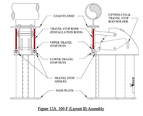
-Installing type 100-F (layout-B) and 200-F (without hydro test blocks):
Note: Installation drawings below are shown for 100-F (layout-B). Type 200-F has the same installation procedure except that the coil housing is in the horizontal position.
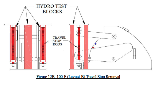
1. Attach the base plate of the constant to the supporting structure by placing the constant in its installation location. If the clearance is tight, temporarily force the load flange down (using the travel stop nuts installed on the all-threaded rod painted red) by loosening the 2 upper travel stop nuts, then tightening the 2 lower travel stop nuts (3/8” max) (figure 12A). Then move the constant into installation location.
2. Loosen the 2 lower travel stop nuts to allow the load flange to rise up to the installed height: 3/8″ max. If the clearance is bigger than 3/8″, shim or grout the constant or pipe attachment accordingly. Tighten the 2 upper and 2 lower travel stop nuts to the travel stop angles in preparation for the hydro testing.
3. Hydro testing should be done at this time, if required.
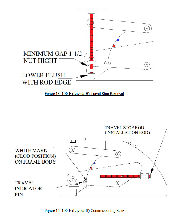
4. The travel stop rods (painted red) should now be removed. Refer to figure 13 on page 11. Back down the 2 lower travel stop nuts flush to the bottom or the travel stop rods. Back up the 2 upper travel-stop nuts at least 1-1/2 times the nut thickness.
5. Unscrew the travel stop rods from the load flange by rotating the rods clockwise until completely removed. Store rods in their designated location on the constant’s frame (see figure 14 on page 11).
6. If the travel indicator pin on the load arm does not line up with the white mark, as in figure 3, when it should, contact the piping designer for further analyses/review of the system.
7. The constant effort support is now ready for commissioning and operation activity.
-Installing type 100-F (layout-B) and 200-F (with hydro test blocks):
Note: Installation drawings below are shown for 100-F (layout-B). Type 200-F has the same installation procedure except that the coil housing is in the horizontal position.
1. Attach the base plate of the constant to the supporting structure by placing the constant in its installation location. If the clearance is tight, temporarily force the load flange down (using the travel stop nuts installed on the all-threaded rod painted red) by loosening the 2 upper travel stop nuts, then tightening the 2 lower travel stop nuts (3/8” max) (figure 12A on page 9). If the hydro test blocks are preventing the load flange from moving down, temporarily remove the hydro test blocks by grinding-off the tack welds that holds them in place, and sliding them out (figure 12B). Then move the constant into installation location.
2. If hydro testing will be performed before commissioning the constant, re-insert the hydro test blocks in their original place after grinding the block as necessary to fit, and tack weld (figure 12B).
3. Loosen the 2 lower travel stop nuts to allow the load flange to rise up to the installed height: 3/8″ max. If the clearance is bigger than 3/8″, shim or grout the constant or pipe attachment accordingly. Tighten the 2 upper and 2 lower travel stop nuts to the travel stop angles in preparation for the hydro testing.
4. Hydro testing should be done at this time, if required, with the hydro test blocks inserted.
5. The hydro test blocks along with the travel stop rods (painted red) should now be removed. Remove the hydro test blocks by grinding-off the tack weld holding them and sliding them out. Refer to figure 13 on page11, to remove the travel stop rods. Back down the 2 lower travel stop nuts flush to the bottom or the travel stop rods. Back up the 2 upper travel stop nuts at least 1-1/2 times the nut thickness.
6. Unscrew the travel stop rods from the load flange by rotating the rods clockwise until completely removed. Store rods in their designated location on the constant’s frame (see figure 14 on page 11).
7. If the travel indicator pin on the load arm does not line up with the white mark, as in figure 3, when it should, contact the piping designer for further analyses/review of the system.
8. The constant effort support is now ready for commissioning and operation activity.
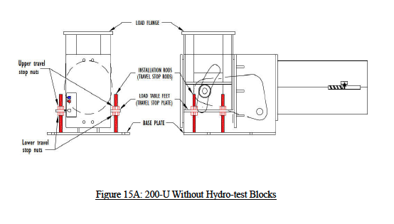
-Installing type 100-U and 200-U (without hydro test blocks):
Note: Installation drawing below (figure 15A) is shown for 200-U. Type 100-U has the same installation procedure except that the coil housing is in the vertical position.
1. Attach the base plate of the constant to the supporting structure by placing the constant in its installation location. If the clearance is tight, temporarily force the load flange down using the travel stop nuts installed on the all-threaded rod (painted red), by loosening the 4 lower travel stop nuts, then tightening the 4 upper travel stop nuts (1/4” max).
2. Move the constant into its installation location.
3. Loosen the 4 upper travel stop nuts to allow the load flange to rise up to the installed height. If the clearance is bigger than 1/4″, shim or grout the constant or pipe attachment accordingly.
4. Tighten the 4 upper and 4 lower travel stop nuts onto the travel stop plate (load table feet) in preparation for the hydro testing.
5. Hydro testing should be done at this time, if required.
6. Back up the 4 upper travel-stop nuts all the way up flush with the top of the installation rods.
7. Back down the 4 lower travel-stop nuts all the way down.
8. If the white marks on load flange feet and travel scale do no remain lined up after line has reached its commissioning statues, contact the piping designer for further analyses/review of the system.
9. The constant effort support is now ready for commissioning and operation activity. Figure 15A:
-Installing type 100-U and 200-U (with hydro test blocks):
Note: Installation drawing below (figure 15B) is shown for 200-U. Type 100-U has the same installation procedure except that the coil housing is in the vertical position.
1. Attach the base plate of the constant to the supporting structure by placing the constant in its installation location. If the clearance is tight, temporarily force the load flange down using the travel stop nuts installed on the all-threaded rod (painted red), by loosening the 4 lower travel stop nuts, then tightening the 4 upper travel stop nuts (1/4” max). If the hydro test blocks are preventing the load flange from moving down, temporarily remove the hydro test blocks by grinding-off the tack welds that holds them in place, then sliding them out. Continue to lower the load flange as needed.
2. Move the constant into its installation location.
3. Loosen the 4 upper travel stop nuts to allow the load flange to rise up to the installed height. If the clearance is bigger than 1/4″, shim or grout the constant or pipe attachment accordingly.
4. If hydro testing will be performed before commissioning the constant, re-insert the hydro test blocks in their original place after grinding the block as necessary to fit; then tack weld.
5. Do not tighten the 4 lower travel stop nuts. This is to allow the hydro test blocks take the load. If tightened, damage to the rods and/or the load table feet may occur.
6. Hydro testing should be done at this time.
7. Remove the hydro test blocks.
8. Back up the 4 upper travel-stop nuts all the way up flush with the top of the installation rods.
9. Back down the 4 lower travel-stop nuts all the way down.
10. If the white marks on load flange feet and travel scale do no remain lined up after line has reached its commissioning statues, contact the piping designer for further analyses/review of the system.
11. The constant effort support is now ready for commissioning and operation activity.
Inspection & Maintenance Procedure
After installation and hydro testing, but before commissioning:
Look for tools, straps, construction debris, and temporary supports that have been left behind which can impair operations of the support by obstruction.
After maintenance and before commissioning:
Look for tools, straps, construction debris, and temporary supports that have been left behind which can impair operations of the support by obstruction.
Periodic inspection and maintenance:
Depending on the environment in which the constant effort support is installed, a biyearly, quarterly, or monthly visual inspection is advised. Monthly to quarterly inspection is highly recommended for supports in windy, sandy, dusty, and salty environments.
Inspection should be done for the following:
- The presence of debris and foreign objects, such as sand, heavy dust, and bird nests that could hamper the support operation movement from cold to hot or hot to cold.
- That the position of the travel indicator located on the load flange feet, is lined up with the red mark anticipated in the design (during operations), or lined up with the white mark (during shutdown). If this is not the case, the piping designer should be notified
- The presence of physical deformation in the support.
Piping Technology & Products constant effort supports use self-lubricating rollers and bearing, that do not require any periodic lubrication.
Essential Piping Support Adjustments and Calibration
Caution: Under no circumstances should an attempt be made to remove the lock nut and the load adjustment nut, in sketch 1 on next page, from the constant spring support as this will result in a serious physical injury.
Every constant spring support is calibrated in the factory and set to the load specified on the nameplate. Load adjustment in the field is discouraged as it may significantly change the system.
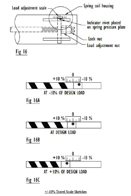
However, to provide for situations where it is desired to increase or decrease the constant’s design load, the constant spring supports are equipped with load adjustment capability. The load adjustment capability consists of a load adjustment scale and indicator which are used to increase (Figure 10A) or decrease (Figure 10C), the load by 10%. Thus, a 2000-pound support can be adjusted for loads from 1800 to 2200 pounds. The travel stop nuts must be engaged before an accurate load adjustment procedure can be performed. Adjusting the load to higher or lower load from the load specified on the nameplate, using the load adjustment scale, is approximate.
Note: Misalignment from the cold set at installation time does not indicate load increase or decrease in the supported system. It indicates further analyses/review is required
Note: The +/-10% in the side of the coil housing is meaningful when the support is at the cold position and locked. Once the travel stop is disengaged (pin removed, nuts backed off), this indicator should be ignored. It will be moving away from the Zero mark as the load arm moves up and down. In many cases it will go out of its load adjustment scale. The constant support is still at its designed load.
The +/-10% Travel Scale
The length from the Zero mark to the +10% or -10% (figure 16) varies based on the coils being used in the support. In general it varies from 1/4” to 1-1/2” starting at the Zero mark.
If smaller load % change is desired, the distance from the Zero mark to the +10% or -10% must be divided accordingly.
Formula: new load % * Distance (from Zero) / 10%
Examples:
Distance from Zero to 10% is 3/4”. To get -5%: -5 * 0.75” / 10 = -0.375” (back up the load adjustment nut 0.375”) To get +3%: 3 * 0.75” / 10 = +0.225” (compress the load adjustment nut 0.225”)
Distance from Zero to 10% is 1/2”. To get -5%: -5 * 0.5” / 10 = -0.25” (back up the load adjustment nut 0.25”) To get +3%: 3 * 0.5” / 10 = +0.15” (compress the load adjustment nut 0.15”)
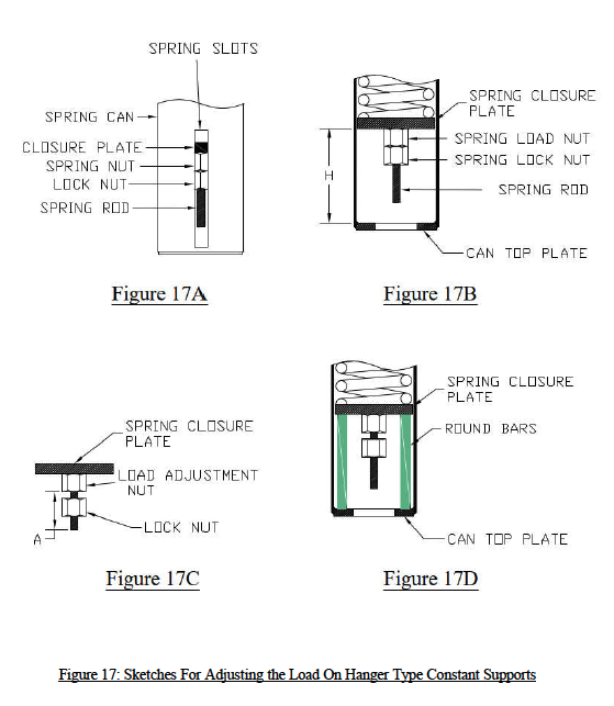
Pre-Installation Checks for Your Support Hanger
See figure 17A for an overall description of the back part of the spring coil housing.
While the red travel stop pin is NOT in place:
Pull or release the load on the hanger rod to place the cam half way within its travel slot. Most of the time, the travel slot is bigger than the total travel. If the travel slot does not exist, then set the cam midway. Hold that position in place.
1. Measure the distance between the inner face of the can’s top plate and the outer face of the spring’s closure plate; marked “H” in figure 17B.
2. Cut 2 round bars having “H” length, with a diameter equaling the spring rod diameter.
3. Backup the lock nut from the load adjustment nut located on the spring rod. Measure the distance between the edge of the spring rod and the outer surface of the load adjustment nut, marked “A” in figure 17C.
4. Pull some more on the hanger rod downward to pull in the closure plate, until you are able to slide in the 2 round bars cut earlier in step # 2. Make sure that they are placed opposite to each other between the can top plate and spring closure plates (see figure 17D).
5. Release the load on the hanger rod slowly until the round bars take the entire load from the spring. You should be able to shake the spring rod with some force at this time.
6. If load is being added, pull up some more on the hanger rod to push out the spring rod and its nut. Gap between the nut and the closure plate should be at least the nut movement or bigger.
7. Turn the nut clockwise to add load (A + nut movement), or counter clockwise to decrease load (A – nut movement). Nut movement is based on the 10% tag attached to the spring can.
8. Tighten the locking nut while holding the load adjustment nut in place.
9. Pull on the hanger rod again until you are able to release and remove the 2 round bars inserted earlier in step # 4. Expect less/more movement from the hanger rod since the spring nut has been moved (the constant is now loaded).
10. Rotate the turnbuckle to move the travel indicator pin to the desired height.
Load Adjustment Procedure For Base Type Restricted End Spring Can
Note: Load adjustment drawing (figure 18E on page 20) is shown for type 200-F. Type 100-F has the same load adjustment procedure except that the coil housing is in the vertical position.
See figure 18A (page 20) for an overall description of the back part of the spring coil can. Position the load flange roughly halfway within its total travel range (while travel stop rods are not installed). Push it down if it is higher. Allow it to push up if it is lower. Hold that position.
1. Measure the distance between the inner face of the can’s top plate and the outer face of the spring’s closure plate; marked “H” in figure 18B (page 20).
2. Cut 2 round bars having “H” length, with a diameter equaling the spring rod diameter.
3. Backup the lock nut from the load adjustment nut located on the spring rod. Measure the distance between the edge of the spring rod and the outer surface of the load adjustment nut, marked “A” in figure 18C on page 20.
4. Lower the load flange to pull in the closure plate until you are able to slide in the 2 round bars cut earlier in step # 2 (colored green in figure 18D on page 20). Make sure that they are placed opposite to each other between the can top plate and spring closure plates.
5. Raise the load flange by using a strap (or another lifting device), up until you are able to shake the spring rod with some force. Note that the weight to be lifted is the weight of the load flange assembly only. Not the design load.
6. If load is being added, raise the load flange up some more to push out the spring rod and its nuts. Gap between the nut and the closure plate should be at least the nut movement needed or bigger. Nut movement is based on the 10% tag attached to the spring can (explained on pages 15 and 16).
7. Turn the nut clockwise to add load (A + nut movement), or counter clockwise to decrease load (A – nut movement).
8. Tighten the locking nut while holding the load adjustment nut in place.
9. Lower the load flange and remove the strap (or another lifting device).
10. Push the load flange down with force, equaling the new load, until you are able to release and remove the 2 round bars inserted earlier in step # 4. Expect less/more movement from the load flange before you are able to release the round bars inserted because the spring nut has been moved. The constant is now loaded, and can be set to the cold position if desired.

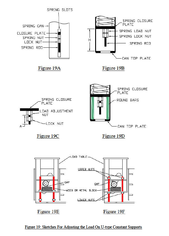
Load Adjustment Procedure for Base Type 100-U & 200-U Restricted End Spring Can
Note: Load adjustment drawings (figure 19E & 19F on page 22) are shown for type 200-U. Type 100-U has the same procedure except that the coil housing is in the vertical position.
See figure 19A (page 22) for an overall description of the back part of the spring coil can.
Position the load table roughly halfway within its total travel range by simultaneously screwing up/down the upper 4 travel stop nuts, then screwing up the lower 4 nuts located on the 4 travel stop rods colored red. Hold that position in place.
1. Measure the distance between the inner face of the can’s top plate and the outer face of the spring’s closure plate; marked “H” in figure 19B (page 22).
2. Cut 2 round bars having “H” length, with a diameter equaling the spring rod diameter.
3. Backup the lock nut from the load adjustment nut located on the spring rod. Measure the distance between the edge of the spring rod and the outer surface of the load adjustment nut, marked “A” in figure 19C (page 22).
4. Lower the 4 bottom nuts, then lower the load table to pull in the closure plate until you are able to slide in the 2 round bars cut earlier in step # 2 (colored green in figure 19D on page 22). Make sure that they are placed opposite to each other between the can top plate and spring closure plates.
5. Raise the table by unscrewing the upper 4 travel stop nuts simultaneously until the inserted round bars take the entire load from the spring. Continue to raise the same nuts all the way to the top of the rod. You should be able to shake the spring rod with some force at this time.
6. Place spacers between the rollers and the load table feet using metal flat bars or wooden blocks (figure 19E on page 22). Minimize the gap between the rollers and spaces as much as possible.
7. Raise the load table some more by screwing up the 4 lower travel stop nuts until the rollers are pushed up about ¼” by the spacers (see figure 19F on page 22).
8. If load is being added, raise the table up some more to push out the spring rod and its nuts. Gap between the nut and the closure plate should be at least the nut movement or bigger. Nut movement is based on the 10% tag attached to the spring can (explained on pages 15 and 16).
9. Turn the nut clockwise to add load (A + nut movement), or counter clockwise to decrease load (A – nut movement).
10. Tighten the locking nut while holding the load adjustment nut in place.
11. Lower the 4 bottom travel stop nuts all the way down to separate the rollers from the spacers. Remove the spacers.
12. Lower the table some more using the 4 upper travel stop nuts, with a force that will equal to the new load, until you are able to release and remove the 2 round bars inserted earlier in step # 4. Expect less/more movement from the table before you are able to release the round bars inserted because the spring nut has been relocated.
13. Finally back up the 4 upper travel stop nuts all the way up to put the constant back in service. The constant is now loaded, and can be set to the cold position if desired.
FAQs
Q: What is the primary function of a constant support?
A: A constant support is designed to provide a consistent, unvarying supporting force throughout its full range of vertical travel. This makes it ideal for piping support systems experiencing significant thermal movement, as it minimizes load transfer to connected equipment and helps maintain system integrity.
Q: How do I know when the spring support is properly adjusted during installation?
A: A spring support is properly adjusted when the position indicator aligns exactly with the specified hot or cold load marks on the travel scale. This confirms that the constant spring is carrying the correct calculated load of the piping system and will perform as intended throughout its range of movement.
Q: When do I remove the travel stops on my support hanger?
A: Travel stops or locking pins must be carefully removed from the support hanger after the piping has been fully installed, hydro-tested, and insulated, but before the system goes into active thermal operation. This ensures the support can properly accommodate thermal movement during service.
Q: How often should a constant spring be inspected?
A: Constant spring supports should be visually inspected during routine plant maintenance or scheduled turnarounds. Inspections should verify that the piping support components are free from excessive corrosion or debris, and that the travel indicator remains within the designed operating range to ensure proper performance.