Download PDF
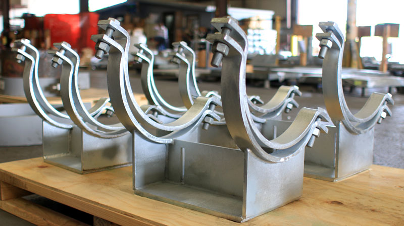
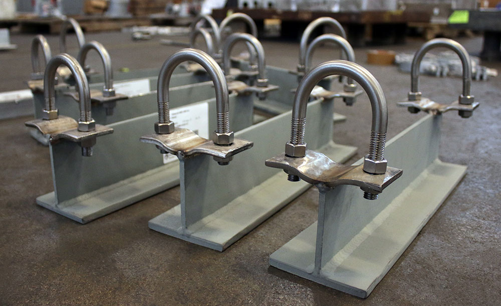
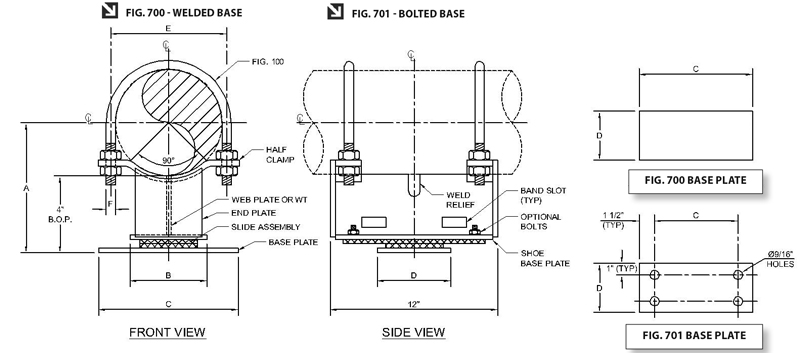
Fig. 700: U-Bolt Cradle Support with Bonded/Bolted Slide Plate
MATERIAL: Carbon steel
FINISH: Painted or hot dipped galvanized.
OPTIONS: Modifications in the dimensions A, B, C, D, and the slide plate material (PTFE, 25% glass filled or graphite) available upon request.
ORDERING: Specify figure number, pipe size, description, type, quantity, finish and slide plate material.
ALLOWABLE LOADS: The allowable vertical loads depend upon the pipe pressure and wall thickness.
BONDING: Graphite slide plates are usually bonded. For high temperature service above 500°F specify bolted construction.
NOTE:
• Optional bolted base plate, specify Fig. 701
• End Plates provided for pipe sizes 3″ & above
• For upper graphite slide material to be of bolted design, specify Fig. 700 base plate or Fig. 701 base plate (see below).
| PIPE SIZE | A | B | C | D | E | F | APPROX. WEIGHT (lb. per each) |
| 2 | 5 3/16 | 4 | 12 | 5 | 2 7/8 | 3/8 | 14.0 |
| 3 | 5 3/4 | 4 | 12 | 5 | 4 1/8 | 1/2 | 14.0 |
| 4 | 6 1/4 | 4 | 12 | 5 | 5 1/8 | 1/2 | 15.0 |
| 6 | 7 5/16 | 4 | 12 | 5 | 7 3/8 | 5/8 | 22.0 |
| 8 | 8 5/16 | 4 | 12 | 5 | 9 3/8 | 5/8 | 25.0 |
| 10 | 9 3/8 | 4 | 12 | 5 | 11 5/8 | 3/4 | 31.0 |
| 12 | 10 3/8 | 4 | 12 | 5 | 13 3/4 | 7/8 | 39.0 |
| 14 | 11 | 4 | 12 | 5 | 15 | 7/8 | 46.0 |
| 16 | 12 | 4 | 12 | 5 | 17 | 7/8 | 49.0 |
| 18 | 13 | 7 | 15 | 5 1/2 | 19 1/8 | 1 | 66.0 |
| 20 | 14 | 7 | 15 | 5 1/2 | 21 1/8 | 1 | 70.0 |
| 24 | 16 | 7 | 15 | 5 1/2 | 25 1/8 | 1 | 78.0 |
Download PDF
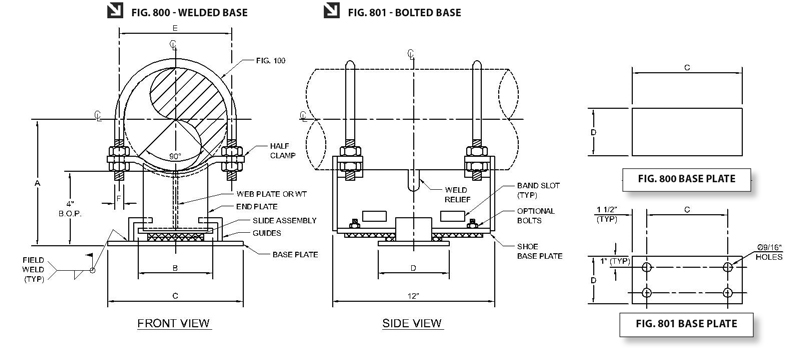
Fig. 800: U-Bolt Cradle Support with Guide & Slide Plate
MATERIAL: Carbon steel
FINISH: Painted or hot dipped galvanized.
OPTIONS: Modifications in the dimensions A, B, C, D, and the slide plate material (PTFE, 25% glass filled or graphite) available upon request.
ORDERING: Specify figure number, pipe size, description, type, quantity, finish and slide plate material.
ALLOWABLE LOADS: The allowable vertical loads depend upon the pipe pressure and wall thickness.
BONDING: Graphite slide plates are usually bonded. For high temperature service above 500°F specify bolted construction.
NOTE:
• Optional bolted base plate, specify Fig. 801.
• For upper graphite slide material to be of bolted design, specify Fig. 800 base plate or Fig. 801 base plate (see below).
| PIPE SIZE | A | B | C | D | E | F | APPROX. WEIGHT (lb. per each) |
| 2 | 5 3/16 | 4 | 7 1/4 | 5 | 2 7/8 | 3/8 | 17.0 |
| 3 | 5 3/4 | 4 | 7 1/4 | 5 | 4/1/8 | 1/2 | 19.0 |
| 4 | 6 1/4 | 4 | 7 1/4 | 5 | 5/18 | 1/2 | 21.0 |
| 6 | 7 5/16 | 4 | 7 1/4 | 5 | 7 3/8 | 5/8 | 24.0 |
| 8 | 8 5/16 | 4 | 7 1/4 | 5 | 9 3/8 | 5/8 | 26.0 |
| 10 | 9 3/8 | 4 | 7 1/4 | 5 | 11 5/8 | 3/4 | 33.0 |
| 12 | 10 3/8 | 4 | 7 1/4 | 5 1/2 | 13 3/4 | 7/8 | 41.0 |
| 14 | 11 | 4 | 7 1/4 | 5 1/2 | 15 | 7/8 | 48.0 |
| 16 | 12 | 4 | 7 1/4 | 5 1/2 | 17 | 7/8 | 51.0 |
| 18 | 13 | 7 | 10 3/4 | 5 1/2 | 19 1/8 | 1 | 72.0 |
| 20 | 14 | 7 | 10 3/4 | 5 1/2 | 21 1/8 | 1 | 76.0 |
| 24 | 16 | 7 | 11 1/4 | 5 1/2 | 25 1/8 | 1 | 86.0 |
Download PDF
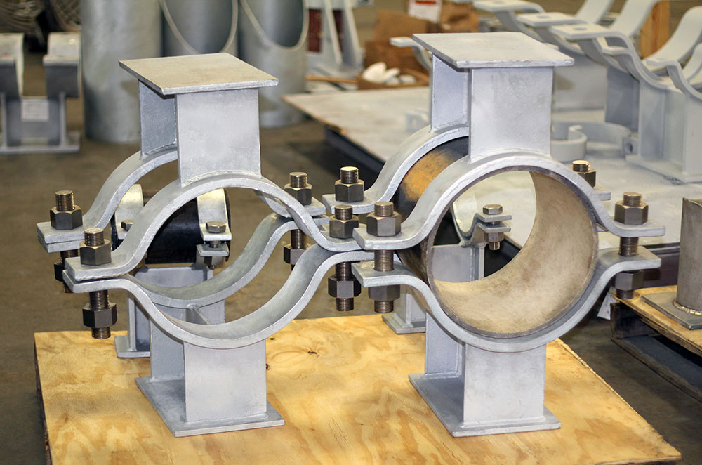
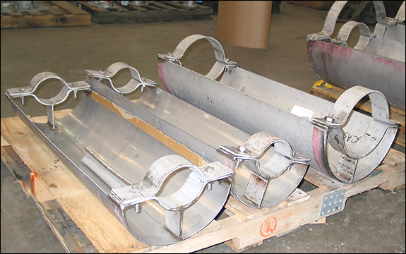
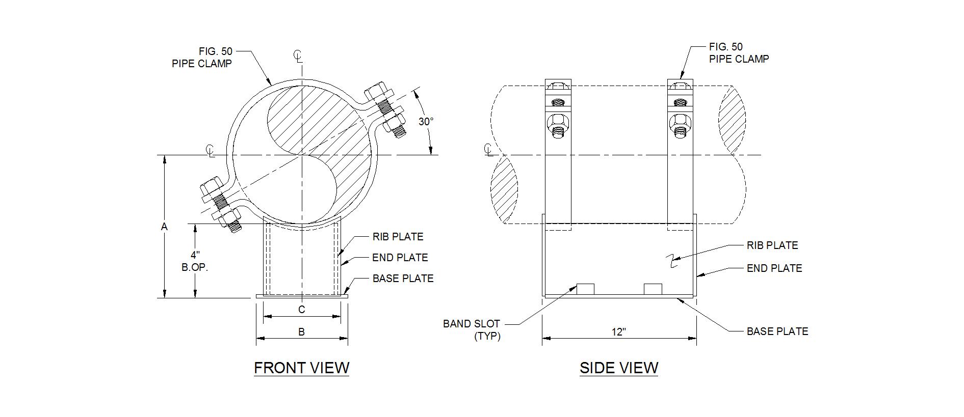
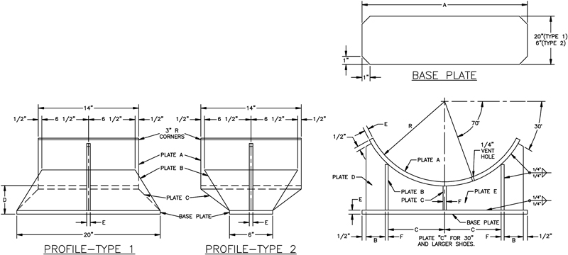
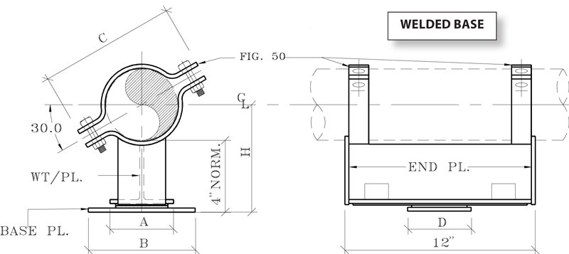
Fig. 900: Bolt Cradle Support with Bonded/Bolted Slide Plate (Welded Base)
MATERIAL: Carbon steel
FINISH: Painted or hot dipped galvanized.
OPTIONS: Modifications in the dimensions A, B, C, D, and the slide plate material (PTFE, 25% glass filled or graphite) available upon request.
ORDERING: Specify figure number, pipe size, description, type, quantity, finish and slide plate material.
ALLOWABLE LOADS: The allowable vertical loads depend upon the pipe pressure and wall thickness.
BONDING: Graphite slide plates are usually bonded. For high temperature service above 500°F specify bolted construction.
NOTE: End Plates provided for pipe sizes 3″ & above
| PIPE SIZE | A | B | C | D | H |
| 2 | 4 | 12 | 5 1/2 | 5 | 5 3/16 |
| 2 1/2 | 4 | 12 | 6 3/8 | 5 | 5 7/16 |
| 3 | 4 | 12 | 7 | 5 | 5 3/4 |
| 4 | 4 | 12 | 8 9/16 | 5 | 6 1/4 |
| 5 | 4 | 12 | 9 11/16 | 5 | 6 13/16 |
| 6 | 4 | 12 | 11 5/8 | 5 | 7 5/16 |
| 8 | 4 | 12 | 13 7/8 | 5 | 8 5/16 |
| 10 | 4 | 12 | 17 | 5 | 9 3/8 |
| 12 | 4 | 12 | 18 15/16 | 5 | 10 3/8 |
| 14 | 4 | 12 | 21 | 5 | 11 |
| 16 | 4 | 12 | 23 | 5 | 12 |
| 18 | 7 | 15 | 25 7/8 | 5 1/2 | 13 |
| 20 | 7 | 15 | 28 | 5 1/2 | 14 |
| 24 | 7 | 15 | 33 1/2 | 5 1/2 | 16 |
Download PDF
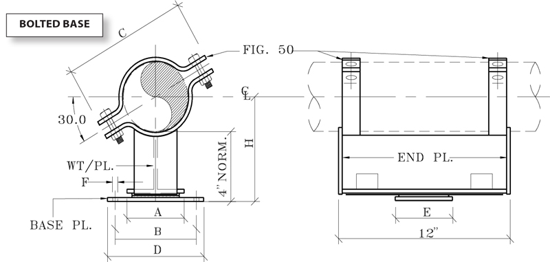
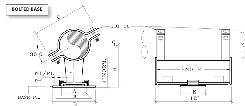
Fig. 1000: Bolt Cradle Support with Bonded/Bolted Slide Plate (Bolted Base)
MATERIAL: Carbon steel
FINISH: Painted or hot dipped galvanized.
OPTIONS: Modifications in the dimensions A, B, C, D, and the slide plate material (PTFE, 25% glass filled or graphite) available upon request.
ORDERING: Specify figure number, pipe size, description, type, quantity, finish and slide plate material.
ALLOWABLE LOADS: The allowable vertical loads depend upon the pipe pressure and wall thickness.
BONDING: Graphite slide plates are usually bonded. For high temperature service above 500°F specify bolted construction.
NOTE: End Plates provided for pipe sizes 3″ & above
| PIPE SIZE | A | B | C | D | E | F | H |
| 2 | 4 | 16 | 5 1/2 | 18 | 5 | 13/16 | 5 3/16 |
| 2 1/2 | 4 | 16 | 6 3/8 | 18 | 5 | 13/16 | 5 7/16 |
| 3 | 4 | 16 | 7 | 18 | 5 | 13/16 | 5 3/4 |
| 4 | 4 | 16 | 8 9/16 | 18 | 5 | 13/16 | 6 1/4 |
| 5 | 4 | 16 | 9 11/16 | 18 | 5 | 13/16 | 6 13/16 |
| 6 | 4 | 16 | 11 5/8 | 18 | 5 | 13/16 | 7 5/16 |
| 8 | 4 | 16 | 13 7/8 | 18 | 5 | 13/16 | 8 5/16 |
| 10 | 4 | 16 | 17 | 18 | 5 | 13/16 | 9 3/8 |
| 12 | 4 | 16 | 18 15/16 | 18 | 5 | 13/16 | 10 3/8 |
| 14 | 4 | 16 | 21 | 18 | 5 | 13/16 | 11 |
| 16 | 4 | 16 | 23 | 18 | 5 | 13/16 | 12 |
| 18 | 7 | 18 1/2 | 25 7/8 | 21 | 5 1/2 | 15/16 | 13 |
| 20 | 7 | 18 1/2 | 28 | 21 | 5 1/2 | 15/16 | 14 |
| 24 | 7 | 18 1/2 | 33 1/2 | 21 | 5 1/2 | 15/16 | 16 |
Download PDF
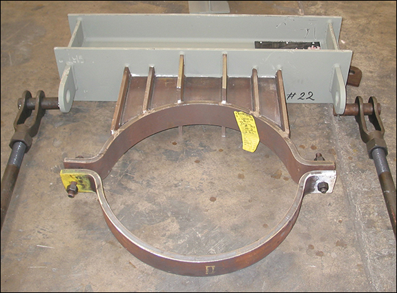
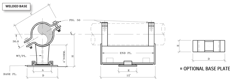
Fig. 1100: Bolt Cradle Support with Guide & Slide Plate (Welded Base)
MATERIAL: Carbon steel
FINISH: Painted or hot dipped galvanized.
OPTIONS: Modifications in the dimensions A, C, D, E, and the slide plate material (PTFE, 25% glass filled or graphite) available upon request.
ORDERING: Specify figure number, pipe size, description, type, quantity, finish and slide plate material.
ALLOWABLE LOADS: The allowable vertical loads depend upon the pipe pressure and wall thickness.
BONDING: Graphite slide plates are usually bonded. For high temperature service above 500 °F specify bolted construction.
PIPE SIZE
| A
| C
| D
| E
| H
|
2
| 4
| 5 1/2
| 7 1/4
| 5
| 5 3/16
|
2 1/2
| 4
| 6 3/8
| 7 1/4
| 5
| 5 7/16
|
3
| 4
| 7
| 7 1/4
| 5
| 5 3/4
|
4
| 4
| 8 9/16
| 7 1/4
| 5
| 6 1/4
|
5
| 4
| 9 11/16
| 7 1/4
| 5
| 6 13/16
|
6
| 4
| 11 5/8
| 7 1/4
| 5
| 7 5/16
|
8
| 4
| 13 7/8
| 7 1/4
| 5
| 8 5/16
|
10
| 4
| 17
| 7 1/4
| 5
| 9 3/8
|
12
| 4
| 18 15/16
| 7 1/4
| 5
| 10 3/8
|
14
| 4
| 21
| 7 1/4
| 5
| 11
|
16
| 4
| 23
| 7 1/4
| 5
| 12
|
18
| 7
| 25 7/8
| 10 3/4
| 5 1/2
| 13
|
20
| 7
| 28
| 10 3/4
| 5 1/2
| 14
|
24
| 7
| 33 1/2
| 11 1/4
| 5 1/2
| 16
|
Download PDF
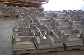
Fig. 1200: Bolt Cradle Support with Guide & Slide Plate (Bolted Base)
MATERIAL: Carbon steel
FINISH: Painted or hot dipped galvanized.
OPTIONS: Modifications in the dimensions A, B, C, D, and the slide plate material (PTFE, 25% glass filled or graphite) available upon request.
ORDERING: Specify figure number, pipe size, description, type, quantity, finish and slide plate material.
ALLOWABLE LOADS: The allowable vertical loads depend upon the pipe pressure and wall thickness.
BONDING: Graphite slide plates are usually bonded. For high temperature service above 500°F specify bolted construction.
| PIPE SIZE | A | B | C | D | E | F | H |
| 2 | 4 | 9 1/4 | 5 1/2 | 11 1/4 | 5 | 13/16 | 5 3/16 |
| 2 1/2 | 4 | 9 1/4 | 6 3/8 | 11 1/4 | 5 | 13/16 | 5 7/16 |
| 3 | 4 | 9 1/4 | 7 | 11 1/4 | 5 | 13/16 | 5 3/4 |
| 4 | 4 | 9 1/4 | 8 9/16 | 11 1/4 | 5 | 13/16 | 6 1/4 |
| 5 | 4 | 9 1/4 | 9 11/16 | 11 1/4 | 5 | 13/16 | 6 13/16 |
| 6 | 4 | 9 1/4 | 11 5/8 | 11 1/4 | 5 | 13/16 | 7 5/16 |
| 8 | 4 | 9 1/4 | 13 7/8 | 11 1/4 | 5 | 13/16 | 8 5/16 |
| 10 | 4 | 9 1/4 | 17 | 11 1/4 | 5 | 13/16 | 9 3/8 |
| 12 | 4 | 9 1/4 | 18 15/16 | 11 1/4 | 5 | 13/16 | 10 3/8 |
| 14 | 4 | 9 1/4 | 21 | 11 1/4 | 5 | 13/16 | 11 |
| 16 | 4 | 9 1/4 | 23 | 11 1/4 | 5 | 13/16 | 12 |
| 18 | 7 | 13 3/4 | 25 7/8 | 16 1/4 | 5 1/2 | 15/16 | 13 |
| 20 | 7 | 13 3/4 | 28 | 16 1/4 | 5 1/2 | 15/16 | 14 |
| 24 | 7 | 14 1/4 | 33 1/2 | 16 1/4 | 5 1/2 | 15/16 | 16 |