
Types & Sizes
Technical Information
Methods of Protecting against Corrosion
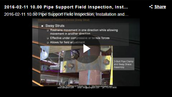
Considering All Movement in Pipe Support Design
Comparative Corrosion Resistance Guide
Case Studies
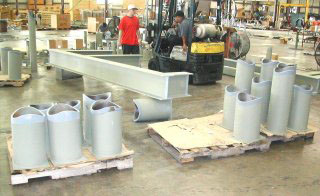
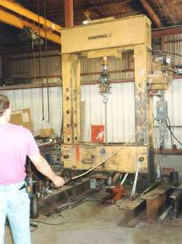
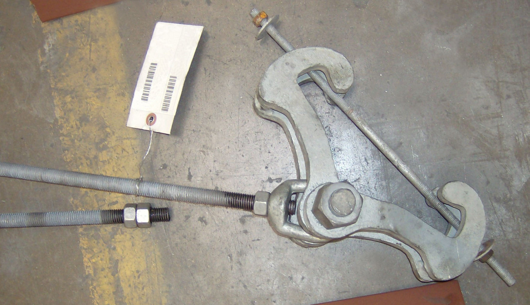
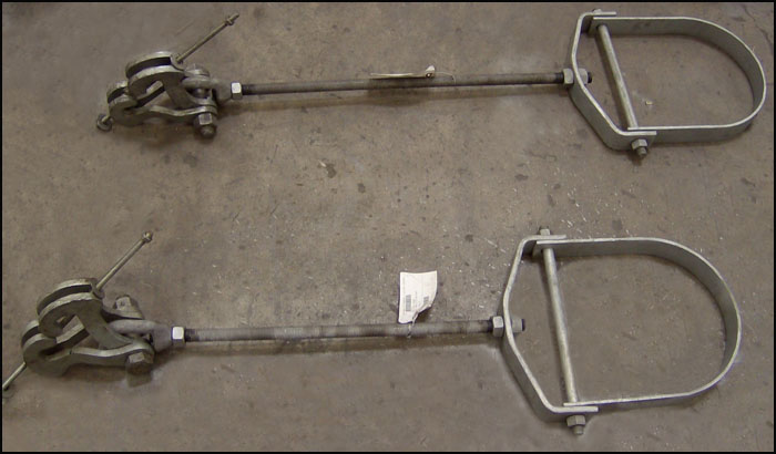
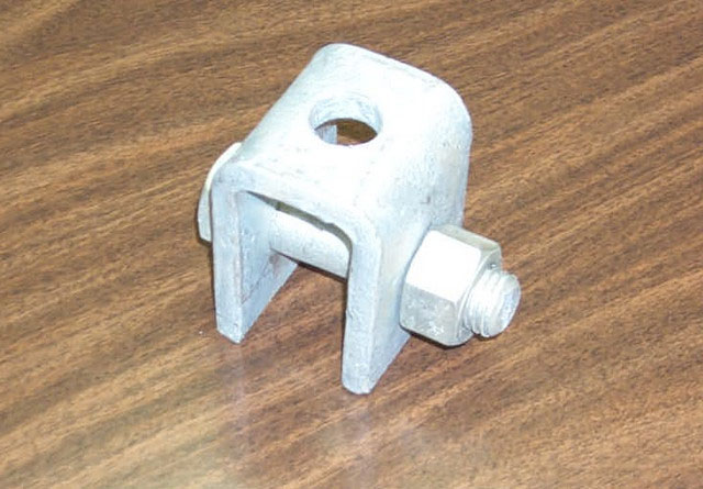
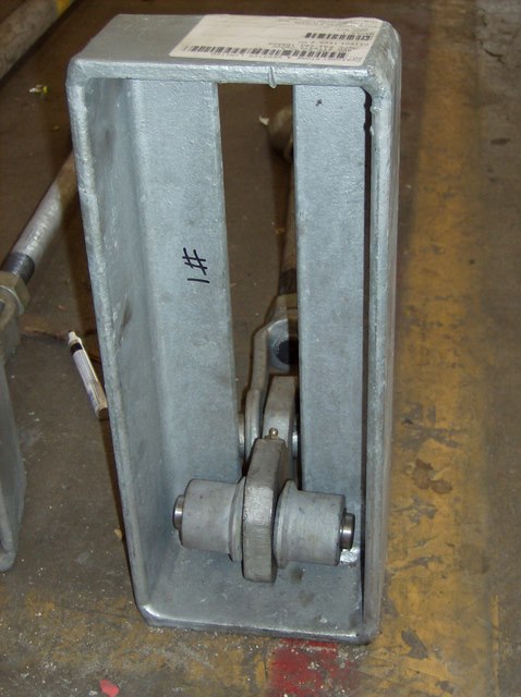
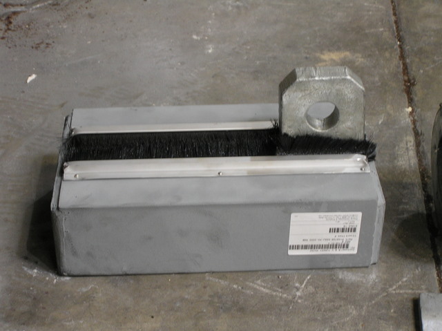
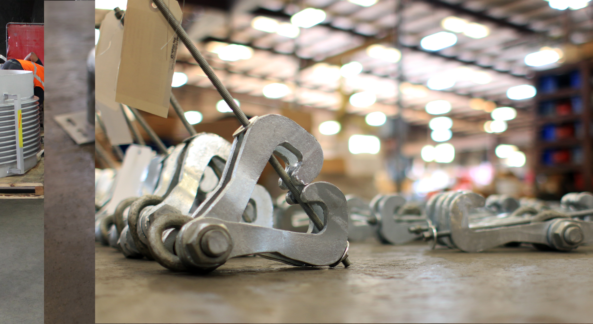
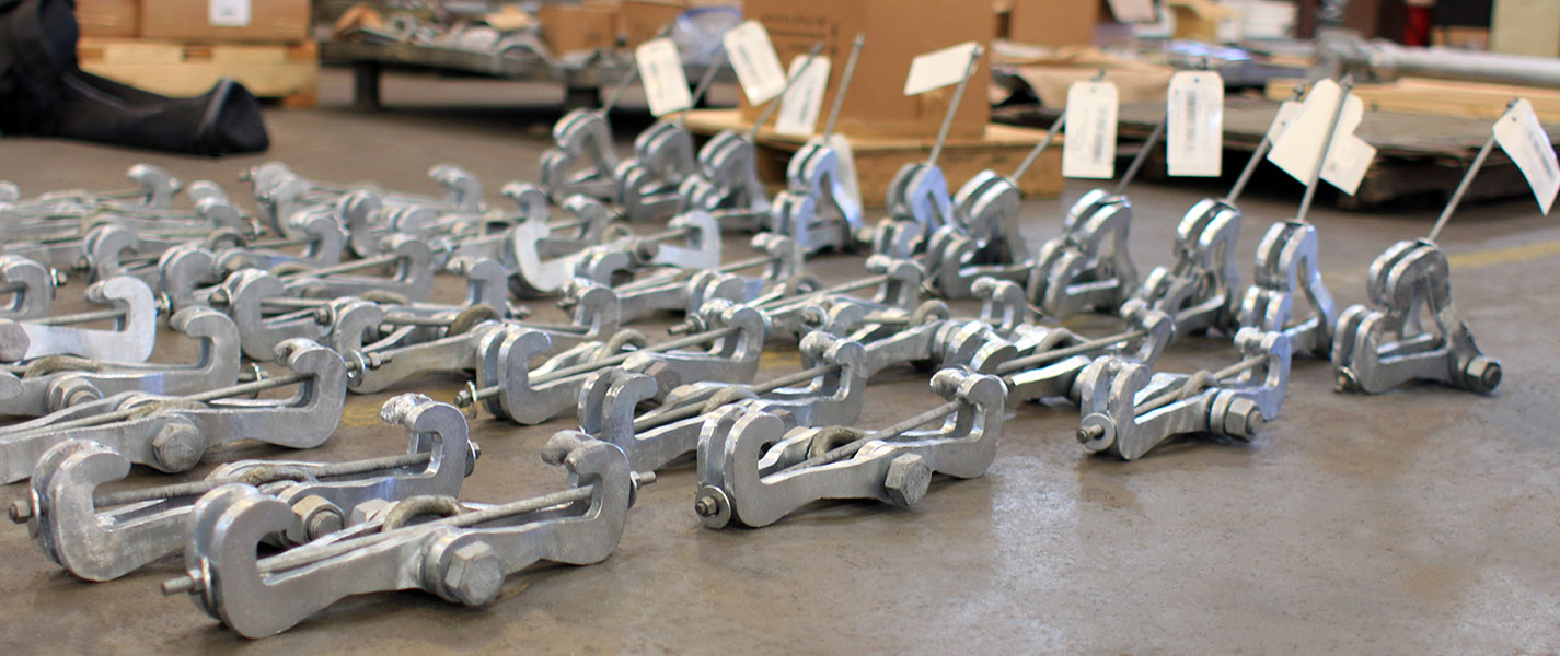
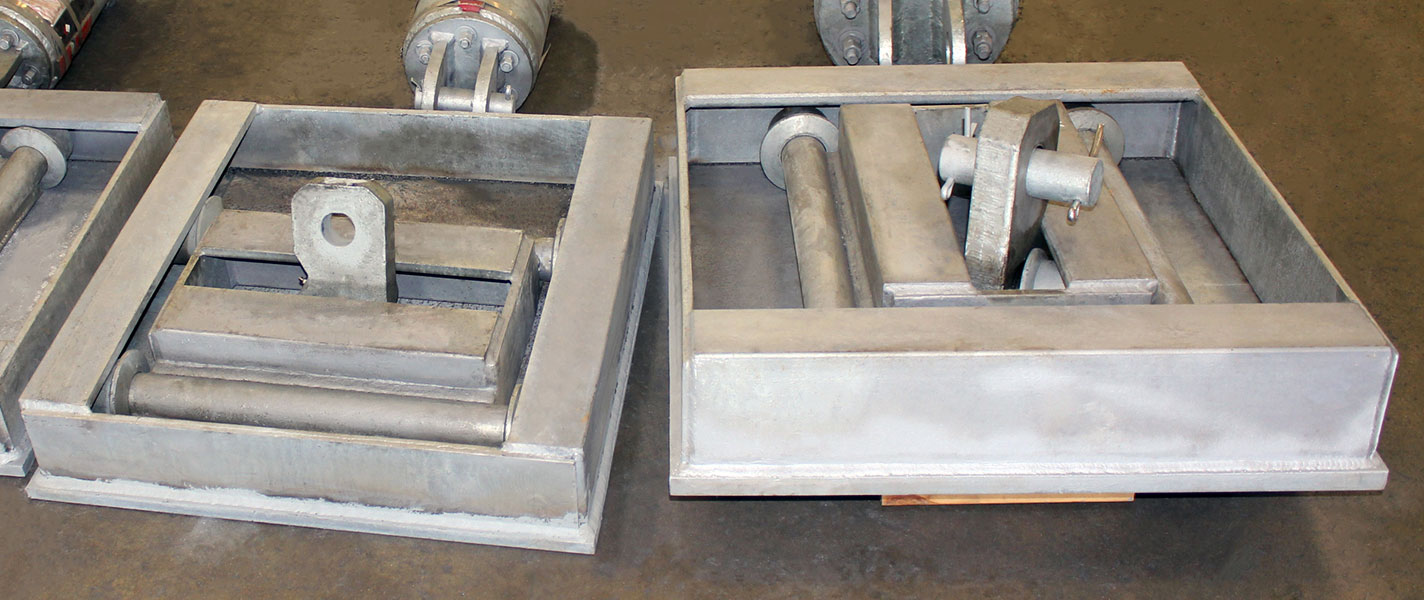
10/17/07: 10″ Beam Clamp Assemblies for an Electric Plant in West Virginia
Request a Quote