This guide details the critical installation and maintenance protocols for variable spring hanger units to ensure long-term system reliability. Functioning as dynamic hanger pipe supports, these devices require precise adjustment of the travel stops and load indicators to accommodate thermal expansion.
We cover the necessary steps to secure the spring anchor attachment to the building structure and provide guidelines for ongoing inspection to prevent lock-up or drift. Whether commissioning a new system or performing routine maintenance on an existing hangar support, following these procedures ensures the piping system maintains flexibility without compromising safety.
There are seven types of variable spring hangers, designated by the letters A-G. These are shown in Figure 1, below. The primary difference between the types is in the manner in which they are supported, and thus, the details of installation will be different for each type. More information on the individual types may be found in our pipe supports catalog or on our products page. During assembly, the coils of the variable springs are pre-compressed to the cold load position, and travel stops are installed.
The travel stops are painted red and held in place with stainless steel shipping bands, as shown in Figure 2. While these are in place, loads applied to the unit, such as hydro-testing loads, will not be transferred to the spring coil. Thus, hydro testing must be done with the stops in place. These stops must be removed during installation while the cold load is on the spring. They are removed by cutting the shipping bands shown in the figure. See a video on how to remove travel stops.
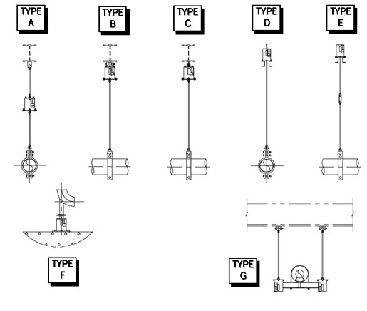
Figure 1: Types of Variable Spring Hangers
Note: All load readings are taken from the bottom of the indicator. This is a pressure plate lug that protrudes from the slots in the can.
Figure 2: Travel Stops for Variable Spring Hangers
Variable Types A, B, C
Each of these is provided with an attachment that connects the top of the spring can to an overhead structural member. Type A is supplied with a threaded bushing for a threaded rod, which in turn is connected to the structural support. Types B and C are provided with one or two lugs, respectively. These are then attached to the structural support. The pipe is then suspended below the spring can using a rod assembly.
1. Securely connect the top attachment to a point on the structure directly above the pipe that the spring is to support. Attach a pipe clamp or other hardware to the bottom end of the rod. Attach the clamp to the pipe. Perform hydro-testing if it is required. Cut the shipping bands off and remove the lower travel stops. The upper travel stops must be removed now. To remove these travel stops, turn the load column or turnbuckle clockwise until the travel stops become loose enough to be removed by hand.
2. After removing the upper travel stops, turn the load column counterclockwise to bring the load indicator back to the cold load mark. Use a lock nut to secure the rod.
Variable Types D and E
These rest on the supporting structural member, usually on a pair of channels. Type D has a rod which passes through the hanger, permitting adjustment from the top.
1. Securely weld or bolt the bottom of the spring to the structure. For Type D, pass the hanger rod assembly through the load column and attach it with a washer and hex nut to hold the hanger rod in position. Attach the clamp to the rod assembly to support the pipe. Perform hydro-testing if it is required. Cut the shipping bands off and remove the lower travel stops. The upper travel stops must be removed now. To remove travel stops, turn the load column or turnbuckle clockwise until travel stops become loose enough to remove by hand.
2. After removing the upper travel stops, turn the load column or turnbuckle counterclockwise to bring the load indicator back to the cold load mark. Use a lock nut to secure the rod.
Type F Spring (Base TYPE)
In Type F springs, the pipe rests on the support, which is typically welded or bolted to the floor or other structural member.
1. Securely attach the spring casing base plate to the supporting structure by bolting or welding the base plate to the structure. Place the load flange on the load column and turn the load column counterclockwise until the load flange is against the pipe. This may be done by inserting a bar into holes in the load column and turning the column as a jack screw. Perform hydro testing if needed. Cut the shipping bands off and remove the lower travel stops. Turn the load column counterclockwise until the upper travel stop loosens enough that it can be removed by hand.
2. After removing the upper travel stop, turn the load column counterclockwise to bring the load indicator back to the cold load mark.
Type G Spring (Double)
The Type G spring consists of two regular springs that support a beam between them. The pipe then rests on the beam.
1. Connect the rod assembly to the load columns. Connect the other end of the rods to the structural support. Make sure the spring cans are suspended with the rod assembly above the spring. Install the pipe on the supports. Perform hydro-testing if it is required. Cut the shipping bands off and remove the lower travel stops. The upper travel stops must be removed now. To remove travel stops, turn the load column or turnbuckle clockwise until travel stops become loose enough.
2. After removing the upper travel stops, turn the load column counterclockwise to bring the load indicator back to the cold load mark.
Adjustment
After a reasonable period of operation, the load indicator should be at “H” on the nameplate. If it is not, the hanger should be readjusted to the hot load position. On Types A, B, C, E, and G, this will normally be done by turning the turnbuckle. On Types D and F, the adjustment involves turning the load column.