Piping Technology & Products, Inc. FEA and Custom Pipe Support Design
Over the 40+ years, no company has done more custom design work on pipe supports than PT&P. We have worked with most major EPCs, as well as numerous operating plants. In fact, we started the business by custom designing a thick-walled expansion joint for Dow Plaquemine. PT&P utilizes ANSYS software for doing FEA and thermal analysis. PT&P has done FEA work with a wide variety of materials, including:
- Carbon Steel
- Stainless Steel
- Super Alloys (Monel 400, Hastelloy, etc.)
- Micarta
- Calcium Silicate
- Foam
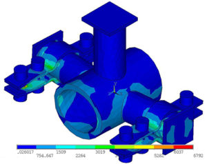
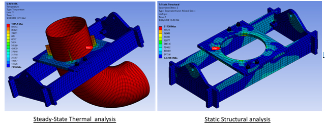
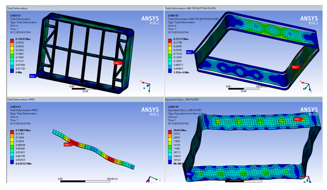
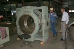
One of the big advantages of PT&P is that not only can we do FEA, we can also manufacture and test our designs even at extreme loads or temperatures. Figure A below shows examples of custom design, FEA Analysis, and testing that has been done by PT&P.
Figure A – Extreme Scenarios of FEA
Our testing capabilities include:
- Continuous Load Testing to 100K lbs
- Impulse load testing to 125K lbs
- Cyclical load testing to 50K lbs
- Cryogenic and high-temperature testing
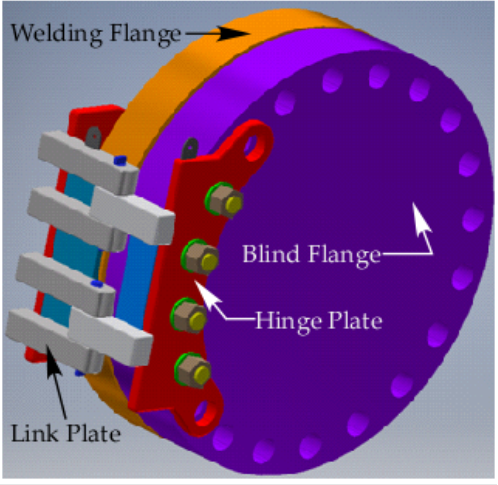
Case Study #1: Closure Flange Hinge Support (CFSH)
PT&P invented the closure flange hinge support (CFSH) for supporting a medium to heavy-duty blind flange. It consists of either a permanent hinge assembly or a removable hinge assembly. These blind flanges are used in ships, tanks, pipelines, heat exchangers, etc. The uniqueness of this invention is the expanded bolting mechanism between hinge assembly and flange that allows swing of the blind flange without the help of a crane or heavy lifting device. It can be used on a wide range of blind flanges of any size as well as customized blind flanges.
Figure 1 – Closure Flange Hinge Support
 |
Product specification:
Type: Permanent |
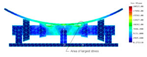
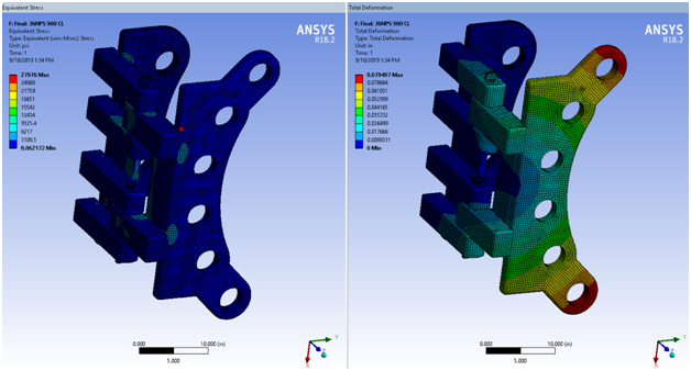
Figure 2 below shows the finite element analysis conducted for this product. In its installation, the product was approved by one of the world’s largest EPCs and hundreds of units were installed in a new plant build.
Figure 2 – Finite Element Analysis for CFSH
Case Study #2: Custom Pipe Clamp
Figure 3 below shows a custom-sized pipe clamp supporting a 47,500 load at 1015°F.
Figure 3 – Custom Pipe Clamp
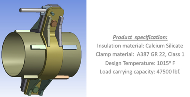
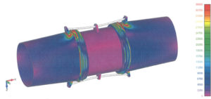
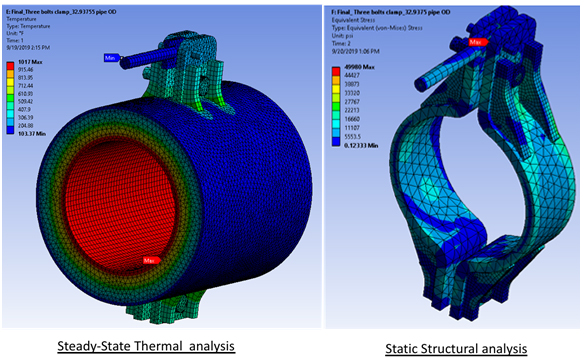
Figure 4 shows the FEA for this pipe clamp.
Figure 4 – FEA for Custom Pipe Clamp
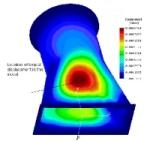
Case Study #3: Custom Riser Clamp for Elbow
In situations where the use of a welded lug attachment would create an undesirable crushing effect on the pipe wall, this clamp can transfer the load from the pipe wall to the riser clamp through hold-down lugs welded to the pipe.
Figure 5 – Custom Riser Clamp for Elbow
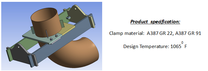
Figure 6 – Custom Riser Clamp for Elbow FEA Analysis
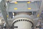
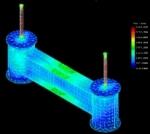
Case Study #4: Custom Rectangular Expansion Joint
PT&P provided a design for a custom universal rectangular joint to be fitted between the steam turbine and its condenser (exhaust). The design conditions were full vacuum at 250°F, 0.43 inches lateral movement. The universal expansion was internally braced (10 in NPS xs pipe, 1-1/2 in wall thickness of the centerline spool). Figure 7 and figure 8 show the design and associated stress analysis.
Figure 7 – Custom Universal Rectangular Expansion Joint
Figure 8 – FEA for Custom Rectangular Expansion Joint
PT&P has extensive in-house finite element analysis capabilities using ProEngineer, ANSYS, and a variety of other software packages.

See this detailed analysis of a transition piece for a sample of our work.