Hardware

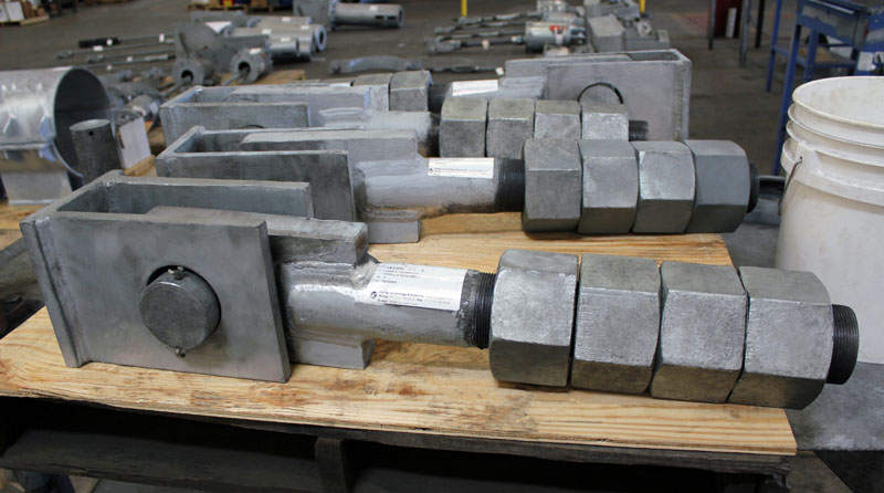
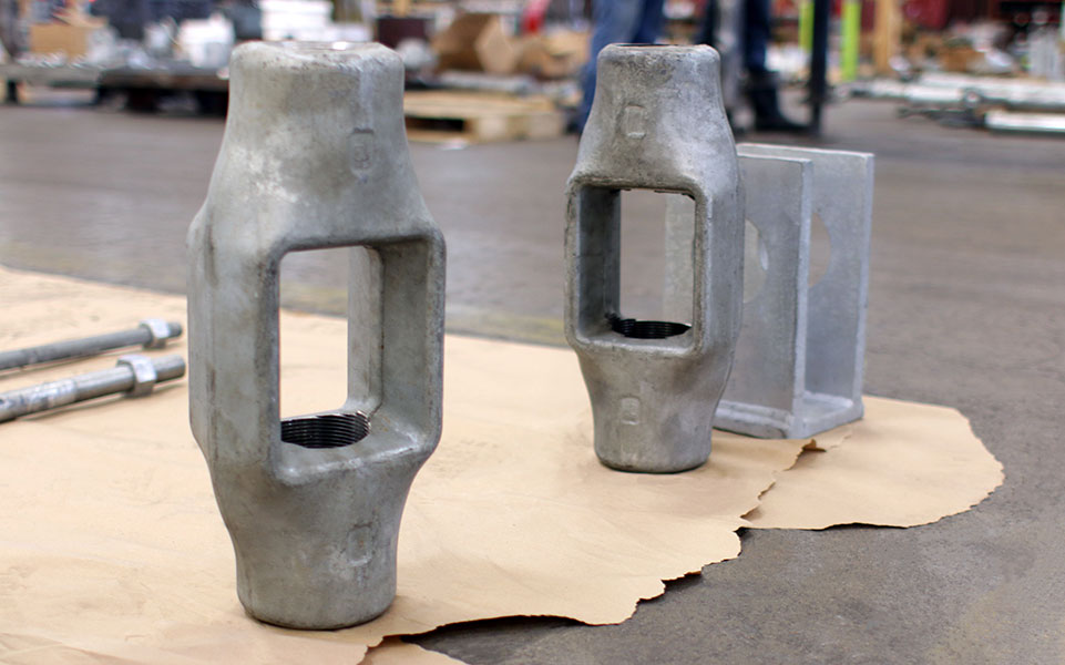
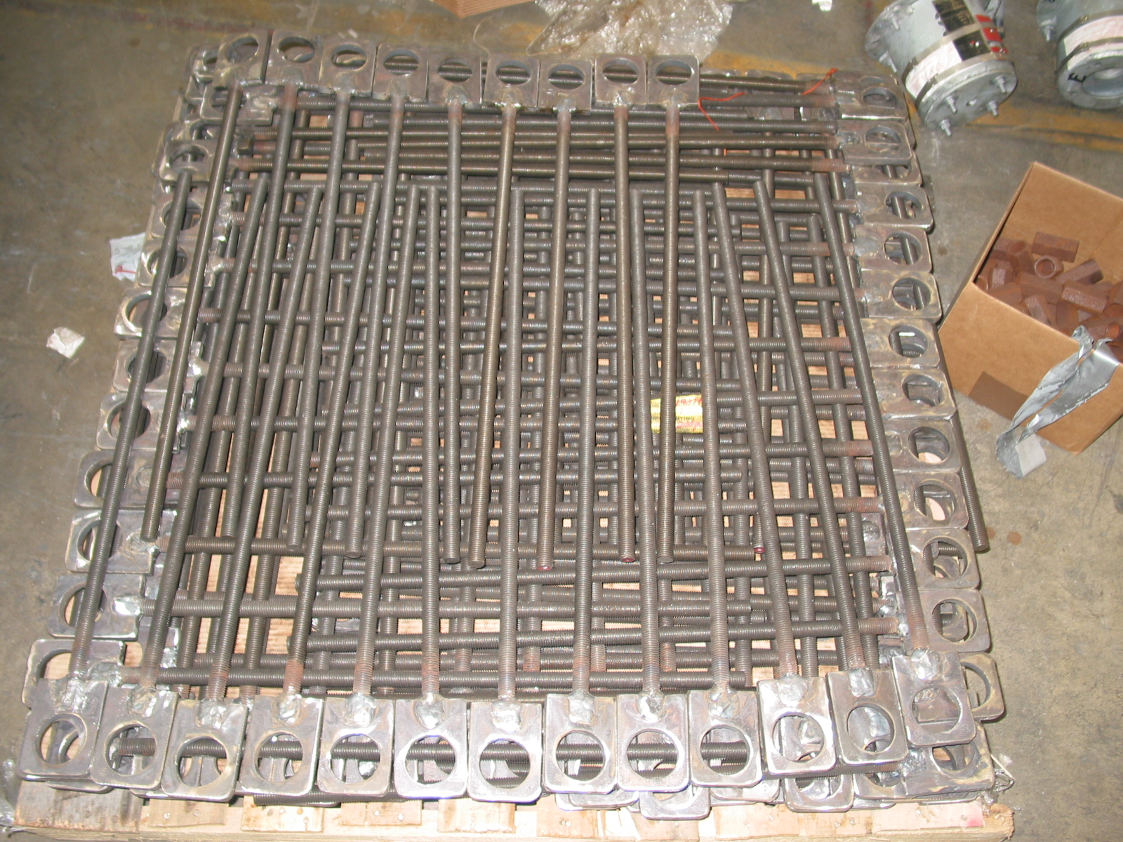
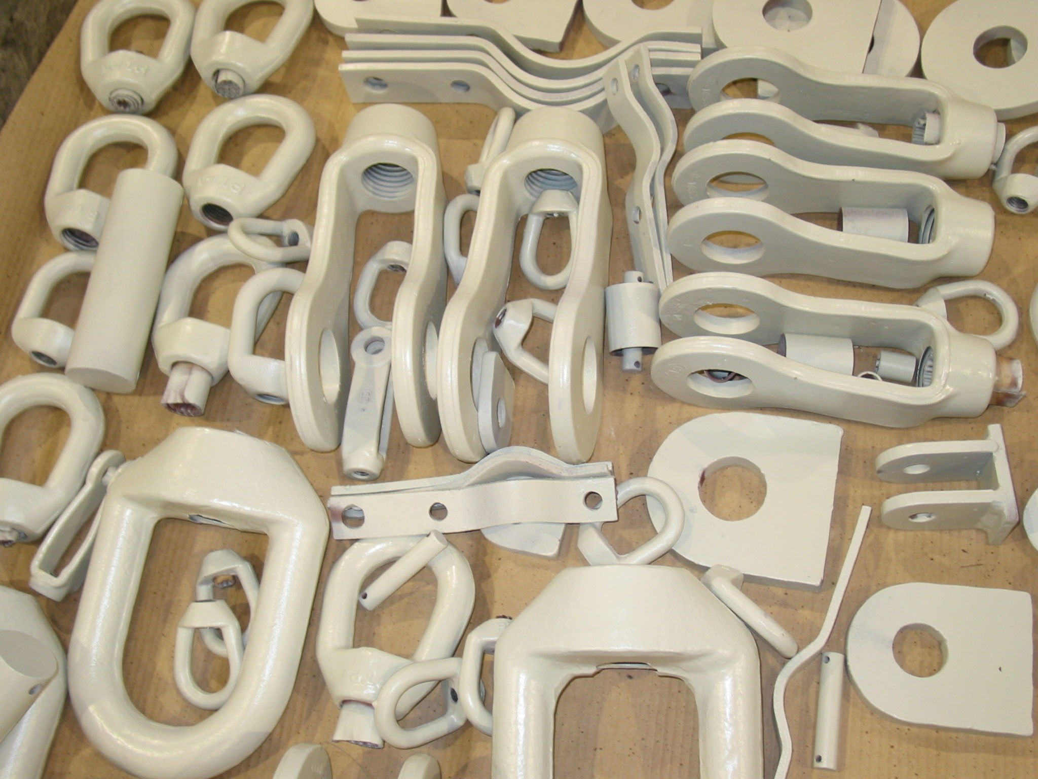
Pipe support hardware is used to assemble a pipe hanger assembly.

Ammonia Plant
Chemical Plant
Clean Fuels
Commercial

Electric Plant
Energy Facility
Ethylene Plant
LLDPE Chemical Plant

LNG Plant
MTBE Plant
Natural Gas Combined Cycle Facility
Natural Gas Processing & Separation

Oil Refinery
Oil Sand Mine
Paper Manufacturer
See All

See More Images

U-bolts can be utilized as pipe guides when the horizontal forces are relatively small (usually 10% or less) compared with ...Continue Reading

Linked eye rods are primarily used in rod hanger assemblies where lateralor axial pipe movement must be accommodated. Linked Eye ...Continue Reading

An eye rod is a hanger rod where the lower section consists of either a formed portion (to form an ...Continue Reading

Long tangent refers to the length of the straight leg portion of the u-bolt which specifies the height of the ...Continue Reading

In order to specify a u-bolt for pipes, you must provide the diameter of the pipe, the material, the tangent ...Continue Reading

When installing clevises, first you should disengage the pin connection of the clevis. Then align the clevis pin holes with ...Continue Reading


More FAQs…

GENERAL DIMENSIONS & SPECIFICATIONS

Download PDF

Fig. 30: Turnbuckle

Fig30Fig30
Fig30


        Fabricated                                                                                                Forged

MATERIAL: Carbon steel
FINISH: Black or galvanized, furnished black unless otherwise specified.
SERVICE: Provides adjustment up to 6” for heavy loads.
ORDERING: Specify figure number, rod size, description and finish. We may supply fabricated or forged.

ROD SIZE

MAX.

RECOM. LOAD (lb.)

S
T

WEIGHT

(lb. per 100)

A
@650° F
@750° F
3/8
730
572
7 1/4
5/8
34
1/2
1350
1057
7 1/2
3/4
47
5/8
2160
1692
7 3/4
7/8
86
3/4
3230
2530
8 1/4
1 1/8
134
7/8
4480
3508
8 1/2
1 1/4
190
1
5900
4620
9
1 1/2
247
1 1/8
7660
5560
9 1/4
1 5/8
338
1 1/4
9500
7440
9 1/4
1 5/8
330
1 1/2
13800
10807
9 3/4
1 7/8
530
1 3/4
18600
14566
10 1/2
2 1/4
780
2
24600
19265
11
2 1/2
1195
2 1/4
32300
25295
12 1/4
3 1/8
2700
2 1/2
39800
31169
12 1/4
3 1/8
2690

Download PDF

Fig. 40: Weldless Eye Nut

Fig40                


MATERIAL: Forged steel
SERVICE: For use on high temperature piping installation.
FEATURES:
 Supports loads equal to the full limitation of the hanger rod.
 Provides flexible connection when used with straight thread rods.

ORDERING: Specify figure number, rod size, description, rod tapping and finish.

SIZE NO.
ROD SIZE A

MAX. RECOM.

LOAD (lbs.)

B
C
D
E
F
G

APPROX.

WEIGHT

(lbs. per 100)

@650°F
@750°F
1
3/8
730
572
1 1/2
1 3/16
1/2
2
1 3/8
11/16
68
1/2
1350
1057
69
5/8
2160
1692
66
3/4
3230
2530
59
2
7/8
4480
3508
2
1 11/16
3/4
2 5/8
1 15/16
1
170
1
5900
4620
170
3
1 1/8
7660
5560
2 1/2
1 13/16
1
3 3/8
2 3/8
1 1/4
380
1 1/4
9500
7440
380
1 1/2
13800
10807
350
4
1 3/4
18600
14566
4
4
1 1/2
6 1/4
4
2 1/4
1890
2
24600
19265
1890
2 1/4
32300
25295
1800
2 1/2
39800
31169
1660

Download PDF

Fig. 91: Clevis Pin with Cotters

Fig91

MATERIAL: Carbon steel
FINISH: Black or galvanized

SERVICE: To be used as an option to support the load on Type C variable spring hangers, Type C constant supports,Fig. 95 clevises, and Fig. 20 welded beam attachment.

ORDERING: Specify figure number, pin diameter, description, finish, and if cotter pins are needed. If planning to use the clevis pin with any of the above mentioned figures, please list which figure in the order instructions.

PIN DIA. D
MAX. LOAD (lb.)
WEIGHT
L
W
E
H
COTTER PIN SIZE
@650°F @750°F
  1/2
730
572
0.12
2  7/8
2 1/8
3/8
3/32
1/8 x 1 1/4
  5/8
1350
1057
0.18
3  1/8
2 3/8
3/8
3/32
1/8 x 1 1/4
  3/4
2160
1691
0.29
3  5/8
2 7/8
3/8
7/32
3/16 x 1 1/2
  7/8
3230
2529
0.47
4
3 1/4
3/8
7/32
3/16 x 1 1/2
1
4480
3508
0.67
4
3 1/4
3/8
7/32
3/16 x 2
1  1/8
5900
4620
1.00
4  3/4
4
3/8
7/32
3/16 x 2
1  1/4
7410
5802
1.70
4  7/8
4 1/4
3/8
9/32
1/4 x 2
1  3/8
9500
7439
2.10
5  3/8
4 3/8
1/2
9/32
1/4 x 2
1  5/8
13800
10805
3.30
6
5
1/2
9/32
1/4 x 2
1  7/8
18600
14564
4.80
7  1/8
5 7/8
5/8
3/8
3/8 x 3
2  1/4
24600
19262
7.20
7 1/8
5 7/8
5/8
3/8
3/8 x 4
2  1/2
32300
25291
9.30
7  5/8
6 3/8
5/8
3/8
3/8 x 4
2  3/4
39800
31163
12.50
7  7/8
6 5/8
5/8
3/8
3/8 x 4
3
49400
38680
16.60
8  1/4
6 3/4
3/4
1/2
1/2 x 5
3  1/4
60100
47058
20.00
8  1/2
7
3/4
1/2
1/2 x 5
3  1/2
71900
56298
23.90
8  3/4
7 1/4
3/4
1/2
1/2 x 5
3  3/4
84700
66320
25.10
9  1/2
8
3/4
1/2
1/2 x 6
4
98500
77125
34.80
9  3/4
8 1/4
3/4
1/2
1/2 x 6

Download PDF

Fig. 92: Steel Washer Plate

Fig92

MATERIAL: Carbon Steel
FINISH: Black
SERVICE: For use on top of channels or angles to support pipe with rods or U-Bolts
ORDERING: Specify figure number, rod size, description and finish.

ROD SIZE
HOLE DIAMETER
SIZE OF STEEL
APPROXIMATE WEIGHT lbs. per 100
A x A x B
3/8
1/2
3 x 3 x 1/4
6.2
1/2
5/8
3 x 3 x 1/4
6.2
5/8
3/4
3 x 3 x 3/8
9.1
3/4
7/8
4 x 4 x 3/8
16.0
7/8
1
4 x 4 x 1/2
22.0
1
1 1/4
4 x 4 x 1/2
21.0
1 1/4
1 1/2
5 x 5 x 1/2
33.0
1 1/2
1 3/4
5 x 5 x 3/4
48.0
1 3/4
2
5 x 5 x 3/4
47.0
2
2 1/4
5 x 5 x 3/4
45.0
2 1/4
2 1/2
6 x 6 x 3/4
66.0
2 1/2
2 3/4
6 x 6 x 3/4
64.0
2 3/4
3
6 x 6 x 3/4
62.0
3
3 1/4
6 x 6 x 3/4
59.0
3 1/4
3 1/2
6 x 6 x 3/4
56.0
3 1/2
3 3/4
7 x 7 x 3/4
81.0
3 3/4
4
7 x 7 x 3/4
78.0

Download PDF

Fig. 95: Steel Clevis

Fig30Fig30
Fig30


MATERIAL: Carbon steel
SERVICE: For use on high temperature piping installation.
FEATURES:
 Complies fully with the code for pressure piping.
 Supports loads equal to the full limitation of the hanger rod.

ORDERING: Specify figure number, body size, description, rod tapping, size of pin hole, size of pin, size of grip and finish. We may supply fabricated or forged.

ROD SIZE

MAX RECOM.

LOAD, lbs.

APPROX.

WEIGHT lb./ each

BODY SIZE

NO.

PIN SIZE P
A
D
N
T
W
MAX. GRIP
650 °F
750 °F
3/8
730
572
1
2
1/2
3 7/8
1 7/16
5/8
5/16
1 1/16
5/8
1/2
1350
1057
.9
5/8
3 7/8
1 7/16
5/8
5/16
1 1/16
5/8
5/8
2160
1692
.9
3/4
3 7/8
1 7/16
5/8
5/16
1 1/16
5/8
3/4
3230
2530
2.5
2 1/2
7/8
4
2 1/2
1 1/8
5/16
1 1/4
7/8
7/8
4480
3508
2.5
1
4
2 1/2
1 1/8
5/16
1 1/4
7/8
1
5900
4620
4
3
1 1/8
5
3
1 5/16
1/2
1 1/2
1 1/4
1 1/8
7660
4620
4
1 1/4
5
3
1 5/16
1/2
1 1/2
1 1/4
1 1/4
9500
7440
4
1 3/8
5
3
1 5/16
1/2
1 1/2
1 1/4
1 1/2
13800
10807
6
3 1/2
1 5/8
6
3 1/2
1 5/8
1/2
1 3/4
1 1/2
1 3/4
18600
14566
8
4
1 7/8
6
4
1 3/4
1/2
2
1 1/2
2
24600
19265
16
5
2 1/4
7
5
2 1/4
5/8
2 1/2
2 1/2
2 1/4
32300
25295
26
6
2 1/2
8
6
2 3/4
3/4
3
2 1/2
2 1/2
39800
31169
26
2 3/4
8
6
2 3/4
3/4
3
2 1/2

Download PDF

Fig. 195: Roller Hanger

Fig195

MATERIAL: Cast iron roll, carbon steel yoke, roll rod, and hex nuts.
SERVICE: For suspension of pipe from a single rod where horizontal movement may occur because of expansion or contraction.
HOW TO SIZE: If the roll is to support bare pipe, select the size directly from the nominal pipe size (see table below).
ORDERING: Specify figure number, pipe size, description and finish.

NOMINAL

PIPE SIZE

MAX. O.D.

OF COVERING

MAX.

RECOM. LOAD, lb.

APPROX.

WEIGHT (lb. per 100)

A
B
C
D
E
F
G
H
2 1/2
3
225
170
1/2
5 3/4
3 1/4
1 15/16
2 7/8
1/2
3/16 x 1
1 11/16
3
3 5/8
310
220
1/2
6 3/8
3 7/8
2 1/4
3 1/8
1/2
1/4 x 1
1 5/8
3 1/2
4 1/8
390
253
1/2
7
4 3/8
2 9/16
3 1/2
1/2

1/4 x 1

1/4

1 11/16
4
4 11/16
475
321
5/8
7 9/16
4 15/16
2 13/16
3 5/8
1/2

1/4 x 1

1/2

1 5/8
5
5 3/4
685
627
5/8
9 1/8
6
3 7/16
4 1/2
5/8

3/8 x 1

3/4

1 15/16
6
6 7/8
780
927
3/4
10 5/16
7 1/8
4
5
3/4
3/8 x 2
1 7/8
8
9
780
1454
7/8
12 11/16
9 1/4
5 1/8
6 1/8
7/8

3/8 x 2

1/2

2
10
11
965
1880
7/8
15 1/16
11 1/4
6 3/8
7 1/4
7/8

3/8 x 2

1/2

2 1/16
12
13
1200
2774
7/8
17 7/16
13 1/4
7 7/16
8 3/8
1

1/2 x 2

1/2

2 1/4
14
14 1/4
1200
3913
1
18 7/8
14 1/2
8 3/8
8 3/4
1 1/8

1/2 x 2

1/2

2
16
16 1/4
1200
4905
1
20 13/16
16 1/2
9 3/8
9 11/16
1 1/4

1/2 x 2

1/2

1 15/16
18
18 1/4
1400
5780
1 1/8
23 3/4
18 1/2
10 7/16
11 7/16
1 1/4
1/2 x 3
2 11/16
20
20 1/4
1600
7594
1 1/4
26
20 1/2
11 5/8
12 1/4
1 3/8
5/8 x 3
2 1/2

Download PDF

Fig. 200: Trapeze Roller Hanger

Fig200

MATERIAL: Cast iron roll and sockets; steel roll rod.
SERVICE: For suspension of pipe from two rods where longitudinal movement due to expansion or contraction may occur.
ADJUSTMENT: Adjustment socket permits vertical adjustment at the roll.
HOW TO SIZE:
1. If the roll is to support non-insulated pipe, select the size directly from nominal pipe size.
2. If used with pipe covering protection saddle, see Fig, 184, 185, 186, 187, 188, and 189 for size of pipe roll.
3. If roll is to support covered pipe, select the nominal pipe size (column 1) which corresponds to the O.D. of covering and saddle (column 2).

ORDERING: Specify figure number, nominal pipe size, description and finish.

NOMINAL

PIPE SIZE

MAX. O.D.

OF COVERING

ADJUSTED

SOCKET No.

MAX.

RECOM.SAFE LOAD

(lb.)

APPROX.

WEIGHT

(lb. per 100)

A
B
C
D
E
F
G
H
J
1
2
1 — 3/8
600
45
4 1/8
3
1 1/2
1
3/4
3/8
3/8
1 1/16
9/16
1 1/4
2 1/2
1 — 3/8
600
48
4 1/2
3 3/8
1 7/8
1 1/16
3/4
3/8
3/8
1 1/4
9/16
1 1/2
2 3/4
1 — 3/8
600
51
4 3/4
3 5/8
2 1/8
1 1/8
3/4
3/8
3/8
1 3/8
9/16
2
3 1/4
1 — 3/8
600
57
5 1/4
4 1/8
2 5/8
1 3/16
3/4
3/8
3/8
1 5/8
9/16
2 1/2
3 3/4
2 — 1/2
660
100
6 1/4
4 7/8
3 1/8
1 3/8
7/8
1/2
1/2
1 15/16
11/16
3
4 1/2
2 — 1/2
700
110
6 7/8
5 1/2
3 3/4
1 7/16
7/8
1/2
1/2
2 1/4
11/16
3 1/2
5
2 — 1/2
750
135
7 1/2
6 1/8
4 1/4
1 5/8
1
1/2
1/2
2 9/16
3/4
3 — 1/2
150
7 3/4
6 1/4
5/8
3/4
4
5 1/2
2 — 1/2
750
150
8
6 5/8
4 3/4
1 3/4
1
1/2
1/2
2 13/16
3/4
3 — 1/2
165
8 1/4
6 3/4
5/8
3/4
5
7
2 — 5/8
750
226
9 7/16
8 1/16
5 13/16
2
1 1/8
5/8
1/2
3 7/16
13/16
3 — 5/8
257
9 11/16
5/8
7/8
6
8 1/4
2 — 3/4
1070
378
10 15/16
9 9/16
6 7/8
2 5/16
1 1/4
3/4
1/2
4
7/8
3 — 3/4
416
11 3/16
5/8
1
4 — 3/4
445
11 7/16
3/4
1
8
10 1/2
2 — 7/8
1350
585
13 5/16
11 15/16
8 7/8
2 13/16
1 1/2
7/8
1/2
5 1/8
15/16
3 — 7/8
625
13 9/16
5/8
1 1/16
4 — 7/8
690
13 13/16
3/4
1 3/16
5 — 7/8
715
14 1/16
7/8
1 1/8
10
12 3/4
2 — 7/8
1730
838
15 7/16
14 1/16
11
3 3/8
1 3/4
7/8
1/2
6 3/8
15/16
3 — 7/8
862
15 11/16
5/8
1 1/16
4 — 7/8
920
15 15/16
3/4
1 3/16
5 — 7/8
950
16 3/16
7/8
1 1/8
12
14 3/4
3 — 1
2400
1465
17 7/16
15 13/16
12 1/2
3 7/8
2
1
5/8
7 7/16
1 1/8
4 — 1
1525
17 11/16
3/4
1 1/4
5 — 1
1590
17 15/16
7/8
1 1/4
14
16 1/4
5 — 1 1/8
3130
2360
19 7/8
17 3/4
14 1/4
4 5/8
2 1/2
1 1/8
7/8
8 3/8
1 7/16
6 — 1 1/8
2425
20 1/8
1
1 3/8
16
18
5 — 1 1/4
3970
3080
21 7/8
19 3/4
16 1/4
5
2 5/8
1 1/4
7/8
9 7/16
1 1/2
6 — 1 1/4
3185
22 1/8
1
1 1/2
7 — 1 1/4
3260
22 3/8
1 1/8
1 1/2
18
20 1/4
5 — 1 1/4
4200
3370
24
21 7/8
18 1/4
5 7/16
2 3/4
1 1/4
7/8
10 1/2
1 1/2
6 — 1 1/4
3475
24 1/4
1
1 1/2
7 — 1 1/4
3550
24 1/2
1 1/8
1 1/2
20
22 1/2
8 — 1 3/8
4550
4700
27 1/4
24 1/4
20 1/4
6
3
1 1/4
1 1/4
11 5/8
1 5/8
24
26 1/2
6 — 1 1/2
6160
7255
31
28 5/8
24 1/4
7 3/16
3 5/8
1 1/2
1
14
1 13/16
7 — 1 1/2
7365
31 1/4
1 1/8
1 15/16
8 — 1 1/2
7500
31 5/8
1 1/4
2 1/16
9 — 1 1/2
7630
32 1/8
1 1/2
1 3/4
30
32 1/2
8 — 1 7/8
7290
12690
38 1/2
35 1/2
30 1/4
8 15/16
4 1/2
1 3/4
1 1/4
17 7/16
2 1/4
9 — 1 7/8
12990
39
1 1/2
2 7/16

10 — 1

7/8

13400
39 7/8
1 7/8
2 1/8

hbspt.forms.create({
portalId: “88145”,
formId: “387a2f0a-000b-4fec-ace9-674cd4cf472e”
});

Top