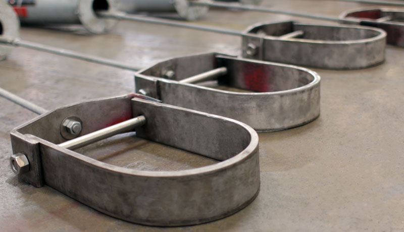
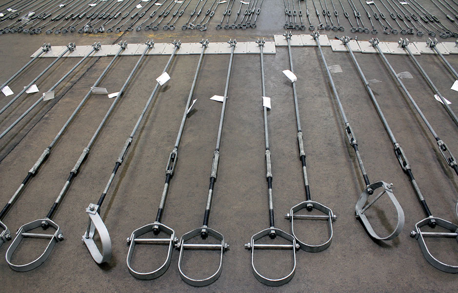
Clevis Hangers

A clevis hanger is a pipe attachment providing vertical adjustment, consisting of a clevis type top bolted to a formed steel bottom strap. They are recommended for the suspension of non-insulated, stationary pipe lines.

Ammonia Plant
Chemical Plant
Clean Fuels
Commercial

Electric Plant
Energy Facility
Ethylene Plant
LLDPE Chemical Plant

LNG Plant
MTBE Plant
Natural Gas Combined Cycle Facility
Natural Gas Processing & Separation

Oil Refinery
Oil Sand Mine
Paper Manufacturer
See All

See More Images

A trapeze hanger is a support assembly consisting of parallel vertical rods which are suspended from a structure and connected ...Continue Reading


More FAQs…

GENERAL DIMENSIONS & SPECIFICATIONS

Download PDF

Fig. 83: Adjustable Clevis Hanger

Fig83

SIZE RANGE: 1/2 inches thru 30 inches
MATERIAL: Carbon steel
FINISH: Black or galvanized: furnished galvanized unless otherwise specified.
SERVICE: Recommended for the suspension of non-insulated, stationary pipe lines.
MAX. TEMP: 650°F.
FEATURES: Designed with the yoke on outside of lower U-Strap so the yoke cannot slide toward the center of the bolt, thus bending of the bolt is minimized. Spacer sleeve used for size 16” thru 36”.
COMPONENTS: Top yoke, bottom strap, and bolt or stud with nut-assembled.
INSTALLATION: Hanger load nut ABOVE clevis must be tightened securely to assure proper hanger performance.
ORDERING: Specify figure number, pipe size, description and finish.
NOTE: Punched forming holes may be present on certain sizes of this clevis hanger. These holes are solely for the purpose of manufacturing and do not affect the structural integrity or load carrying capacities of these hangers.

PIPE SIZEMAX. RECOM. LOAD, lbs.WEIGHT (APPROX.) lbs. per 100SIZE OF STEELABCDEADJUSTMENTG
UpperLowerF
1/2730341/8 x 11/8 x 13/81 11/162 1/82 1/27/87/161/4
3/4730391/8 x 11/8 x 13/81 7/82 7/162 1/211/21/4
1730441/8 x 11/8 x 13/82 1/82 13/162 1/21 1/45/81/4
1 1/4730451/8 x 11/8 x 13/82 9/163 7/162 1/21 3/47/81/4
1 1/2730551/8 x 11/8 x 13/8342 1/22 1/81 1/161/4
2730611/8 x 11/8 x 13/83 11/164 7/82 1/22 15/161 5/81/4
2 1/213501403/16 x 1 1/43/16 x 1 1/41/24 11/166 1/833 13/1623/8
313501523/16 x 1 1/43/16 x 1 1/41/24 3/46 9/1633 7/81 3/43/8
3 1/213501703/16 x 1 1/43/16 x 1 1/41/24 15/166 15/1634 1/161 3/43/8
414302131/4 x 1 1/43/16 x 1 1/45/85 9/167 13/163 1/24 1/21 15/163/8
514302441/4 x 1 1/43/16 x 1 1/45/86 3/1693 1/25 1/81 3/41/2
619403571/4 x 1 1/23/16 x 1 1/23/46 15/1610 1/845 5/81 7/81/2
820004971/4 x 1 3/43/16 x 1 3/47/88 3/812 5/84 1/472 1/85/8
1036008803/8 x 1 3/41/4 x 1 3/47/89 7/815 1/44 1/28 3/82 1/43/4
12380011423/8 x 21/4 x 27/811 1/2184 1/210 3/1633/4
14420014841/2 x 21/4 x 2112 7/1619 7/165 1/410 13/162 15/167/8
16460021041/2 x 2 1/21/4 x 2 1/2114 1/1622 1/16612 7/162 5/81
18480024421/2 x 2 1/21/4 x 2 1/2115 1/224 3/46 1/213 15/163 7/81 1/8
20480042653/4 x 33/8 x 31 1/417 1/427 3/8714 7/1641 1/4
24480048533/4 x 33/8 x 31 1/419 5/831 5/87 1/217 1/24 1/41 1/4
30600069641 x 33/8 x 31 1/424 1/839 1/88 1/421 7/851 1/4
36—77161 x 33/8 x 31 1/427 1/846 3/168 1/425 1/25 1/21 1/4

Download PDF

Fig. 89: Clevis Hanger for Insulated Lines

Fig89

MATERIAL: Carbon steel
FINISH: Black
FUNCTION:Equivalent to Fig. 83, except bottom has been lengthened to allow covering without interfering with the bolt.
APPROVALS:Conforms to Federal Specification WW-H-171-E, Type 1 and Manufacturers Standardization Society SP-69, Type 1
COMPONENTS: Top yoke, bottom strap, and bolt or stud with nut-assembled.
ORDERING: Specify figure number, pipe size, description and finish.

PIPE

SIZE

MAX. RECOM.

APPROX.

WEIGHT

SIZE OF

STEEL

ADJUST.
 LOAD,

lbs.

lbs. per

100

upper
lower
A
B
C
D
E
F
G
H
1/2
730
44
1/8 x 1
1/8 x 1
3/8
3 5/8
4 3/16
2 1/2
2 7/8
1/2
1/4
2
3/4
730
51
1/8 x 1
1/8 x 1
3/8
3 5/8
4 1/4
2 1/2
2 7/8
1/2
1/4
2
1
730
58
1/8 x 1
1/8 x 1
3/8
4
4 11/16
2 1/2
3 1/4
5/8
1/4
2
1 1/4
730
64
1/8 x 1
1/8 x 1
3/8
4 7/16
5 1/4
2 1/2
3 5/8
7/8
1/4
2
1 1/2
730
72
1/8 x 1
1/8 x 1
3/8
4 3/4
5 3/4
2 1/2
4 1/16
1 1/16
1/4
2
2
730
85
1/8 x 1
1/8 x 1
3/8
7 7/16
8 11/16
2 1/2
6 1/2
1 5/8
1/4
4
2 1/2
1350
191

3/16 x 1

1/4

3/16 x 1

1/4

1/2
8 7/16
9 15/16
3
7 1/2
2
3/8
4
3
1350
201

3/16 x 1

1/4

3/16 x 1

1/4

1/2
8 5/8
10 5/16
3
7 9/16
1 3/4
3/8
4
3 1/2
1350
210

3/16 x 1

1/4

3/16 x 1

1/4

1/2
8 11/16
10 3/4
3
7 3/4
1 3/4
3/8
4
4
1430
247

1/4 x 1

1/4

3/16 x 1

1/4

5/8
9 3/8
11 5/8
3 1/2
8 3/16
1 15/16
3/8
4
5
1430
309

1/4 x 1

1/4

3/16 x 1

1/4

5/8
9 7/8
12 5/8
3 1/2
8 3/4
1 3/4
1/2
4
6
1940
337

1/4 x 1

1/2

3/16 x 1

1/2

3/4
10 5/8
14
4
9 3/8
1 7/8
1/2
4
8
2000
673

1/4 x 1

3/4

3/16 x 1

3/4

7/8
12 3/8
16 3/4
4 1/4
11
2
5/8
4
10
3600
1102

3/8 x 1

3/4

1/4 x 1

3/4

7/8
13 3/4
19 3/16
4 1/2
12 1/4
2 1/8
3/4
4
12
3800
1382
3/8 x 2
1/4 x 2
7/8
15 1/8
21 9/16
4 1/2
13 5/8
2 7/16
3/4
4

Download PDF

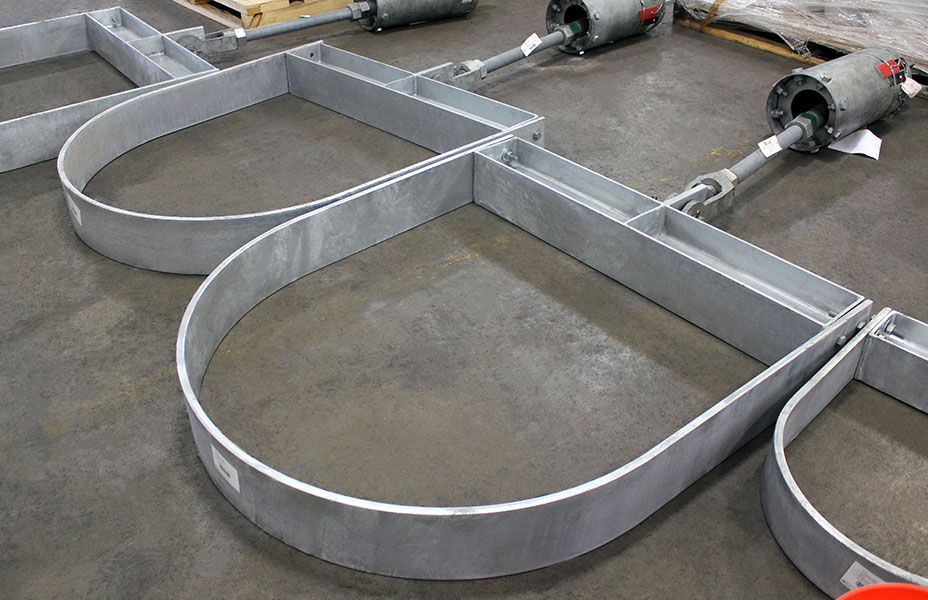
Fig. 195: Roller Hanger

Fig195

MATERIAL: Cast iron roll, carbon steel yoke, roll rod, and hex nuts.
SERVICE: For suspension of pipe from a single rod where horizontal movement may occur because of expansion or contraction.
HOW TO SIZE: If the roll is to support bare pipe, select the size directly from the nominal pipe size (see table below).
ORDERING: Specify figure number, pipe size, description and finish.

NOMINAL

PIPE SIZE

MAX. O.D.

OF COVERING

MAX.

RECOM. LOAD, lb.

APPROX.

WEIGHT (lb. per 100)

A
B
C
D
E
F
G
H
2 1/2
3
225
170
1/2
5 3/4
3 1/4
1 15/16
2 7/8
1/2
3/16 x 1
1 11/16
3
3 5/8
310
220
1/2
6 3/8
3 7/8
2 1/4
3 1/8
1/2
1/4 x 1
1 5/8
3 1/2
4 1/8
390
253
1/2
7
4 3/8
2 9/16
3 1/2
1/2

1/4 x 1

1/4

1 11/16
4
4 11/16
475
321
5/8
7 9/16
4 15/16
2 13/16
3 5/8
1/2

1/4 x 1

1/2

1 5/8
5
5 3/4
685
627
5/8
9 1/8
6
3 7/16
4 1/2
5/8

3/8 x 1

3/4

1 15/16
6
6 7/8
780
927
3/4
10 5/16
7 1/8
4
5
3/4
3/8 x 2
1 7/8
8
9
780
1454
7/8
12 11/16
9 1/4
5 1/8
6 1/8
7/8

3/8 x 2

1/2

2
10
11
965
1880
7/8
15 1/16
11 1/4
6 3/8
7 1/4
7/8

3/8 x 2

1/2

2 1/16
12
13
1200
2774
7/8
17 7/16
13 1/4
7 7/16
8 3/8
1

1/2 x 2

1/2

2 1/4
14
14 1/4
1200
3913
1
18 7/8
14 1/2
8 3/8
8 3/4
1 1/8

1/2 x 2

1/2

2
16
16 1/4
1200
4905
1
20 13/16
16 1/2
9 3/8
9 11/16
1 1/4

1/2 x 2

1/2

1 15/16
18
18 1/4
1400
5780
1 1/8
23 3/4
18 1/2
10 7/16
11 7/16
1 1/4
1/2 x 3
2 11/16
20
20 1/4
1600
7594
1 1/4
26
20 1/2
11 5/8
12 1/4
1 3/8
5/8 x 3
2 1/2

Download PDF

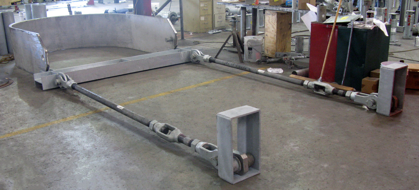
Fig. 200: Trapeze Roller Hanger

Fig200

MATERIAL: Cast iron roll and sockets; steel roll rod.
SERVICE: For suspension of pipe from two rods where longitudinal movement due to expansion or contraction may occur.
ADJUSTMENT: Adjustment socket permits vertical adjustment at the roll.
HOW TO SIZE:
1. If the roll is to support non-insulated pipe, select the size directly from nominal pipe size.
2. If used with pipe covering protection saddle, see Fig, 184, 185, 186, 187, 188, and 189 for size of pipe roll.
3. If roll is to support covered pipe, select the nominal pipe size (column 1) which corresponds to the O.D. of covering and saddle (column 2).

ORDERING: Specify figure number, nominal pipe size, description and finish.

NOMINAL

PIPE SIZE

MAX. O.D.

OF COVERING

ADJUSTED

SOCKET No.

MAX.

RECOM.SAFE LOAD

(lb.)

APPROX.

WEIGHT

(lb. per 100)

A
B
C
D
E
F
G
H
J
1
2
1 — 3/8
600
45
4 1/8
3
1 1/2
1
3/4
3/8
3/8
1 1/16
9/16
1 1/4
2 1/2
1 — 3/8
600
48
4 1/2
3 3/8
1 7/8
1 1/16
3/4
3/8
3/8
1 1/4
9/16
1 1/2
2 3/4
1 — 3/8
600
51
4 3/4
3 5/8
2 1/8
1 1/8
3/4
3/8
3/8
1 3/8
9/16
2
3 1/4
1 — 3/8
600
57
5 1/4
4 1/8
2 5/8
1 3/16
3/4
3/8
3/8
1 5/8
9/16
2 1/2
3 3/4
2 — 1/2
660
100
6 1/4
4 7/8
3 1/8
1 3/8
7/8
1/2
1/2
1 15/16
11/16
3
4 1/2
2 — 1/2
700
110
6 7/8
5 1/2
3 3/4
1 7/16
7/8
1/2
1/2
2 1/4
11/16
3 1/2
5
2 — 1/2
750
135
7 1/2
6 1/8
4 1/4
1 5/8
1
1/2
1/2
2 9/16
3/4
3 — 1/2
150
7 3/4
6 1/4
5/8
3/4
4
5 1/2
2 — 1/2
750
150
8
6 5/8
4 3/4
1 3/4
1
1/2
1/2
2 13/16
3/4
3 — 1/2
165
8 1/4
6 3/4
5/8
3/4
5
7
2 — 5/8
750
226
9 7/16
8 1/16
5 13/16
2
1 1/8
5/8
1/2
3 7/16
13/16
3 — 5/8
257
9 11/16
5/8
7/8
6
8 1/4
2 — 3/4
1070
378
10 15/16
9 9/16
6 7/8
2 5/16
1 1/4
3/4
1/2
4
7/8
3 — 3/4
416
11 3/16
5/8
1
4 — 3/4
445
11 7/16
3/4
1
8
10 1/2
2 — 7/8
1350
585
13 5/16
11 15/16
8 7/8
2 13/16
1 1/2
7/8
1/2
5 1/8
15/16
3 — 7/8
625
13 9/16
5/8
1 1/16
4 — 7/8
690
13 13/16
3/4
1 3/16
5 — 7/8
715
14 1/16
7/8
1 1/8
10
12 3/4
2 — 7/8
1730
838
15 7/16
14 1/16
11
3 3/8
1 3/4
7/8
1/2
6 3/8
15/16
3 — 7/8
862
15 11/16
5/8
1 1/16
4 — 7/8
920
15 15/16
3/4
1 3/16
5 — 7/8
950
16 3/16
7/8
1 1/8
12
14 3/4
3 — 1
2400
1465
17 7/16
15 13/16
12 1/2
3 7/8
2
1
5/8
7 7/16
1 1/8
4 — 1
1525
17 11/16
3/4
1 1/4
5 — 1
1590
17 15/16
7/8
1 1/4
14
16 1/4
5 — 1 1/8
3130
2360
19 7/8
17 3/4
14 1/4
4 5/8
2 1/2
1 1/8
7/8
8 3/8
1 7/16
6 — 1 1/8
2425
20 1/8
1
1 3/8
16
18
5 — 1 1/4
3970
3080
21 7/8
19 3/4
16 1/4
5
2 5/8
1 1/4
7/8
9 7/16
1 1/2
6 — 1 1/4
3185
22 1/8
1
1 1/2
7 — 1 1/4
3260
22 3/8
1 1/8
1 1/2
18
20 1/4
5 — 1 1/4
4200
3370
24
21 7/8
18 1/4
5 7/16
2 3/4
1 1/4
7/8
10 1/2
1 1/2
6 — 1 1/4
3475
24 1/4
1
1 1/2
7 — 1 1/4
3550
24 1/2
1 1/8
1 1/2
20
22 1/2
8 — 1 3/8
4550
4700
27 1/4
24 1/4
20 1/4
6
3
1 1/4
1 1/4
11 5/8
1 5/8
24
26 1/2
6 — 1 1/2
6160
7255
31
28 5/8
24 1/4
7 3/16
3 5/8
1 1/2
1
14
1 13/16
7 — 1 1/2
7365
31 1/4
1 1/8
1 15/16
8 — 1 1/2
7500
31 5/8
1 1/4
2 1/16
9 — 1 1/2
7630
32 1/8
1 1/2
1 3/4
30
32 1/2
8 — 1 7/8
7290
12690
38 1/2
35 1/2
30 1/4
8 15/16
4 1/2
1 3/4
1 1/4
17 7/16
2 1/4
9 — 1 7/8
12990
39
1 1/2
2 7/16

10 — 1

7/8

13400
39 7/8
1 7/8
2 1/8

hbspt.forms.create({
portalId: “88145”,
formId: “387a2f0a-000b-4fec-ace9-674cd4cf472e”
});

Top