PLACING PT&P VARIABLE SPRING HANGERS IN PDS (Plant Design System)
*The following steps will navigate you through the corresponding bitmap forms.
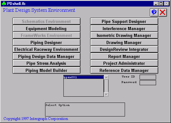
1) PDShell Form
* From the PDS main menu, choose Pipe Support Designer
* Alternate route: Choose Piping Designer >> File Options >> Switch to Pipe Supports
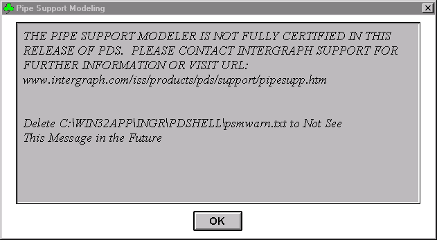
2) Pipe Support Modeling
* PT&P code can be downloaded from the below URL.
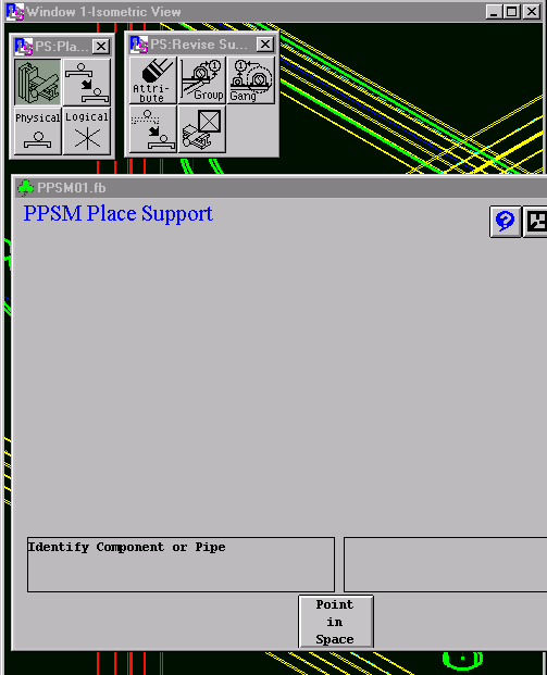
3) PPSM Place Support
* Choose the area in which to place pipe support.
* Choose the model in which to place pipe support.
* Choose Place Support from the Place menu.
4) Identify Pipeline
* The form for placing asks for a pipeline to be identified. Choose a pipeline and confirm selection.
* Choose a support group. In this example, we will place a variable spring. Choose the Support Detail/Commodity box and enter a support number or tag.
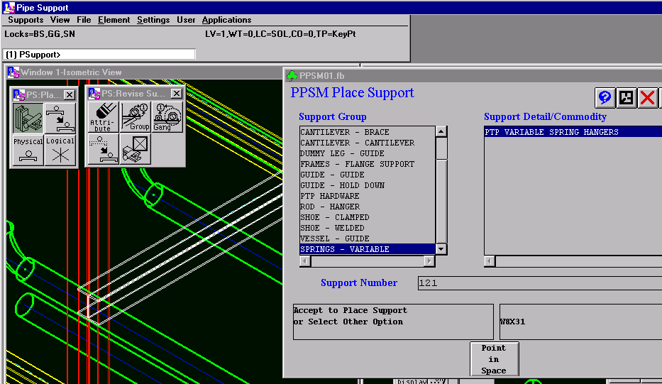
5) Choose Overhead Beam
* Choose an overhead beam to use as supporting steel. Tentative-click and then confirm the steel member.
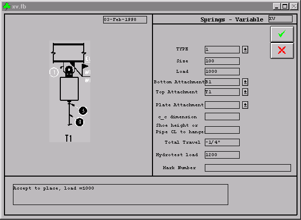
* Fill the form parameters according to the below descriptions. These numbers are only used to demonstrate what inputs go into the form.
6) Using Forms & Their Options
HOW TO USE FORMS AND THEIR OPTIONS
XV FORM
TYPE —————————— Enter 1, 2, 4, 6, or 8 Depending on the PT&P type
SIZE —————————— Enter 0, 10, 20, …, 210, or 220 Depending on the PT&P size
LOAD —————————— Enter load in pounds as an integer ( 1000 ) without PT&P tare weight included
BOTTOM ATTACHMENT ——
B1 is a three bolt clamp
B2 is a lug for an elbow
B3 is a lug along the pipe
B4 is a trapeze assembly or PT&P type G
B5 is a base can supporting the pipe from below
TOP ATTACHMENT ————-
T1 is a PT&P type C hanger spring with a welded beam attachment, Fig. 20
T3 is a PT&P type A hanger spring with a welded lug attachment, Fig. 72
T4 is a PT&P type D that rests on top of a pair of channels with or without a support plate
TOP PLATE ATTACHMENT —
T5 is a 4X9 plate (for 3/8″ to ¾” rod sizes)
T6 is a 12×12 plate (for 7/8″ to 2-1/2″ rod sizes)
C-C DIMENSION —————— The centerline to centerline distance for a trapeze hanger
SHOE HEIGHT OR —————- Shoe height for B4 (trapeze type assembly) or
PIPE CL TO HANGER ———— Distance from pipe centerline to bottom of spring hanger for T3.
TOTAL TRAVEL —————— Total movement expected by the pipeline, upward is positive.
7) Accept The Form
* Accept the form by clicking the green check mark.
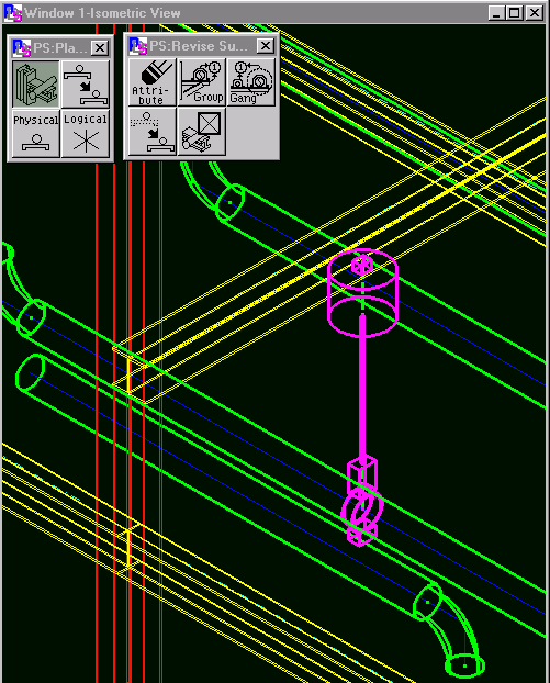
* The following graphics should appear in the model.
