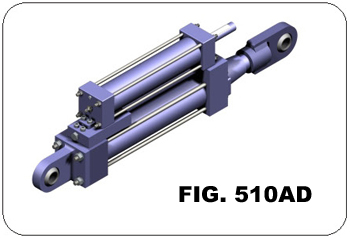
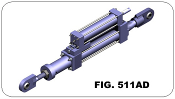
Fig 510AD & 511AD


ORDERING: Specify figure number, description, cylinder size, stroke, load, thermal movement, overall length, and piston end option. If a pipe clamp is required, please specify nominal pipe size or special O.D., pipe temperature, and any additional option features (i.e. integral relief valve or remote reservoir mounting) or special settings required.
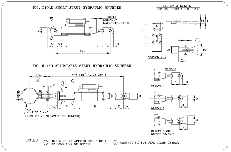
Fig. 510AD – SHORT STRUT HYDRAULIC SNUBBER
| Cylinder | Approx. Weight (1) | H Min. (2) |
P-P Min. (2) | Load Rating (KIPS) | A | B | D | D1 | E | G | L | M | W1 | S | BB | |
| Size | Stroke | |||||||||||||||
| 1 1/2 | 6 | 35 | 16 | 21 | 3 | 2 | 3/4 | 2 1/2 | 2 3/4 | 3 | 1 1/16 | 1 1/4 | 5 | 2 | 3/4 | 0.656 |
| 12 | 42 | 22 | 27 | |||||||||||||
| 18 | 50 | 28 | 33 | |||||||||||||
| 2 1/2 | 6 | 70 | 16 1/2 | 23 1/4 | 10 | 2 1/2 | 1 | 3 | 3 1/2 | 3 3/4 | 1 1/2 | 1 3/4 | 6 | 3 | 1 | 0.875 |
| 12 | 83 | 22 1/2 | 29 1/4 | |||||||||||||
| 18 | 96 | 28 1/2 | 35 1/4 | |||||||||||||
| 3 1/4 | 6 | 125 | 17 3/8 | 27 1/8 | 20 | 4 | 1 1/2 | 5 | 4 3/4 | 5 1/2 | 2 1/2 | 2 1/4 | 7 3/8 | 4 1/4 | 1 1/2 | 1.312 |
| 12 | 145 | 23 3/8 | 33 1/8 | |||||||||||||
| 18 | 165 | 29 3/8 | 39 1/8 | |||||||||||||
| 4 | 6 | 155 | 17 3/4 | 28 1/2 | 30 | 4 | 1 1/2 | 5 | 4 3/4 | 6 1/2 | 2 1/2 | 2 1/2 | 8 1/2 | 4 1/4 | 1 1/2 | 1.312 |
| 12 | 180 | 23 3/4 | 34 1/2 | |||||||||||||
| 18 | 205 | 29 3/4 | 40 1/2 | |||||||||||||
| 5 | 6 | 255 | 18 1/4 | 31 3/4 | 50 | 5 1/2 | 2 | 7 | 6 | 8 | 3 1/2 | 3 1/4 | 10 1/4 | 5 1/2 | 1 7/8 | 1.75 |
| 12 | 290 | 24 1/4 | 37 3/4 | |||||||||||||
| 18 | 325 | 30 1/4 | 43 3/4 | |||||||||||||
| 6 | 6 | 410 | 19 1/2 | 33 3/4 | 70 | 6 | 2 1/4 | 7 | 6 1/2 | 8 1/2 | 4 | 3 3/4 | 11 7/8 | 5 3/4 | 2 1/4 | 1.968 |
| 12 | 465 | 25 1/2 | 39 3/4 | |||||||||||||
| 18 | 520 | 31 1/2 | 45 3/4 | |||||||||||||
| 8 | 6 | 805 | 21 3/16 | 41 7/16 | 130 | 8 1/2 | 3 | 10 | 10 | 12 1/2 | 5 1/2 | 4 3/4 | 16 | 7 3/4 | 2 7/8 | 2.625 |
| 12 | 890 | 27 3/16 | 47 7/16 | |||||||||||||
| 18 | 975 | 33 3/16 | 53 7/16 | |||||||||||||
Fig. 511AD – ADJUSTABLE STRUT HYDRAULIC SNUBBER
| CYLINDER | APPROX. WEIGHT (1) | P-P | F | W MIN. | ||
| SIZE | STROKE | MIN. | (4) MAX. | |||
| 1 1/2 | 6 | 40 | 32 3/4 | 100 | 6 1/4 | 7 1/2 |
| 12 | 47 | 38 3/4 | 100 | |||
| 18 | 54 | 44 3/4 | 100 | |||
| 2 1/2 | 6 | 75 | 36 1/4 | 120 | 7 1/4 | 8 3/4 |
| 12 | 90 | 42 1/4 | 120 | |||
| 18 | 105 | 48 1/4 | 120 | |||
| 3 1/4 | 6 | 130 | 41 5/8 | 120 | 9 1/2 | 9 1/4 |
| 12 | 150 | 47 5/8 | 120 | |||
| 18 | 170 | 53 5/8 | 120 | |||
| 4 | 6 | 200 | 44 1/8 | 120 | 10 1/8 | 9 3/4 |
| 12 | 225 | 50 1/8 | 120 | |||
| 18 | 250 | 56 1/8 | 120 | |||
| 5 | 6 | 330 | 49 1/2 | 120 | 12 1/2 | 10 3/4 |
| 12 | 365 | 55 1/2 | 120 | |||
| 18 | 400 | 61 1/2 | 120 | |||
| 6 | 6 | 530 | 53 3/8 | 120 | 13 3/4 | 11 5/8 |
| 12 | 590 | 59 3/8 | 120 | |||
| 18 | 645 | 65 3/8 | 120 | |||
| 8 | 6 | 1050 | 62 11/16 | 120 | 16 1/4 | 13 3/8 |
| 12 | 1140 | 68 11/16 | 120 | |||
| 18 | 1225 | 74 11/16 | 120 | |||
| Fig. 510AD & 511AD: Dimensions | ||||
| CYLINDER SIZE | A | Fig. 510AD P-P Retracted1 | Fig. 511AD P-P Retracted1 | MAX.RECOM. NORMAL LOAD2 (lb.) |
| 1 1/2 | 2 | 21 | 32 3/4 | 3,000 |
| 2 1/2 | 2 1/2 | 23 1/4 | 36 1/4 | 10,000 |
| 3 1/4 | 4 | 27 1/8 | 41 5/8 | 20,000 |
| 4 | 4 | 28 1/2 | 44 1/8 | 30,000 |
| 5 | 5 1/2 | 31 3/4 | 49 1/2 | 50,000 |
| 6 | 6 | 33 3/4 | 53 3/8 | 70,000 |
| 8 | 8 1/2 | 41 7/16 | 62 11/16 | 130,000 |
| 1Add cold piston setting for install length. These values reflect cylinders having 6" of stroke. 2Load must not be applied utisde 10º included angle cone of action to the pipe clamp axis w/o special authorization. | ||||
|---|---|---|---|---|
