PT&P manufactures a range of standard clamps covering common pipe sizes. These are made of carbon steel and either galvanized or left black. In addition, we frequently fabricate custom clamps for special applications. Application examples include high temperatures requiring alloy steel or those requiring nonstandard dimensions.
In these analyses, we have assumed that the bending radius of forming the ears is 1.5 times the plate thickness. This is the value calculated and used as a practice at PT&P. The AISC recommends that the values are three times the thickness of the plates of 1 to 1-1/2” thickness and four times the thickness for greater thickness. The Finite Element Analysis demonstrates that larger radii would result in lower stresses. These cases prove that finite element analysis at PT&P has led to significantly lower costs to our customers by justifying the use of less steel.
FEA & Specially Designed Clamps
Recently, a stress analysis was conducted of an 82 plastics pipe constrained in the axial direction by a special pipe clamp. PT&P’s final design assumes that three clamps in a series will resist at a total expected axial force of 8,000 lbs. Since the area of the pipe in contact with the support affects the overall stress distribution, it is necessary to determine how much contact there is at different pressures via FEA in two steps.
Step #1
The first step establishes whether or not the stresses in the clamp and pipe
 were in acceptable limits and fixes a starting condition for the remainder of the analysis. Here, the clamping force (estimated to be 13,300 lbs.) alone acted upon the clamp and pipe. The initial design of the clamp indicated stresses exceeding permissible boundaries by being greater than 50,000 psi. The design was thus modified to alleviate the problem.
Step #2
This step involves determining the highest load achieved before slipping.
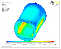
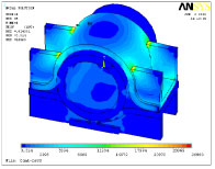
Figure 1 shows stresses on the complete assembly and points that the maximum stress on the clamp is 28,800 psi. The high stress is localized in very small areas at the tip of the gusset. In Figure 2, we have plotted stresses in the plastic pipe only. The maximum stress in the pipe is an acceptable 2,360 psi.
Summary
The maximum stress on the clamp is determined to be 28,800 psi. Stresses in Figure 1 would normally be of little concern in mild steel at typical operating temperatures. If it were a problem, extending the gussets upwards is recommended. In addition, it is recommended to increase pipe length if higher stress is desired. This is due to increased contact between the pipe and clamp, which spreads stress over more area allowing for greater pressures.