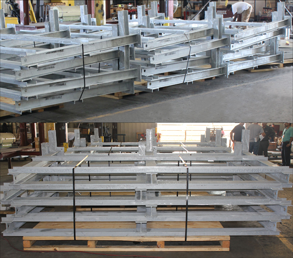
Over 8,000 Instrument Stands Designed for an LNG Facility

Hydraulic Snubber Designed for a Gas Turbine in a Natural Gas-Fired Combined Cycle Generating Power Plant

Hydraulic Snubber Designed For A Gas Turbine In A Natural Gas-Fired Combined Cycle Generating Power Plant

Fronek Anchor/Darling Enterprises Inc., a division of PT&P designed and fabricated this hydraulic snubber assembly for a gas turbine in a natural gas-fired combined cycle generating power plant in Pennsylvania. This fig -510AD is designed for a 10,000 lb. load and a 6″ stroke. It measures 28-1/2″ pin-to-pin and has a 2-1/2″ diameter cylinder. It is designed for an operating temperature of 1052°F and a movement of 4-1/8″. This snubber was tested using the STADAS test machine prior to shipping.

PTFE Slide Plates Designed for an Oil Refinery in Texas


Ptfe Slide Plates Designed For An Oil Refinery In Texas

PT&P custom designed PTFE slide plates for an oil refinery in Texas. These slide plate assemblies are comprised of 3/32″ thick 25% glass filled (PTFE) slide plates bonded to hot dipped galvanized carbon steel backing plates. The assemblies measure 47-1/2″ long by 36-1/2″ wide and 45″ long by 16″ wide. PTFE material provides a low coefficient of friction, is easy to install, does not require surface treatments, or grouting, and is unaffected by weather conditions.

Structural Supports Designed for Instrument Panels in an LNG Facility

Structural Supports Designed For Instrument Panels In An Lng Facility

These structural supports were designed to mount instrument panels in a liquid natural gas facility in Australia. All 72 assemblies were fabricated from carbon steel with a hot-dipped galvanized finish. The dimensions are 68″ x 82″ x 10″ and all assemblies underwent quality control inspection prior to shipment.

F-Type Variable Spring Supports Designed with Stainless Steel Slide Plates and Permanent Travel Stops

F-Type Variable Spring Supports Designed With Stainless Steel Slide Plates And Permanent Travel Stops

PT&P custom designed F-type variable spring supports for an oil refinery in Saudi Arabia. These assemblies range in height from 14-1/4″ to 39-3/8″ and include stainless steel slide plates and upper permanent travel stops. Some of the variables include an additional pipe extension to meet the installation height requirement. The variables are fabricated from carbon steel and painted with a special paint to resist corrosion. All variable assemblies underwent a standard variable spring test prior to shipment.

B-Type Constant Spring Supports Designed for a Hydrocracker Application

B-Type Constant Spring Supports Designed For A Hydrocracker Application

PT&P manufactured B type constant spring supports for a hydrocracker application at a refinery in Port Author, TX. These custom designed constants are 83″ x 41″ x 20″, and designed to support a 53,000 lb. riser pipe through two trunnions. The constants are designed for an operating load of 26,700 lb. with 10-1/2″ of total travel. They are fabricated from A36 carbon steel and underwent standard load and travel testing prior to shipment.

G-Type Variable Spring Supports Designed for a Chemical Plant

G-Type Variable Spring Supports Designed For A Chemical Plant

PT&P designed G-Type variable spring supports for a chemical plant in Texas. The variables are comprised of two standard spring housing joined together with an intermediate bridge assembly. The bridge assembly is customized to match existing site conditions which allows for use in applications with limited space or interferences. The variables are fabricated from carbon steel with a hot-dipped galvanized finish. The assemblies were designed for a total operating load of 23,522 lb. with a downward design travel of 3/8″. Each assembly underwent a standard load test prior to shipment.

In piping and fittings, what all is included in the combination of parameters?

Included is noise, vibration, erosion, cavitation, compression, efficiency, cost, pressure, differential, temperature and flow rate.

In pipings and fittings, how is stress managed?

Allowable stress levels will be specified in applicable code or standard

In pipings and fittings, what is pressure vessels piping defined by?

Pressure vessels piping is usually defined by ASME Section VIII and includes piping between vessels protected by the same relief valve, piping between vessel and pressure relief safety valve.

In piping and fittings, what is load/pressure capacity?

Load/Pressure capacity is a function of physical attributes of piping use and operating temperature.

In Piping and fittings, what are specs based on?

Specs are specified based on nominal size, schedule and materials of construction.

Hydraulic Snubbers Designed for an LNG Facility in Texas

Hydraulic Snubbers Designed For An Lng Facility In Texas

Fronek Anchor/Darling Enterprises, a division of PT&P, designed snubbers for a LNG facility in Texas. These Fig. 511 AD hydraulic snubbers range in size from 76″ – 85″ piston-to-piston and are fabricated from carbon steel. They are designed for a maximum load of 32,000 lb., 6″ stroke and have a 4″ diameter cylinder. Hydraulic snubbers are designed to protect the piping system when a sudden, heavy load is applied (such as an earthquake of high intensity), which can cause serious vibrations leading to damage and possible failure of the piping system. A cycle test throughout the full stroke from zero to fully extended was performed prior to shipment

In regards to piping system components, what is transmission?

Transmission is sewage service, water lines, natural gas lines, and hydrocarbon lines.

In regards to fluid properties in the piping system, how does energy act?

Energy acts as defined by the first law of thermodynamics.

In regards to fluid properties in the piping system, what is mass balance?

The mass balance formula is the mass of fluid added to system = mass subtracted plus fluid accumulated by system.

In regards to fluid properties in the piping system, what is energy?

Energy is capacity for work by system through work having previously done. When work has been done producing change in motion, position or molecular conditions, system has acquired capacity for work.

In regards to fluid properties in the piping system, how is work described?

When a body is moved against a resistance, work must be done upon the body.

In regards to fluid properties in the piping system, What is the reynolds number?

The Reynolds Number is a dimensionless number. It is defined as the ratio of the dynamic forces of mass flow to the shear stress due to viscosity.

In regards to fluid properties in the piping system, what is viscosity?

Viscosity is resistance of fluid to shear stress, the boundary between fluid and container.
Top