Resources
Resources
FAQ Category: Stress Analysis
FAQ Category: Snubbers, Sway Braces, & Sway Struts
FAQ Category: Slide Plates
FAQ Category: Refineries
FAQ Category: Power Plants
FAQ Category: Piping Systems
FAQ Category: Pipe Support Hardware
FAQ Category: Pipe Shoes, Guides, & Saddles
FAQ Category: Pipe Clamps
FAQ Category: Miscellaneous Fabrication
FAQ Category: Hold-Down Clamps
FAQ Category: General Questions
FAQ Category: Expansion Joints
Happy Holidays From Piping Technology & Products!
Santa counts on us for quality products and so can you!
Please enjoy our annual Holiday video. Happy Holidays from all of us at Piping Technology & Products!
FAQ Category: Engineered Spring Supports
FAQ Category
Basics of Inspection and Maintenance
Piping designers specify supports for piping systems based on the design conditions specified prior to construction. During construction and after years of operation, many of the initial design specs may change, such as operating temperatures, pressures and flow rates. Periodic inspection is necessary to evaluate the status of the individual pipe supports and overall support of the piping system. Safety of the system is an important consideration when considering replacement of individual pipe supports or recalibration of the entire support system.
It is important to understand the original design of the piping system and the function of each individual support prior to inspection. A study of the data sheets, drawings and specifications should establish a picture of how the designer expected the system to operate. Once this is done, then the inspector can focus on what is different at the time of inspection.
Much can be learned through the analysis of data collected by careful inspection of all the supports in the system. Two questions need to be considered:
• Do the individual supports still function as designed?
• Does the system of supports still function as designed?
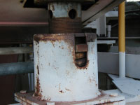
In addition to the physical integrity of the support assembly, the inspector must check the position (amount of compression) of the spring coil. The original designer specified the size for the variable spring support at a certain point based on the load and travel of the pipe expected during start-up, operation, and shutdown cycles of the system. The resistance to movement that a spring coil provides depends on how compressed the coil is. If the indicator shows that the coil is not compressed to the proper position, this means something is different from the what the original piping designer had intended.
When the positions of all the spring coils have been observed, an analysis of the current status of the system can begin. One of the problems which can occur is a bottom out spring. This means the coil is completely compressed and can only move in one direction. This is a major concern for the safety of current operations. An analysis of the total system is necessary to determine if repair or replacement is required or if field adjustments can restore the support system to safely function at current conditions. There are consulting companies who specialize in providing this inspection and analysis service. They also provide training which can be integrated with your safety program.
Checklist for Inspection of Hanger Assembly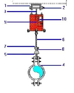
• Check the beam attachment (1), pin (2) and the spring hanger attachment (3) for any cracks, fractures, or signs of corrosion.
• Check the pipe clamp attachment (4), the weldless eye (5) and threaded rod (6) for integrity.
• Test the turnbuckle (7), locknuts (8), and other threaded items to be sure they will turn.
• Check the spring coil (9) for any sign of corrosion.
• Mark the position of the coil (9) on the spring travel indicator (10)
• Check the position of the spring travel indicator(10) and compare it to the design position and the operating range of the spring.
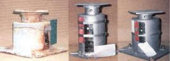
Checklist for a Base Spring Support
1. Same as 4, and 5 above
2. Check the load flange to be sure it can move.
Spring Hanger Replacement
1. Have the replacement spring and associated hardware, along with the necessary tools to complete the removal of the existing spring support and the installation of the new spring support
2. Place the top and bottom travel stops in the existing spring to prevent movement
3. Attach a temporary support to the piping system during removal of the existing spring. Examples of temporary supports: chains and pulleys, rods assemblies, wire, …
4. Remove the existing spring support and related hardware.
5. Install the replacement spring support and related hardware.
6. Remove the lower travel stop and adjust the spring down until the pressure is off the upper stops. Remove the upper stop by hand.
7. Remove the temporary support.
8. Make the final adjustments to hot position on spring scale indicator by adjusting the nuts.
9. Tighten all lock nuts and discard existing spring and hardware.