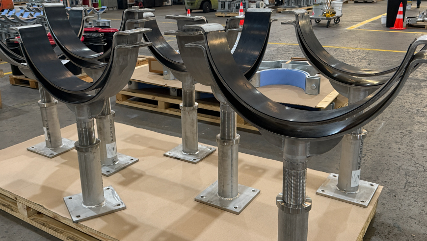
Adjustable pipe supports are essential structural components designed to accommodate post-installation vertical and lateral variations in piping systems. Acting as the load-transfer interface between piping and pipe rack steel, these units provide precise adjustability to correct field tolerances without requiring foundation modifications.
Our product range spans standard adjustable pipe clamp assemblies to heavy-duty pedestals that provide rigid pipe floor support. We specialize in custom fabrication for extreme industrial requirements, having successfully engineered solutions such as a 15ft tall pipe support with a 42 k load capacity. Whether functioning as a base mount or an overhead hanger support for pipes, a reliable pipe support system is crucial for maintaining load balance and preventing stress failures in complex industrial environments.
PT&P Adjustable Pipe Supports PDF
Piping Technology & Products offers a complete line of adjustable pipe supports for midstream applications. We additionally offer complete customization and custom engineering services with all of our adjustable pipe support products. The option to integrate TPI contact corrosion solutions and vibration pads is also available.
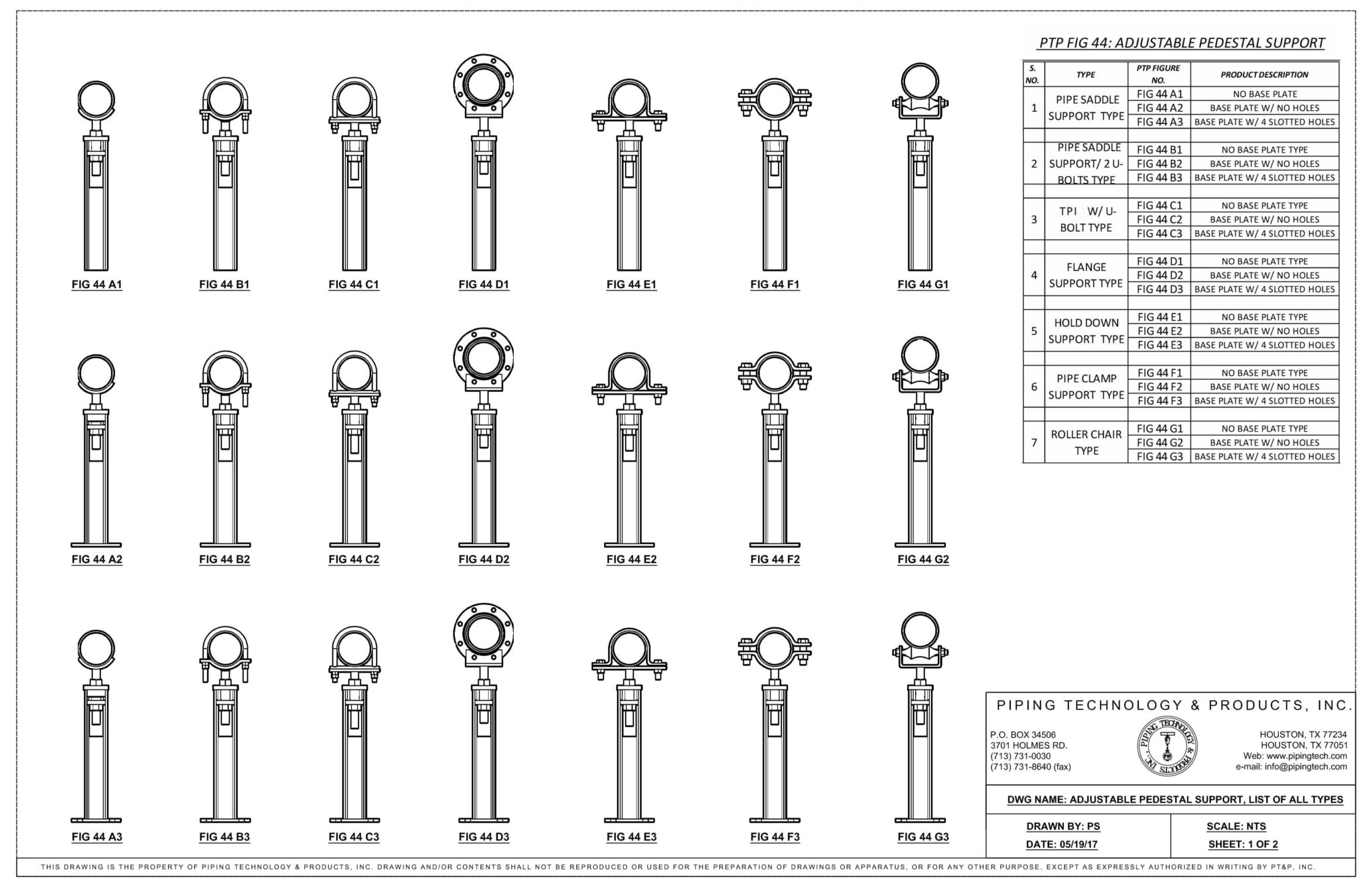
Below is a summary of our various configurations of our adjustable Figure 44 pipe supports. These were developed to target the needs of midstream operations to provide easy adjustability, installation, and longevity.
| S. NO. | TYPE | PT&P FIGURE NO. | PRODUCT DESCRIPTION |
| 1 | PIPE SADDLE SUPPORT TYPE | FIG 44 A1 | NO BASE PLATE |
| FIG 44 A2 | BASE PLATE W/ NO HOLES | ||
| FIG 44 A3 | BASE PLATE W/ 4 SLOTTED HOLES | ||
| FIG 44 A4 | BASE PLATE & SLIDE PLATES | ||
| 2 | PIPE SADDLE SUPPORT/ 2 U-BOLTS TYPE | FIG 44 B1 | NO BASE PLATE TYPE |
| FIG 44 B2 | BASE PLATE W/ NO HOLES | ||
| FIG 44 B3 | BASE PLATE W/ 4 SLOTTED HOLES | ||
| FIG 44 B4 | BASE PLATE & SLIDE PLATES | ||
| 3 | TPI W/ U-BOLT TYPE | FIG 44 C1 | NO BASE PLATE TYPE |
| FIG 44 C2 | BASE PLATE W/ NO HOLES | ||
| FIG 44 C3 | BASE PLATE W/ 4 SLOTTED HOLES | ||
| FIG 44 C4 | BASE PLATE & SLIDE PLATES | ||
| 4 | FLANGE SUPPORT TYPE | FIG 44 D1 | NO BASE PLATE TYPE |
| FIG 44 D2 | BASE PLATE W/ NO HOLES | ||
| FIG 44 D3 | BASE PLATE W/ 4 SLOTTED HOLES | ||
| FIG 44 D4 | BASE PLATE & SLIDE PLATES | ||
| 5 | HOLD DOWN SUPPORT TYPE | FIG 44 E1 | NO BASE PLATE TYPE |
| FIG 44 E2 | BASE PLATE W/ NO HOLES | ||
| FIG 44 E3 | BASE PLATE W/ 4 SLOTTED HOLES | ||
| FIG 44 E4 | BASE PLATE & SLIDE PLATES | ||
| 6 | PIPE CLAMP SUPPORT TYPE | FIG 44 F1 | NO BASE PLATE TYPE |
| FIG 44 F2 | BASE PLATE W/ NO HOLES | ||
| FIG 44 F3 | BASE PLATE W/ 4 SLOTTED HOLES | ||
| FIG 44 F4 | BASE PLATE & SLIDE PLATES | ||
| 7 | ROLLER CHAIR TYPE | FIG 44 G1 | NO BASE PLATE TYPE |
| FIG 44 G2 | BASE PLATE W/ NO HOLES | ||
| FIG 44 G3 | BASE PLATE W/ 4 SLOTTED HOLES | ||
| FIG 44 G4 | BASE PLATE & SLIDE PLATES |
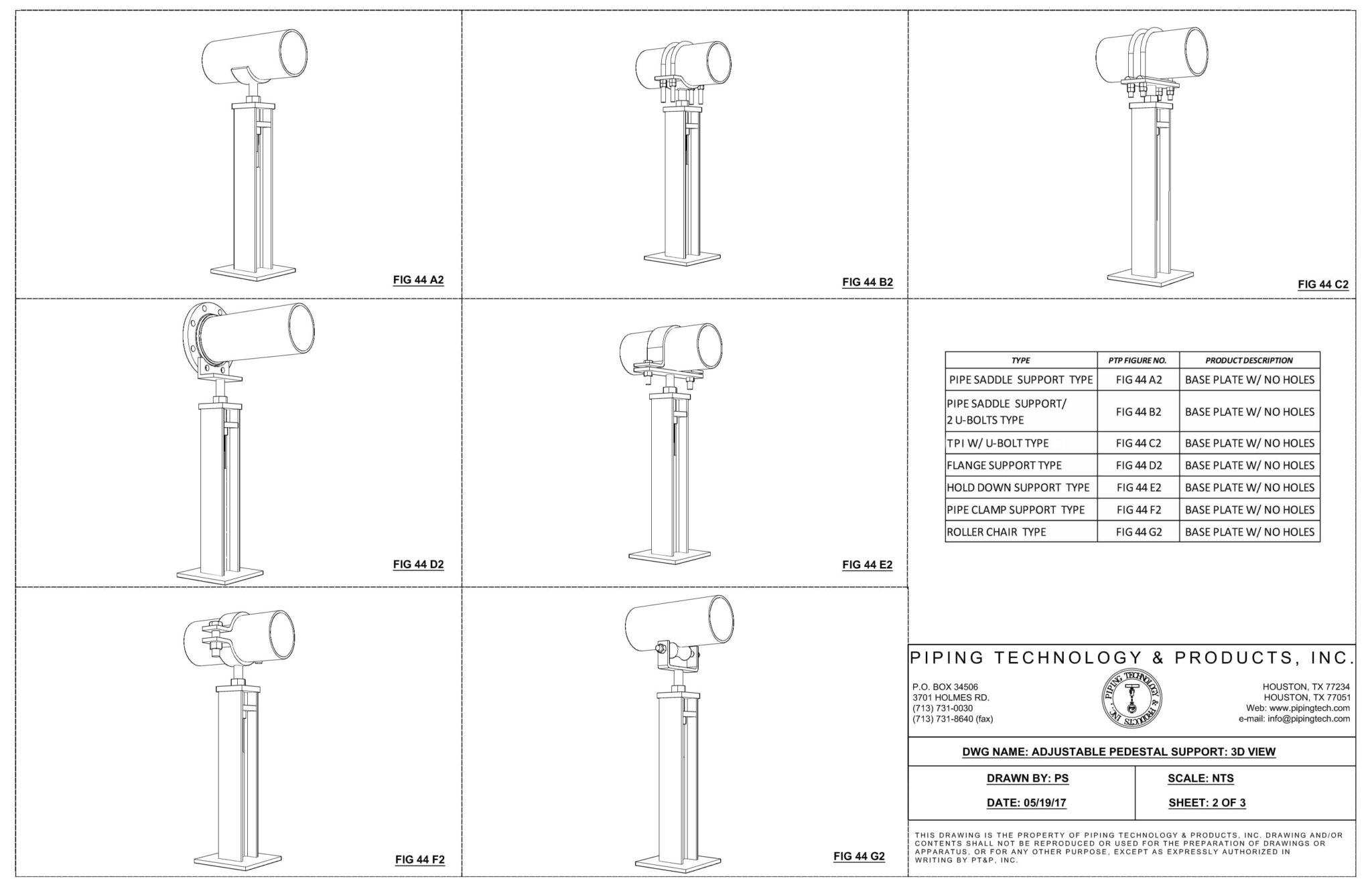
The following are drawings of Fig 44 supports in 2 different views.
Below is the loading information for our Figure 44 supports. NOTE: PT&P can easily customize to customer load and dimensional requirements. We can even do an FEA analysis for highly unusual or custom scenarios.
| PT&P FIG 44: ADJUSTABLE PEDESTAL SUPPORT | |||||
|---|---|---|---|---|---|
| PIPE SIZE | HEIGHT @ COP: 'E' | LOAD (LB) | LATERAL (LB) | AXIAL (LB) | REMARK |
| 2 | 15.25 | 2240 | 900 | 670 | LATERAL LOADS AND AXIAL LOADS ARE APPLICABLE TO... PTP FIG 44B: U BOLTS TYPE PTP FIG 44E: HOLD DOWN SUPPORT TYPE PTP FIG 44F: PIPE CLAMP SUPPORT TYPE |
| 4 | 16.25 | 2950 | 1180 | 885 | |
| 6 | 17.375 | 4750 | 1900 | 1425 | |
| 8 | 18.375 | ||||
| 10 | 19.375 | 6900 | 2760 | 2070 | |
| 12 | 22.375 | ||||
| 14 | 23 | 9300 | 3720 | 2790 | |
| 16 | 24 | ||||
| 18 | 25 | 12300 | 4920 | 3690 | |
| 20 | 27 | ||||
| 22 | 28 | 19900 | 7960 | 5970 | |
| 24 | 29 | ||||
| 26 | 30 | ||||
| 28 | 31 | ||||
| 30 | 32 | ||||
| 32 | 33 | ||||
| 36 | 35 | ||||
The following is the order form for our adjustable pipe supports. (Print order form)
Fig. 46: Adjustable Pipe Saddle Support
| PIPE SIZE | APPROX. WEIGHT lbs. per 100 | A | B | C | D | E | MAX LOAD* | ||
| Complete | Saddle Only | Square | Min. | Max. | |||||
| 2 1/2 | 900 | 480 | 2 1/2 | 3 1/2 | 9 | 1 1/2 | 8 | 13 | 2,000 |
| 3 | 920 | 500 | 2 1/2 | 3 3/4 | 9 | 1 1/2 | 8 1/4 | 13 1/4 | 2,000 |
| 3 1/2 | 940 | 520 | 2 1/2 | 4 | 9 | 1 1/2 | 8 1/2 | 13 1/2 | 2,000 |
| 4 | 1500 | 760 | 3 | 4 1/4 | 9 | 2 1/2 | 9 1/4 | 14 | 3,800 |
| 5 | 1665 | 925 | 3 | 4 7/8 | 9 | 2 1/2 | 10 | 14 3/4 | 3,800 |
| 6 | 1765 | 1025 | 3 | 5 1/2 | 9 | 2 1/2 | 10 1/2 | 15 1/4 | 3,800 |
| 8 | 2020 | 1280 | 3 | 6 7/8 | 9 | 2 1/2 | 11 3/4 | 16 1/2 | 3,800 |
| 10 | 2515 | 1775 | 3 | 8 1/2 | 9 | 2 1/2 | 13 1/2 | 18 1/4 | 3,800 |
| 12 | 2900 | 2160 | 3 | 9 15/16 | 9 | 2 1/2 | 15 | 19 3/4 | 3,800 |
| 14 | 4920 | 3800 | 4 | 10 15/16 | 11 | 3 | 16 1/4 | 20 3/4 | 5,300 |
| 16 | 5320 | 4200 | 4 | 12 3/8 | 11 | 3 | 17 3/4 | 22 1/4 | 5,300 |
| 18 | 7080 | 5100 | 6 | 13 7/8 | 13 1/2 | 3 1/2 | 19 1/2 | 24 | 6,700 |
| 20 | 10480 | 8500 | 6 | 15 3/8 | 13 1/2 | 3 1/2 | 21 | 25 1/2 | 6,700 |
| 24 | 13000 | 11000 | 6 | 17 15/16 | 13 1/2 | 4 | 23 3/4 | 28 1/4 | 7,300 |
| 30 | 17000 | 15000 | 6 | 21 5/16 | 13 1/2 | 4 | 27 | 31 1/2 | 7,300 |
| 32 | 18100 | 16100 | 6 | 22 1/2 | 13 1/2 | 4 | 28 1/4 | 32 3/4 | 7,300 |
| 36 | 24900 | 22900 | 6 | 24 1/2 | 13 1/2 | 4 | 30 1/4 | 34 3/4 | 7,300 |
Fig. 48: Pipe Saddle Support with U-Bolt
| PIPE SIZE | APPROX. WEIGHT (lbs. per 100) | A | B | MAX LOAD |
| 4 | 1075 | 3 | 4 3/16 | 3,800 |
| 5 | 1210 | 3 | 4 13/16 | 3,800 |
| 6 | 1270 | 3 | 5 7/16 | 3,800 |
| 8 | 2130 | 3 | 6 15/16 | 3,800 |
| 10 | 2570 | 3 | 8 7/16 | 3,800 |
| 12 | 3120 | 3 | 9 15/16 | 3,800 |
| 14 | 5000 | 4 | 10 15/16 | 5,300 |
| 16 | 5700 | 4 | 12 3/8 | 5,300 |
| 18 | 6400 | 4 | 13 7/8 | 6,700 |
| 20 | 11350 | 6 | 15 3/8 | 6,700 |
| 24 | 13700 | 6 | 17 15/16 | 7,300 |
| 30 | 14650 | 6 | 19 1/8 | 7,300 |
| 32 | 17400 | 8 | 21 5/16 | 7,300 |
| 36 | 26800 | 8 | 24 1/2 | 7,300 |
FAQ:
Q: Why are adjustable pipe supports necessary for industrial projects?
A: Adjustable pipe supports allow for vertical and lateral fine-tuning after the pipe is installed. This is essential for correcting field discrepancies, accounting for settling foundations, and ensuring the pipe rests uniformly without creating stress concentrations that could damage the system.
Q: How do “adjustable pipe fittings” relate to these support systems?
A: While standard adjustable pipe fittings typically refer to internal plumbing components (like unions or elbows), in the context of supports, we utilize adjustable hardware “fittings” such as turnbuckles, threaded rods, and clevis pins. These components provide the mechanical flexibility needed to lengthen or shorten the support assembly for precise alignment.
Q: What are the advantages of using metallic piping supports over other materials?
A: Metallic piping supports—typically fabricated from carbon steel, stainless steel, or alloys—provide the high load-bearing capacity and thermal durability required for heavy industrial applications. Unlike plastic or composite alternatives, metallic supports maintain structural integrity under extreme heat and pressure.
Q: Can adjustable pipe supports be customized for high-load applications?
A: Yes. Our adjustable pipe supports can be engineered to handle extreme weights (such as the 42k load capacity stands mentioned in our overview). The adjustable mechanism is designed with heavy-duty threads and locking nuts to ensure that once the height is set, it can safely support the piping system.
Q: Are your metallic piping supports compatible with insulated piping?
A: Yes, our metallic piping supports can be designed with protective shields, saddles, or shoes. These additions prevent the support’s hard metal surface from crushing the pipe insulation and ensure the thermal barrier remains intact, while the metallic base provides the necessary structural strength.
Related Adjustable Pipe Supports Resources