Pipe Clamps
PT&P manufactures a range of standard clamps covering common pipe sizes. These are made of carbon steel and either galvanized or left black. In addition, we frequently manufacture custom clamps for special applications. Examples of such applications are high temperatures requiring alloy steel, or applications requiring nonstandard dimensions.
PT&P normally analyzes such special designs using Finite Element Analysis. One reason for this is to ensure that the design has sufficient strength to support expected loads. This is also done to see if the clamp can be made more economically and still function satisfactorily.
FEA & Specially Designed Clamps
Recent examples include two Figure 80 type clamps for a high temperature application. Figure 80 clamps are heavy-duty three-bolt pipe clamps. Due to the high temperature duty, they were made from alloy steel, A387 Grade 91. This steel contains 9% Chromium, 1% Molybdenum and small amounts of Niobium and Vanadium. Both clamps are for 24” pipes, one for a load of 68,200 lbs., and one for 33,500 lbs.
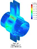
Results: Clamp Test #1
The initial FEA was conducted on the clamp designed to sustain a load of 68,200 lbs. For this load, the PT&P Clamp Sizing program called for a clamp made from two 2” thick x 12” wide strips of steel. This case required the FEA find a maximum stress of 6150 psi. This is considerably less than
the allowable stress for the steel at the operating temperature. As a result, the clamp thickness was reduced to 1-1/2“. It was confirmed that the stresses were again below the allowable.

12 x 2” Clamp for 24” pipe with load of 68,200 lbs
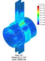
Results: Clamp Test #2
The second FEA was conducted on a clamp designed for a load of 33,500 lbs. According to PT&P’s standard sizing program, this clamp’s design was made from 1-1/2” x 10” steel. The FEA found a maximum stress of 4250 psi, well below the 10,300 psi allowable. Thus, PT&P engineers reduced the size of the clamp to 1-1/4” x 8”, with resulting stress of 7331 psi.

1-1/2 x 10” Clamp for 24” pipe with a load of 33,500 lbs
Conclusions
In these analyses, we have assumed that the bending radius of forming the ears is 1.5 times the plate thickness. This is the value calculated and used as a practice at PT&P. The AISC recommends that the values are three times the thickness of the plates of 1 to 1-1/2” thickness and four times the thickness for greater thickness. The Finite Element Analysis demonstrates that larger radiuses would result in lower stresses. These cases prove that Finite Element Analysis at PT&P has led to significantly lower costs to our customers by justifying the use of less steel.
