The vibration control and sway brace is shipped ready for installation.
1. Measure the correct space required to install the sway brace assembly. Lay out the sway brace assembly as it is to be installed. Weld one end of structural attachment to the structure and affix the other end with clamp or bolting as required. Make sure the sway brace is located in the same direction as the thermal movement of the pipe. Tighten the adjustment coupling to release the travel stops if supplied. Turn the thrust nut until the bottom of the pressure plate lines up with the pre-load indicated on the nameplate.
2. The brace should be in the proper configuration when it reaches the hot condition. If not, final adjustments can be made by tightening or loosening the adjustment coupling.
i) When properly adjusted, the rod coupling should rotate with slight resistance and the tension test collar can be rotated by hand while holding the rod stationary. There should not be any gap between either end of the pressure and end plates.
ii) Two rod ends should be visible in the adjustment coupling.
When the system shuts down for maintenance, the travel stops should be reinstalled and the same adjustment procedure should be repeated.
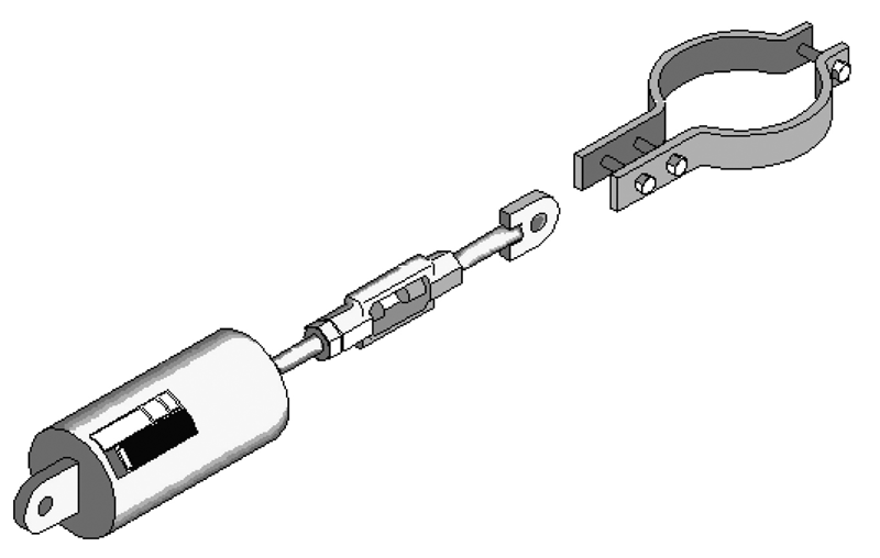
Figure 12: Sway Brace