Piping Technology & Products would like to wish everyone a Happy New Year. Hear what some of our employee’s New Years Resolutions are for 2020!
Resources
Piping Technology & Products would like to wish everyone a Happy New Year. Hear what some of our employee’s New Years Resolutions are for 2020!
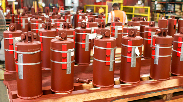
| Type: | Variable Spring Supports |
| Size: | 95-1/16” Overall Length |
| Material: | A36 Carbon Steel |
| Design: | 2,033 lb. Load | 225 lb./in Spring Rate |
| Testing: | Load and Travel Tests |
PT&P custom designed 240 of these Type-C furnace springs for a customer in Indonesia. The assemblies are completely fabricated from A36 carbon steel with a red oxide primer finish. The completed spring hanger assemblies are 95-1/16” overall length. They are designed for an operating load of 2,033 lbs and have a spring rate of 225 lbs./in. To ensure quality the furnace springs had a spring load test report and a spring calibration test to ensure spring rate shall not deviate more than +/- 5% from catalog value.

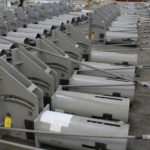
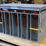
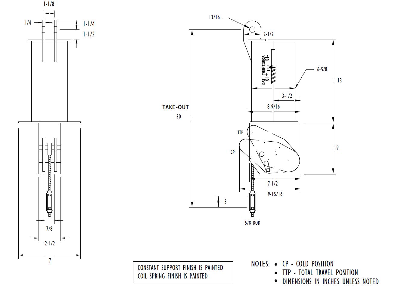
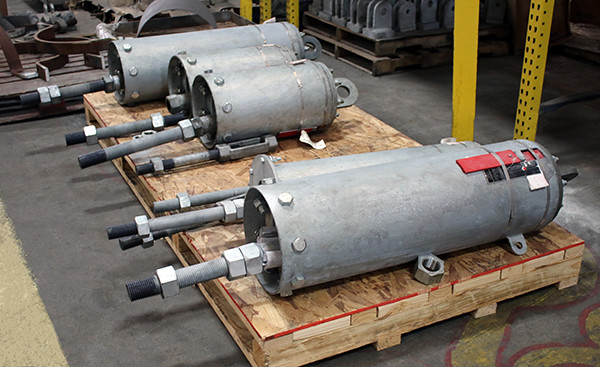
| Type: | Constant Spring Supports |
| Size: | 29″ L x 14″ W x 18-3/4″ H | 76″ L x 26″ W x 37-3/8″ H |
| Material: | A36 Carbon Steel | HDG | Neoprene |
| Design: | 124 lb. to 10,570 lb. Load | 3-1/2″ to 9-1/2″ Travel |
| Testing: | Q.C. Inspection | Load and Travel Tests |
PT&P designed and manufactured U-Type and D-Type constant spring supports for a facility in Mexico. The constants frames are fabricated from A36 carbon steel and have a hot-dipped galvanized coating. The spring coils are alloy steel and have a neoprene coating. The dimensions range from 29” L x 14” W x 18-3/4” H to a max of 76” L x 26” W x 37-3/8” H. The 200-U-Type constants were supplied with graphite plates on the load table. The supports range in load from 124 lb. to 10,570 lb. The total travel ranged from 3-1/2” to 9-1/2”. Standard Q.C., load and travel tests were performed.

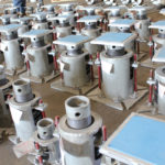
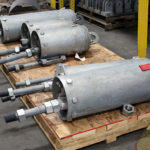
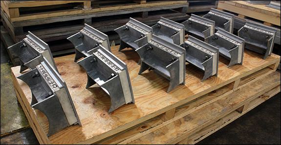
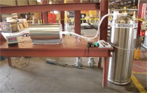
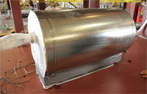
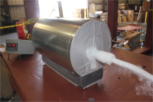
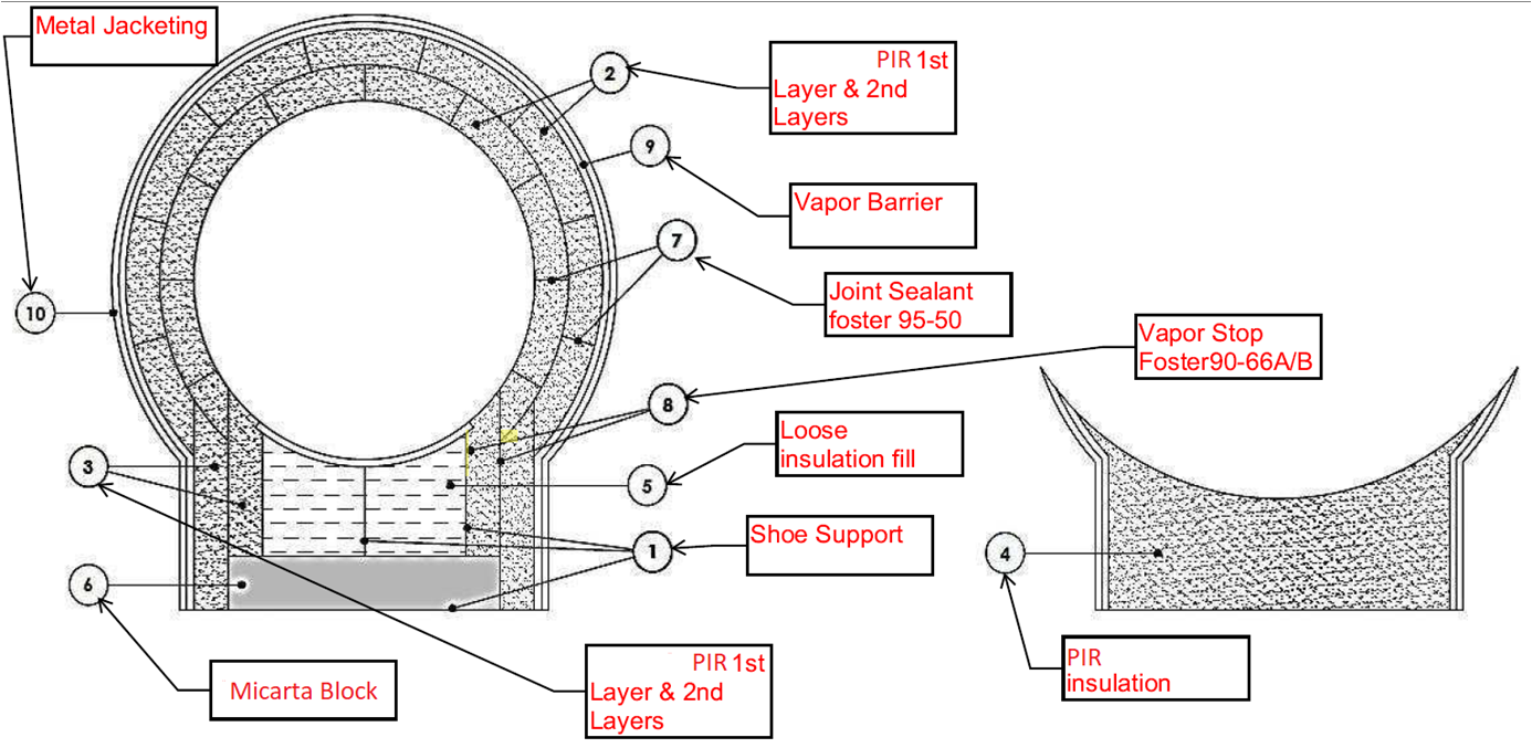
| Type: | Cryogenic Pipe Supports |
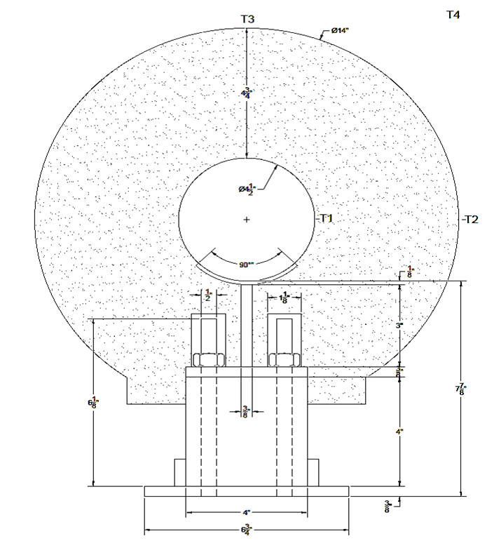
| Size: | 14” L x 4″ W x 6″ H | 2″ Dia. | 2″ Thick Insulation |
| Material: | Polyurethane & Foam Glass | Galvanized Steel |
| Testing: | Q.C. Inspection & Tests |
PT&P manufactured multiple pre-insulated pipe supports for cryogenic temperatures in an ammonia plant in Louisiana. These cryogenic pipe supports, also known as “cold shoes” are designed with 2” thick polyurethane and foam glass for insulation and fabricated from galvanized steel for the shoe, with alloy bolts and nuts. They are 2” diameter 14″ L X 4″ W X 6″ H. These insulated supports are designed for insulating and supporting temperatures down to -300°F with a PSI of 200 to 800. Q.C. inspection and tests were performed prior to shipment.

| Type: | Custom Manifolds with Globe and Gate Valves |
| Size: | 72” Height | 1″ x 1-1/2″ | 1″ x 2” |
| Material: | SA-105 | SA-106B | SA-36 |
| Testing: | 100% Dimensional | Inspection Q.C. Inspection NDE(RT,PT) Hardness | Hydro-test @ 430 PSIG |
PT&P supplied 41 custom manifolds with globe and gate valves to a manufacturing complex in La Porte, Texas. The manifolds were installed in a hot water tracing supply and return system at a high-density polyethylene (HDPE) facility. Each manifold was welded to the exact specifications listed on the production drawing developed. The body was fabricated from 2” and 1” seamless XS pipe. The ports were FNPT and flange connection for field installation. All Manifolds were supplied with welded brackets and vertical support stands. The material used for the valves and flanges were SA-105, pipe SA -106B, and the supports are manufactured from SA-36. The overall height is 72″, and the dimensions are 1″ branches x 1-1/2″ run line and 1″ branches x 2″ run line. Inspection and Q.C. tests were performed by an internal and TPI team including 100 % dimensional inspection, NDE(RT,PT), hardness, and hydro-test at 430 PSIG.
PT&P is setup to offer our customers the absolute best value in Spring Supports. The following are key factors that differentiate PT&P Spring Supports:

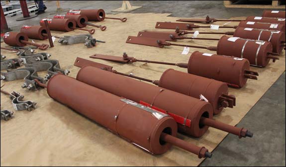
| Type: | Rod Hanger Assemblies |
| Size: | 3-1/2” Diameter | 30′ Long |
| Material: | A36 Carbon Steel | SA-182 F1 | A563 Gr. C | Red Oxide |
| Design: | Custom Designed Length & Diameter |
PT&P custom designed and manufactured sixty rod hanger assemblies for a power plant in North Carolina. The rod diameter is 3 ½” and 30 feet long and utilizes Fig. 95 clevises. The rod material is A36 carbon steel, the clevises from SA -182 F1, and hex nuts from A563 Gr. C. The assemblies were also painted with red oxide primer to protect against corrosion. The rod hangers had to be custom designed because the length and diameter required was not readily available in the marketplace.

| Type: | Bellmouth Reducers, Ring Flanges, Pipe Spool Elbows |
| Size: | 36” NPS | Opened to 48″ NPS |
| Material: | Carbon Steel | 304 Stainless Steel |
| Design: | 150°F | 150 PSI Operating Pressure |
PT&P designed and manufactured bellmouth reducers, ring flanges and custom pipe spool elbows for an Ammonia Plant in Texas. Bellmouth reducers are a single piece component used to transition a large outside diameter into a smaller outside diameter piping. These reducers are used in the cooling process; the shape allows for drawing in maximum amounts of air while preventing loss. The bellmouths are fabricated from carbon steel and 304 stainless steel. They are designed for operating temperatures of 150°F with an operating pressure of 150 PSI. Dimensions are 36” NPS opened to 48” bellmouth. Tests that were performed are spot x-ray, visual and dimensional, PMI-alloys and stainless steel.
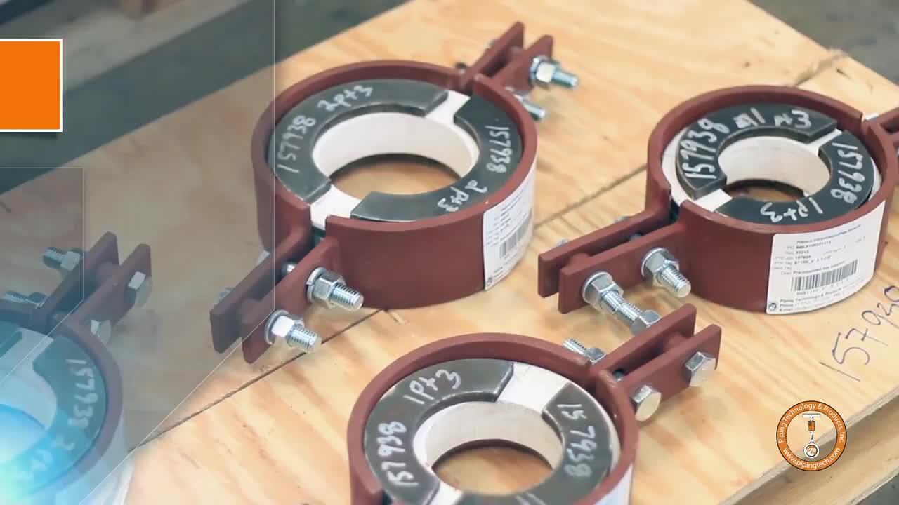
Have a look at PT&P’s pipe clamps
Have a look at PT&P’s high temperature pipe supports (hot shoes)

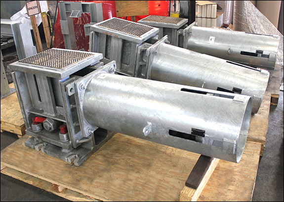
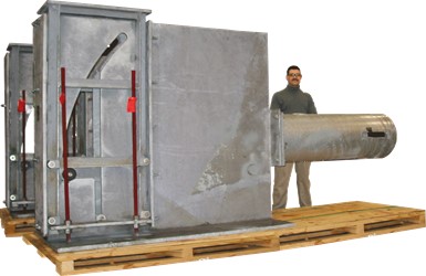
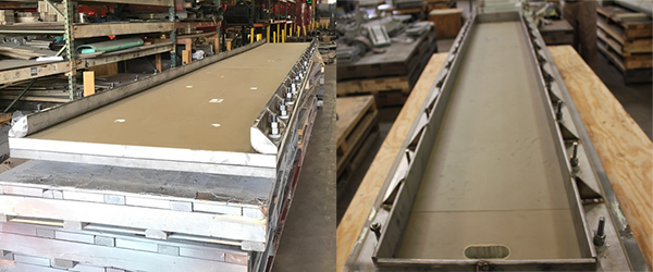
| Type: | High Temperature Pipe Suports (Hot Shoes) |
| Size: | 10” NPS x 6” Hot Insulation x 12” Long |
| Material: | Carbon Steel with HDG finish | Casi & High Density Inserts |
| Design: | 1200°F | 15,000 lb. Vertical | 6,245 lb. Axial |
These pre-insulated high-temperature pipe supports were designed and fabricated for a 10” diameter high-temperature pipeline at a power plant in Arizona. The supports are fabricated from carbon steel with HDG finish and include casi & high-density inserts. They are designed to guide pipes that may reach up to 1200°F, high loads of up to 15,000 lb. vertical and 6,245 lb. axial. There were twenty-nine total “hot shoes” ranging in different designs. The “grooves” in the insulation are for steam tracing. Steam tracing is heat tracing performed by circulating steam around process pipes to heat them. The shoe assemblies are comprised of the four guides on the shoe and adjustable stops. They are designed to account for lateral, vertical, and axial movement. Dimensions for the supports pictured are 10” NPS x 6” thick insulation x 12” long base. Standard tests and Q.C. inspections were performed before shipping.

| Type: | Personnel Protection Shields |
| Size: | 8″ Dia. | Up to 36″ Lengths |
| Material: | Galvanized Carbon Steel |
| Design: | 1050°F Operating Temperature |
PT&P custom designed these personnel protection shields for a power plant in Wyoming. The personnel protection shields are used when insulating the line is not necessary, but operating temperatures require safeguarding personnel from coming into contact with the pipe. These shields are designed for an 8” diameter pipe operating at 1050°F. They are fabricated from carbon steel and range in lengths up to 36”.
|
|
|
|
Materials
|
 |
 |
Finishes
|
 |
 |
DimensionsThe size can be optimized to specific dimension requirements, and customized to fit in restricted spacing. |
 |
 |
LoadWe can supply spring supports with custom load capabilities of Load AdjustmentStandard is +/- 10%, but we can customize up to +/- 60% Load Adjustment) |
 |
 |
TravelStandard is +/- 10%, but we can customize up to +/- 60% Load Adjustment) Travel StopsWe can provide wire or chained travel stops. |
 |
 |
Sensors for Remote MonitoringWe can provide sensors on spring supports to monitor the conditions remotely, and give warning alerts whenever a support does not perform as it should. |
 |
 |
PT&P has developed a unique approach to its manufacturing operation that produces the broadest set of customization options with minimal impact to delivery timeframes. Most producers operate as smaller scale steel fabricators or highly standardized mass production organizations. PT&P is the only organization that is set up for both scales with over 500 production employees, customization capabilities, and artisan manufacturing skills. For example, PT&P is the only Major Global Supplier of both Expansion Joints and Engineered Pipe Supports. This unmatched manufacturing technique was achieved through proprietary systems, a highly engineered approach to manufacturing, and incorporating 10+ Industrial Engineers in the production operation.
| Steel Fabricator (Owner/Operator) | Mass Production | PT&P Mass Customization | |
| Machinery | Simple | Scale | Scale and Artisan |
| Advanced Skills (e.g. TIG welding Inconel) | Varies | Limited | Yes |
| Systems | Limited | For Mass Production | Advanced Systems allow Management of Complexity |
| Customization/Flexibility | High | Low | High |
| Short Turnaround | Yes | No | Yes |
| Scale | Low | High | High |
| Outsourced Offshore | No | Yes | No |
| Engineering Knowledge | Low | Medium | High |
| Ability to Manage Contamination Across Materials | ? | No | Yes |
| Breadth of Product Line | Medium | Low/Medium | Large |
| Target Customer | ? | Major EPCs | All |
Pipe Clamps
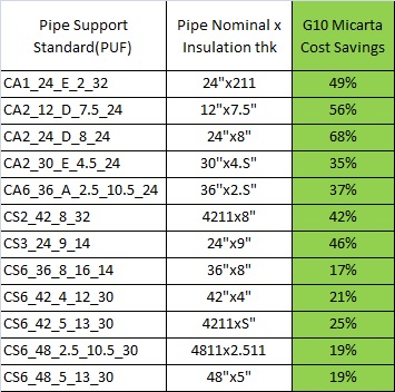
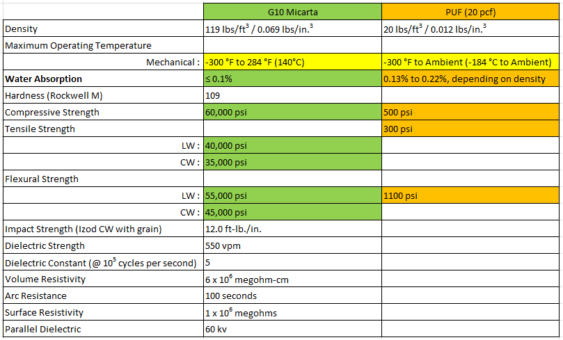
G10 Micarta® can be very cost-effective insulation as compared to Polyurethane foam (PUF), especially for medium and large shoes. It offers tremendous benefits at various stages of a project, including but not limited to:
G10 Micarta® supports involve fewer steps to manufacture, allowing for a quicker fabrication turnaround. It takes 2-3 weeks less on average than PUF supports for delivery. This enables the ability to catch up on deadlines and reduce downtime.
G10 shoes can be sent to the pipe fabricator and can weld directly to the pipe spool, meaning there is minimal installation in the field. It takes 3-5 hours to install a PUF shoe in-field, depending on the size. G10 Micarta® shoes save that FIELD installation time.
Shop welding of G10 Micarta® shoes is much cheaper. As G10 shoes are weld to pipe spool at the fabricator’s shop, they can be inspected and tested in the shop; no inspection and testing in the field. More cost savings as inspection and testing is done at cheaper rates at pipe spool fabricator facilities rather than in the field.
As G10 Micarta® shoes are handled along with the pipe spools, there are fewer chances of missing supports in the field. Less OS&Ds to worry about for both the client and supplier.
G10 Micarta® supports are less fragile than PUF, making the handling, transportation, and storage of G10 to be trouble-free. No special packaging required, saving the time & the cost of special crating. Stronger G10 supports reduce the chances of accidental damage, thereby the need to re-fabricate the support.
G10 Micarta® supports have insignificant water/moisture absorption rate, this means:
 |
 |
 |
 |
 |
 |
 |
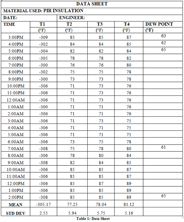
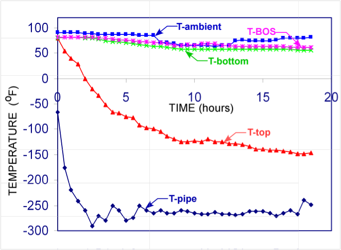
| Time-dependent temperature variations at the stated locations using G-10 Micarta®. (i) T-pipe; (ii) T-top; (iii) T- ambient; (iv) T-Bottom, (v) T-BOS. |
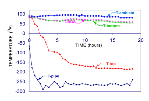
Time-dependent temperature variations at the stated locations using Polyurethane. (i) T-pipe; (ii) T-top; (iii) T- ambient; (iv) T-Bottom, (v) T-BOS. |

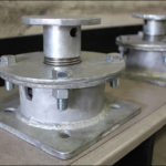
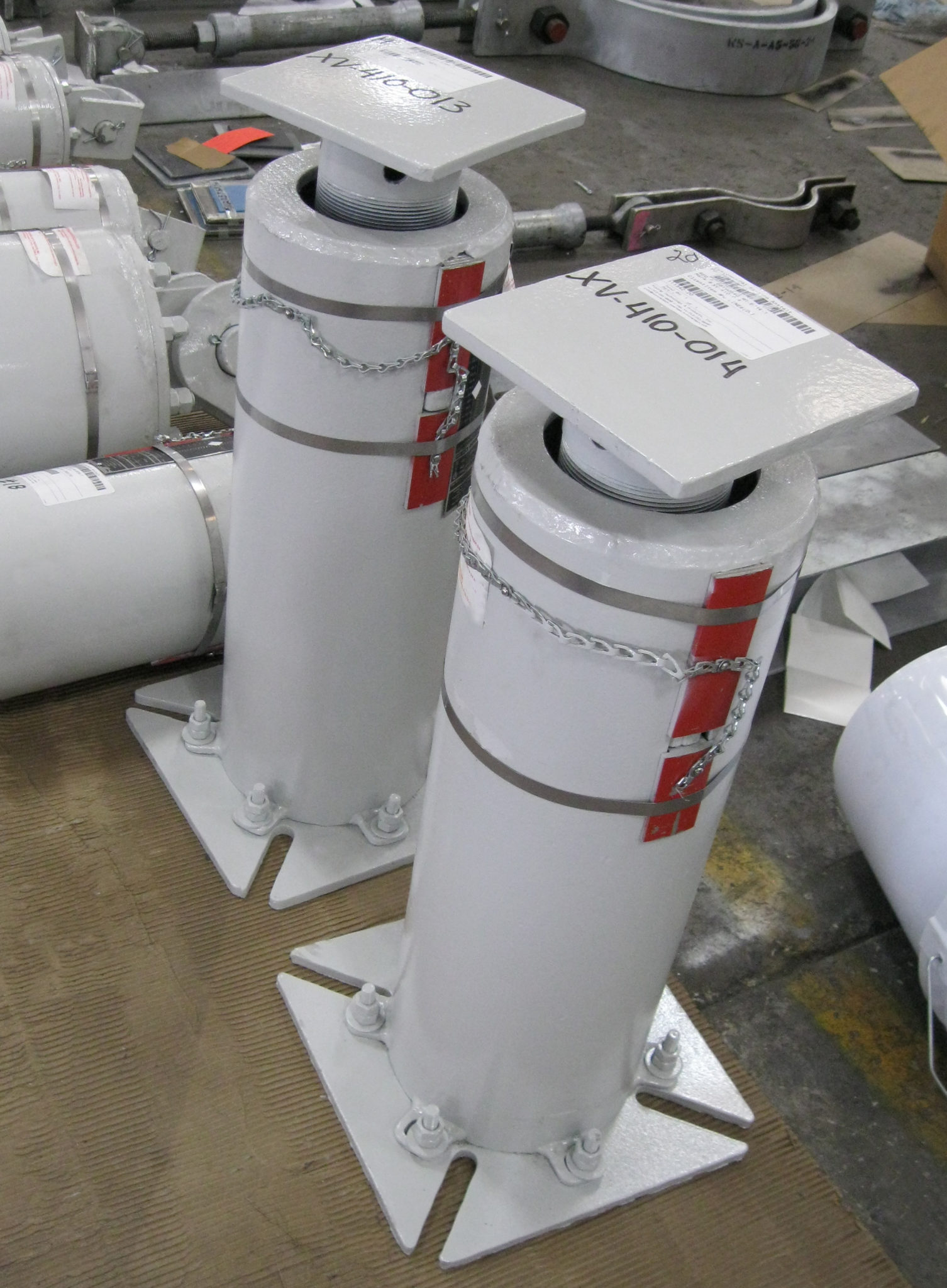
| Type: | Variable Spring Supports w/ PTFE Slide Plates |
| Size: | PTP-4 | 9.5″ – 11.5″ Height |
| Design: | 1/8″ Upward & 3/16″ Downward Travel |
| Material: | HDG Carbon Steel | Gloss Aliphatic Polyurethane Topcoat | PTFE, 25% Glass Filled Slide Plates |
| Testing: | Standard Load Testing & Q.C. Inspection |
Piping Technology & Products, Inc. recently designed and fabricated F-type variable spring supports for a plant in Peru. The variables are fabricated from carbon steel, hot-dipped galvanized and a gloss aliphatic polyurethane topcoat was applied for corrosion protection. PTFE, 25% glass filled, slide plates are bonded to the top of the load flange to reduce the friction caused by lateral movement. The variables range from 9.5″ to 11.5″ in height and are designed for a travel range of 1/8″ upward to 3/16″ downward. To ensure quality, standard load testing was performed prior to shipping.

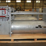
| Type: | Pipe Spools |
| Size: | A36 for flanges and plates, A 106 for pipe, and for stud/nuts A193 B7 |
| Material: | Carbon Steel |
| Testing: | Visual & Q.C. Tests |
PT&P custom designed these Pipe Spools for a plant in Texas. pipe spools are relatively short assembly, consisting of a pre-determined length of pipe welded to a specified fitting (tee, elbow or reducer) or valve (gate or ball), with flanges typically welded at each end of the pipe. The materials used are carbon steel A36 for flanges and plates, A 106 for pipe, and for stud/nuts A193 B7. This order contained 2 pipe spools, ring retainer, pad eyes, & mount supports. Operating loads were 2200 lb. with standard shipping.
Piping Technology and Products has a unique perspective on best practices in preventative maintenance. PT&P has a database built from over 1,000 audits performed in 41 countries. PT&P also has experience from over 3 Million pipe supports and expansion joints currently in service.
The following is a summary of the strategies PT&P sees at operating plants:
The design of the piping system is a major part of the engineering of an operating plant build. On average, piping constitutes 40-48% of the engineering hours in a new refinery. The challenge facing piping engineers is rotating equipment locations and process design are defined and the piping engineers must make the piping system fit within the designated space while dealing with thermal stress, proper flow, and allowable loads for all equipment. With temperatures in high energy lines often well over 1,000 degrees, this can be very challenging. The following are some of the goals of pipe stress engineering and the placement of spring supports and expansion joints in the piping system:
| Strategy | Pros | Cons |
| Fix When Broken |
|
|
| Periodically Fix Broken Springs (Component Level Focus) |
|
|
| Periodically Return to Original Design Specification (System Level Focus) |
|
|
PT&P has seen many examples of each of the strategies above. Typically, the strategy taken at an individual plant is closely related to overall operating philosophy of the organization, including finance. However, we also speak to a number of organizations who have placed an emphasis on preventative maintenance but are not sure of the best practices for the engineered pipe supports and expansion joints.
Appendix A shows an example of a program PT&P executed March of this year on a turnaround. For preventative maintenance, best practice is to not just focus on the health of the piping system components, but on the health of the overall piping system. The following are some of the issues that PT&P has found that cause system level issues:
By the time a plant reaches 10+ years of age, PT&P’s experience is that most plants have encountered one or more of the issues above. For this reason, it is essential to take an approach of resetting the line to the original design specification. Best practices for performing a “reset to design specification” are the following:
The challenge with this approach to preventative maintenance is that it takes a much deeper level of expertise than a component level inspection. PT&P’s experience is that even the ability to operate a pipe stress modeling software program such as CAESAR is far different than a pragmatic understanding of the proper functioning of all the elements of the piping line. Many personnel and firms supporting piping system maintenance are challenged with managing a broad range of equipment at an operating plant, and this can make it difficult to have the depth in pipe stress that may be required to properly execute a system level audit and execute a plant to return the piping system to the original design specification.
The sole purpose of performing audits is to maintain the piping system and equipment to remain in the proper condition. Therefore, the system level (pipe stress audit) that considers the physical condition of the system, along with the spring supports system should be preferred. As mentioned earlier, the component level audit is an important part of the system level which if put together with other system and/or deformation assessment can give the overall picture of the system and finally a better direction for the proper maintenance.
PT&P performed an installed inspection on all the springs supporting a manifold of a heater. The installed (or ”cold”) condition inspection showed that most of the supports were operating properly. However, after performing a second inspection in the operating (or ”hot”) condition, it was concluded that most of the spring supports did not show any signs of movement. This issue was brought up with the customer, and it was determined they were having some issues with the heater tubing affecting the efficiency.
 |
 |
| During Cold Inspection | During Hot Inspection |
Since this issue needed to be addressed to prevent any failures in the future, all the supports from the manifold were assessed and concluded that there is a need for system level repair. Therefore, on a 2019 turnaround, all the spring supports of the manifold were replaced.
The following pictures show that the new supports are moving as designed and system-wide repair was indeed required.
") |
") |
| During Cold Inspection (March 2019) | During Hot Inspection (May 2019) |
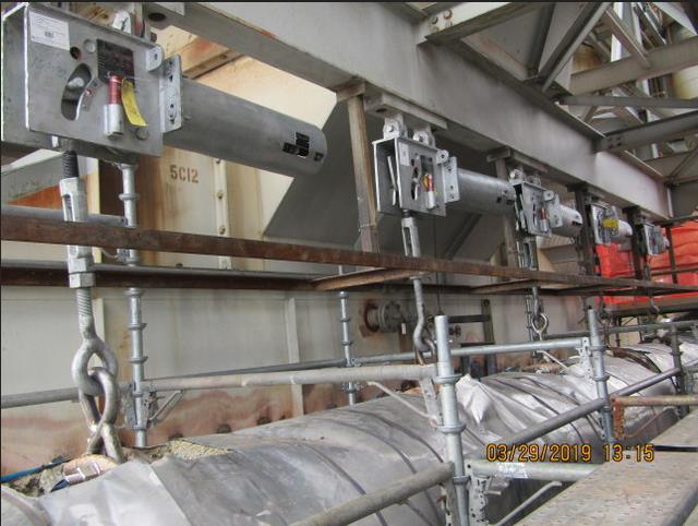
All together 35 spring supports on manifolds were replaced due to failure of previous spring supports.
|
|
In addition to the above, PT&P provided a supervisor (Expansion Joint Technical Expert) to supervise the installation of expansion joints.
PT&P provided two engineers about a year before the turnaround to perform the operating inspection of the spring supports while a cold inspection was done by PT&P in the previous turnaround. All these inspected supports were documented in a report and the conditions were categorized as good, replacement or adjustment required.
Based on the location provided in the inspection report, and constant communication between PT&P engineers and turnaround co-coordinators, the location where the scaffold is to be built was pre-planned.
The materials were purchased a few months before the turnaround. All the required safety training, drug tests, background checks were done prior to the turnaround date.
Out of 10 units, 4 units were “shut down” upon arrival at the site. PT&P engineers performed a quick walk-down on all the spring supports in the units to see if there were any new issues since the last inspection which required immediate attention. This gave enough time to order the materials and necessary hardware.
After the quick inspection, PT&P worked with a few client technicians on two different units. The adjustment and installation work on the two units were done concurrently.
Once those units were completed, PT&P engineers were mobilized to other units. There were a few new discoveries where PT&P engineers ordered materials for adjustment and replacement. Within a couple of days, PT&P managed to supply the parts (shipped through hot shot) and resolve the issues.
There were five times, PT&P provided the materials during the period of turnaround within 48 hours. It was very convenient to have engineers supervising the installation and repair as it allowed for design and/or engineering changes to be made on the spot.
In addition to the pre-planned turnaround work, PT&P engineers assisted, on several occasions, to help resolve issues such as bent struts, check the condition of counterweights (old style), some new expansion work which included the addition of new pipe supports.
Pictures of replaced cans:
 |
 |
| Cracked Spring Support | After Replacement |
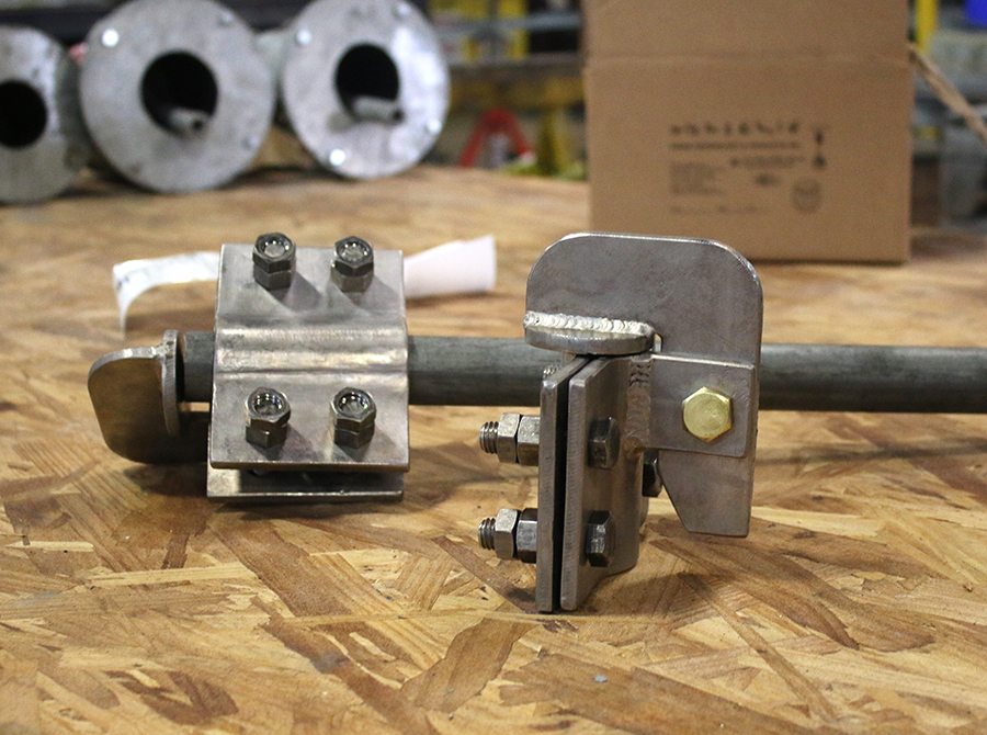
 |
 |
 |
| Bent Rod During Turnaround Work | After Repair | During Follow-up Hot Inspection |
The rod was bent during the turnaround because the contractor working did not reinstall the travel stop while working with the line. The support should have been locked and disengage from the system for this specific work on the pipe coming out of the reactor. The line seemed to have higher movement than anticipated during the turnaround work. This was the second time the rod was bent. PT&P engineers, which were on site for other spring supports work, were contacted immediately. Less than an hour, PT&P field service technicians went and assessed the condition and suggested an improved, robust design. The materials were purchased as per PT&P engineers’ recommendation. Since the order came directly from the field from a PT&P employee, the approval and manufacturing process was smooth and quick. Within a couple of days, the materials arrived and were successfully installed. Everything operated correctly during the follow-up hot inspection.
PT&P supervisor was on site the entire time helping the contractor remove and INSTALL the new expansion joints. Almost all of the CLIENT contractor workers were inexperienced or very limited experience working with expansion joints.
PT&P supervisor gave a quick training about removing and installing the new EJs. They also pointed out the importance of being sensitive towards the EJ fabric since one small improper cut could damage the belt.
PT&P supervisor assisted the contractor with the proper marking of “backing bar” while removing the old EJ. He inspected the condition of the joint and guided contractors to efficiently install the new expansion joint. He also showed the proper way to splice the fabric materials to complete the EJ Installation.

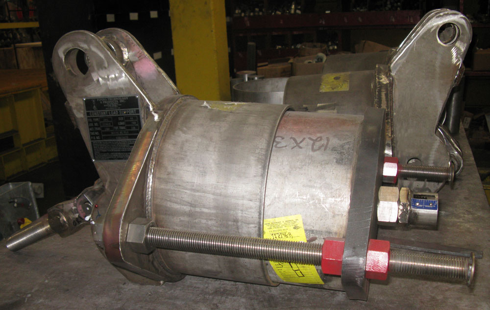
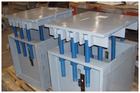
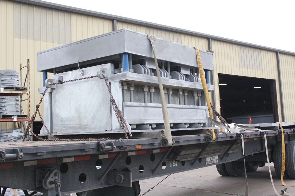
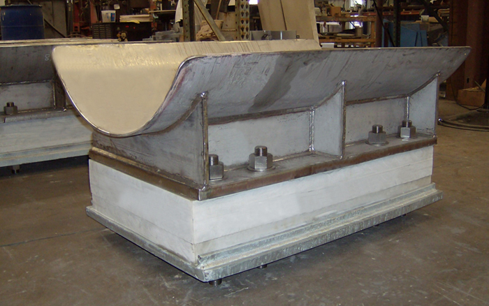
| Type: | Big Ton Spring Supports |
| Size: | 52-3/4″ L x 38-3/4″ W x 91″ H |
| Design: | 121,916 lb. Load | 3/4″ Upwards Movement |
| Material: | HDG Carbon Steel | Neoprene Coated Springs |
| Testing: | Load Calibration Test | Hydro-tested |
PT&P custom designed a big ton spring support for a chemical plant in Pennsylvania. The big ton will be used to support a vessel in excess of 121,916 lb. and a movement of 3/4” upwards. The dimensions for this unit are 52-3/4” L x 38-3/4” W x 91” H. The big ton spring support is designed to support large and heavy units such as compressors, vessels, and pumps in power and petrochemical plants. They are designed to allow limited movement in confined areas. By doing this, it saves the customer from having to entirely redesign the piping system and saves thousands of dollars. The big ton has an internal guide and special pedestal which was designed to meet the required height of the spring and withstand the hydro-test load. A load calibration test was performed before shipping.
 |
|
One of the major challenges faced by many Pipe Support and Expansion Joint manufacturers is trying to serve Major EPCs, Operating Plants, and Mechanical Contractors. The following is a summary of the needs of these different customer groups:
| Major EPC | Mechanical Contractor | Operating Plan | |
| Typical Project | New Plant Build | Small Plant Modification | Maintenance in Turnaround |
| Volume Requirements | Large | Small/Medium | Small |
| Lead Time for Products | Long | Short/Medium | Short/Medium |
| Engineering Support from Vendor | Low | Medium | Medium/High |
| Customization Requirements | Low | Medium | Medium |
| Customer Operating Time Horizon | Turnover of Plant in 1 yr. | Varies | 10+ Years |
The challenge for this mix of customers is that the differences in customer needs’ leads to a fundamental set of choices in terms of manufacturing configuration. Figure 2 shows the choices we see in the marketplace. As can be seen from the table, the big difference is in the target customer for which the operation was designed. The following is a summary of Manufacturing Strategies we have seen:
| Steel Fabricator (Owner/Operator) | Mass Production | PT&P Mass Customization | |
| Machinery | Simple | Scale | Scale and Artisan |
| Advanced Skills (e.g. TIG welding Inconel) | Varies | Limited | Yes |
| Systems | Limited | For Mass Production | Advanced Systems allow Management of Complexity |
| Customization/Flexibility | High | Low | High |
| Short Turnaround | Yes | No | Yes |
| Scale | Low | High | High |
| Outsourced Offshore | No | Yes | No |
| Engineering Knowledge | Low | Medium | High |
| Ability to Manage Contamination Across Materials | ? | No | Yes |
| Breadth of Product Line | Medium | Low/Medium | Large |
| Target Customer | ? | Major EPCs | All |
Most companies do not do mass customization because it is very, very difficult and really takes an engineering, not steel fabrication mindset. The following are some of the key elements that allow PT&P to offer Mass Customization:
Mass Production companies and Steel Fabricators will by their nature be limited in the solutions they can offer. This means they will be tempted to “force fit” customers into their capabilities. The following are just some of the options that PT&P offers with ALL of its products:
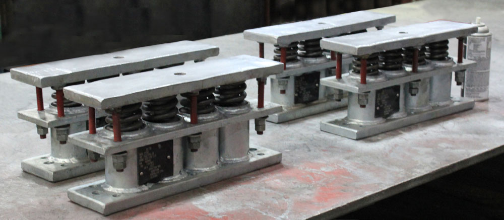
| Type: | B-Type Variable Spring Supports |
| Size: | PTP 100 & 200 | 3′ – 8′ ft. Height |
| Design: | 4,000 lb. – 17,000 lb. Loads |
| Material: | HDG Carbon Steel | Neoprene Coated Springs |
| Testing: | Standard Load Test | Q.C. Tests |
Piping Technology and Products, Inc. recently designed and fabricated B-Type variable spring supports for a plant in Texas. The operating loads range from 4,000 lb. to 17,000 lb. The variable springs are fabricated from galvanized carbon steel, have neoprene coated steel spring coils, and are designed to operate in environments up to 750°F. They have an overall height range from 3 ft. to 8 ft″. To ensure quality, standard load tests were performed prior to shipment.
