Adjustable: Having linear adjustment capability (usually with threads).
Adjustment Device: Components which provide for linear adjustability (e.g.) Turn-buckle, Hanger Rod, Nut, and Load Coupling.
All Thread Rod: A rod threaded its full length. (See Product)
Alloy Pipe Clamp: A Pipe Clamp made from low chrome-moly (less than 5% chrome) materials for the purpose of resisting the effects of piping temperatures in the 750 degrees F. to 1,100 degrees F range. (See Product)
Anchor: A rigid device used to prevent essentially all pipe rotation and displacement at the point of application.
Anchor Bolts: Threaded items used to attach embed plates into concrete on structural supports.
Band Hanger: A Pipe Attachment providing for vertical adjustment, consisting principally of a formed steel strap.
Beam Clamp: A type of forged or fabricated clamp that is used to attach rod hangers to beams by clamping onto the load flange. (See Product)
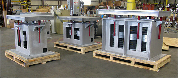
Big Ton Spring: A multi-spring coil device that lends itself to supporting very high loads and providing a great amount of stability. (See Product)
Bracket: Cantilevered member, with or without a kneebrace, designed to withstand a gravity load and/or horizontal forces.
Bulk Material: Material which has been packaged in a manner in which identical items are grouped together and are identified only by quantity, size and/or manufacturer’s figure number.
“C” Clamp: “C” shaped Beam Clamp which attaches to a flange of a structural member and provides for attaching a threaded rod. (See Product)
Center Beam Clamp: A jaw type Beam Clamp for use with I-beams and wide flange beams which provides a centered beam connection for the remainder of the Pipe Hanger Assembly.
Channel Clamp: A Side Beam Clamp with channel adapter and hook rod, which attaches to the bottom flange of a channel beam and provides a connection for the remainder of the Pipe Hanger Assembly.
Clevis Hanger: A Pipe Attachment providing vertical adjustment, consisting of a clevis type top bolted to a formed steel bottom strap. (See Product)
Cold Piston Setting: An indicated piston position on a Hydraulic Snubber, denoting proper installation setting of the unit with the piping in the cold position.
Cold Setting: The position at which a Spring Hanger or Mechanical Snubber indicator is set denoting the proper installation setting of the unit with the piping in the cold position.
Cold Spring: The act of pre-stressing a piping system during installation in order that the equipment reactions will be lower in the operating condition. This pre-stress is accomplished by the proper closure of the Cut Short gaps.
Completely Engineered Hanger Assembly: Pipe Hanger Assembly which has been designed, detailed and provided with a complete bill of material.
Component: Any of a range of devices which are used to make up a Pipe Hanger Assembly.
Concrete Fastener: A device installed in concrete by means of a drilled hole, to which a pipe hanger can be attached.
Concrete Insert Box: A cast-in-place insert which provides for a rod attachment capable of nominal lateral adjustment.
Constant Support Hanger: A mechanical and spring coil device which produces a relatively constant supporting effect, while permitting vertical pipe movement. (See Product)
Deviation: A term used to describe the accuracy of a Constant Support Hanger which is a measure of the maximum difference between the actual and specified supporting effect, through its travel cycle, expressed as a percentage.
Elbow Lug: A Pipe Attachment welded to an elbow for the purpose of attaching the remainder of the Pipe Hanger Assembly.
Embed Plates: Steel plates sunk into concrete piers used to provide structural support for pipe racks, pipe supports, etc.
Extension Riser Clamp: A Pipe Clamp for the support of vertical piping, whose ears have been extended to permit the transfer of the piping load to a bearing surface upon which the ears of the clamp will rest.
Extension Split Clamp: A Pipe Clamp primarily used on non-insulated piping and provided with a female threaded attachment.
Eye Rod: A Hanger Rod having an end formed in a circular or pear shape, permitting attachment to other components by means of a bolt or pin. The eye may be forged, welded or non-welded. (See Product)
Eye Socket: A device which provides for the attachment of a threaded Hanger Rod to the bolt of another component.
Forged Clevis: A device which provides for the attachment of a threaded Hanger rod to a bolted or pinned connection.
Guide: A device used to permit pipe movement in a predetermined direction while restraining movement in other directions.
Hanger Rod: Round steel bar normally threaded used to connect other components, to make up a Pipe Hanger Assembly. (See Product)
Heavy Bracket: A Bracket used for the support of heavy loads.
Horizontal Traveler: Any device which will permit the upper end of a Pipe Hanger to move in a manner which will accommodate horizontal piping. (See Product)
Hot Piston Setting: The position at which the piston on a Hydraulic Snubber should be with the piping in the hot or operating position.
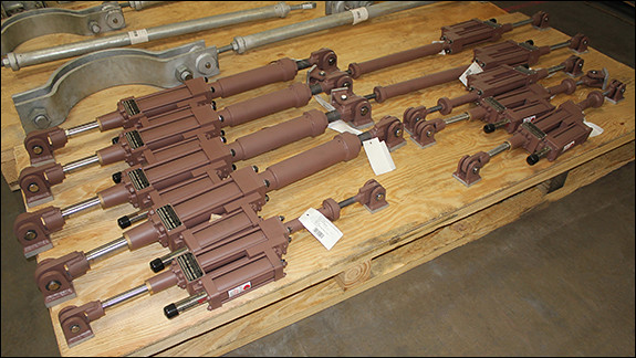
Hydraulic Snubber: A hydraulic cylinder or rotating vane device used for the control of shock or sway in piping systems, while allowing for normal thermal expansion. (See Product)
Hydrostatic Lock: See Travel Stop.
Hydrostatic Test: A pre-operational test, whereby the piping system is subjected to a pressurized fluid test in excess of the operational pressure to assure the integrity of the system. (See Test)
Hydrostatic Test Load: A temporary loading condition consisting of a total of the gravitational piping, insulation and test fluid weights for piping systems subject to hydrostatic tests. (See Test)
Insert: A device, embedded in concrete, to which a Pipe Hanger Assembly can be attached.
Insert Nut: A female threaded device which locks into position in an Insert and receives a threaded Hanger Rod.
Instrument Supports: Devices fabricated from small bore piping used to support process instrumentation such as temperature sensors, flow meters, etc. (See Product)
Jacket: A non-load bearing metal covering placed around the insulation to protect it against damage.
Kneebrace: A diagonal structural member used to transfer load or provide stability.
Light Bracket: A Bracket used for the support of light loads.
Limit Stop: An internal device built into a Variable Spring or Constant Support Hanger to prevent the overstressing of the spring coil, over-travel, or release of the load.
Liner: Material placed between pipe and pipe attachment to protect piping from damage or other undesirable effects.
Load Adjustment Scale: A scale used on a Constant Support Hanger to indicate the load adjustment.
Load Bolt or Pin: A bolt or pin which is used to support the weight being carried by the Pipe Hanger Assembly; e.g. the top pin or bolt in a Three Bolt Pipe Clamp.
Load Coupling: An Adjustment Device used to connect the Hanger Rod to a Variable Spring Hanger or Constant Support Hanger.
Load Indicator: The load plate or other means used to indicate the reading on the Load Scale of a Variable Spring Hanger.
Load Scale: A scale attached to a Variable Spring Hanger to provide a means of indicating the supported load.
Load Variation: A term associated with Variable Spring Hangers used to describe the difference in supporting effect between the hot and cold elevations of the support point.
Mark Number: A unique number used to identify pipe hangers.
Mechanical Snubber: A mechanical device used for the control of shock or sway in piping systems, while allowing for normal thermal expansion. (See Product)
Medium Bracket: A Bracket used for the support of moderate loads.
Multiple Support: A Pipe Hanger Assembly consisting of a common cross member used to support parallel run or banks of piping.
Non-Metallic Wear Pad: A sacrificial plate used to prevent damage to the pipe by absorbing the frictional load caused by the movement of pipe on structural steel. (See Product)
Offset: A relative displacement between the Structural Attachment and Pipe Attachment, which may be incorporated into the design of the Pipe Hanger Assembly to accommodate the piping movement.
Pipe Attachment: Any device used to connect the pipe to the remainder of the Pipe Hanger Assembly.
Pipe Clamp: A bolted Pipe Attachment which clamps around the pipe to connect the pipe to the remainder of a Pipe Hanger Assembly. (See Product)
Pipe Clip: A Pipe Attachment used to hold the pipe directly to a structure, also referred to as a strap or pipe strap.
Pipe Covering Protection Saddle: A device used to prevent damage to the insulation at the support point. (See Product)
Pipe Hanger: A device which is suspended from a structure and is used to carry the piping load in tension.
Pipe Hanger Assembly: A general term used to describe a series of assembled components which make up a Pipe Hanger, Pipe Support, Restraint, Anchor, Guide, etc.
Pipe Hanger Cold Load: Loading at ambient temperature, resulting from the use of Variable Spring Hangers in the support of a piping system. The cold load equals the operating load plus or minus the Load Variation.
Pipe Hanger Cold Spring Load: An additional force that may occur at a support point as a result of the Cold Spring of a piping system.
Pipe Hanger Deadweight Load: Loading condition which considers only the dead weight of the piping, insulation, and contents.
Pipe Hanger Design Load: The combination of operating and other loads as defined by job specification.
Pipe Hanger Friction Load: Loading as a result of frictional forces due to sliding surfaces.
Pipe Hanger Hot Load: Operating load on a Variable Spring Hanger (normally represents deadweight under operating conditions.)
Pipe Hanger Seismic Load: Temporary loading associated with the occurrence of an earthquake.
Pipe Hanger Thermal Load: Loading introduced by the restraint of a piping system against thermal expansion or contraction.
Pipe Hanger Water Hammer Load: Temporary loading resulting from a change in the flow rate of the piping contents.
Pipe Roll: A roller device used to support horizontal piping and provide for axial movement.
Pipe Saddle Supports: A Stanchion utilizing a curved section for cradling the pipe. (See Product)
Pipe Shoe: Normally a Tee section attached to the pipe to transmit the load or forces to the adjacent structure. (See Product)
Pipe Slide: A device consisting of a Pipe Attachment and a Slide Plate, to accommodate horizontal pipe movement.
Pipe Support: A device by which piping is carried from beneath and is used to carry the piping weight in compression.
Plate Lug: An attachment welded to a structural member or piping, to provide for a pinned or bolted connection to the remainder of a Pipe Hanger Assembly.
Protection Saddle: See Pipe Covering Protection Saddle. (See Product)
Protection Shield: A metal shield used to maintain the integrity of the Vapor Barrier and/or protect the insulation at support locations. (See Product)
Restraint: Any device which prevents, resists or limits the free movement of the piping.
Restraining Control Device: Any hydraulic, mechanical, spring, or rigid device used for the control of shock and sway in piping systems.
Rigid Hanger: A Pipe Hanger which does not permit vertical movement.
Rigid Support: A Pipe Support which does not permit vertical movement.
Riser: Any vertical portion of a piping system.
Riser Clamp: A Pipe Clamp for the support of vertical piping having separate Load Bolts, to transfer the piping load to the remainder of the Pipe Hanger Assembly. (See Product)
Rod Coupling: A tapped device used to join two threaded rods.
Rod Hanger: An adjustable vertical assembly consisting of a Structural Attachment, Hanger Rod (with or without intermediate components), and Pipe Attachments. (See Product)
Roll Stand: A pipe roller mounted in a stand, used to support horizontal piping from beneath and providing for axial movement.
Roll and Plate: A pipe roller and bearing plate used for minimal axial movement where no vertical adjustment is necessary.
Roll Hanger: A Pipe Attachment which utilizes a pipe roller for axial movement and is used in a Suspension Hanger.
Roll Plate: A flat device which provides a bearing surface for a pipe roll.
Saddle: See Pipe Covering Protection Saddle. (See Product)
Semi-Engineered Hanger Assembly: A Pipe Hanger Assembly which has been indicated on a piping drawing and has been designated as a specific type; i.e. rigid, spring, etc. with Spring Hangers indicating load, movement, spring type and size. This hanger assembly is field fabricated utilizing Bulk Material where applicable.
Shear Lug: A welded Pipe Attachment subjected primarily to shear stress, transferring axial pipe load to the supporting member.
Shield: See Protection Shield.
Side Beam Bracket: A Bracket provided with a hole in the vertical leg for bolting to the building structure and a hole in the horizontal leg to receive a threaded Hanger Rod.
Side Beam Clamp: A Beam Clamp that attaches to a flange of an I-beam or wide flange beam and provides an off-center attachment for the remainder of a Pipe Hanger Assembly.
Single Pipe Roll: A Pipe Attachment which utilizes a Pipe Roll for axial movement and is used in a Trapeze Hanger or Support.
Sleeper: A horizontal beam, usually located at grade, upon which horizontal pipe runs are supported.
Slide Plate: A flat plate whose surface has been prepared in a manner which will facilitate a sliding motion. (See Product)
Sliding Support: A device providing support from beneath by offering no resistance, other than frictional, to horizontal movement.
Snubber: A hydraulic, mechanical, or spring device used for the control of shock and sway in piping systems. (See Product)
Spider Guide: A Pipe Attachment for insulated piping used for maintaining alignment of piping through its axial expansion and contraction cycles. (See Product)
Split Ring: A Pipe Clamp used on non-insulated piping, provided with a hinge which permits installation before or after the piping is in place.
Spring Cushion Hanger: A simple, non-calibrated, single rod spring support, used for providing a cushioning effect.
Spring Cushion Roll: A pair of spring coils with retainers, for use with a Single Pipe Roll.
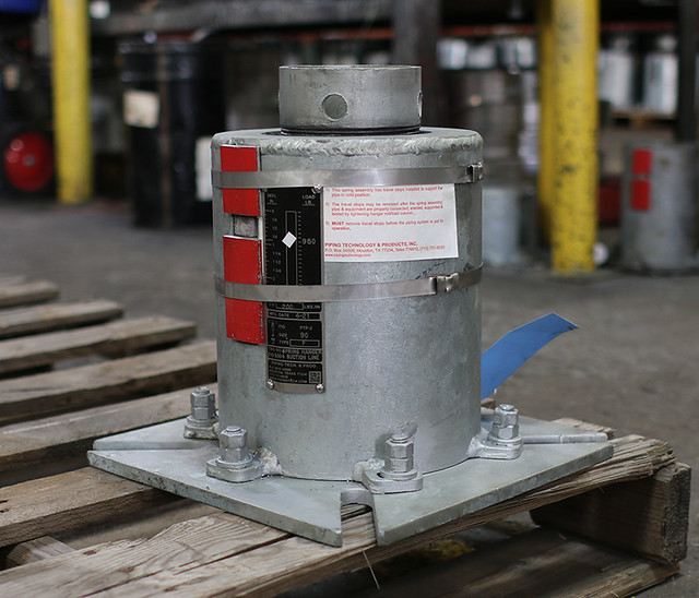
Spring Hanger: A Pipe Hanger, using a spring or springs, to permit vertical movement in a piping system. (See Product)
Spring Snubber: See Spring Sway Brace. (See Product)
Spring Sway Brace: A spring device used for the control of vibration or shock, or bracing against sway in piping systems. (See Product)
Stanchion: A Pipe Support using a vertical member in compression.
Steel Clevis: A forged or fabricated device used to fit over a welding lug in the attachment of a pipe to a structural support. (See Product)
Stop: A device used to limit pipe movement in a specific direction.
Structural Attachment: A device used to connect the remainder of the Pipe Hanger Assembly to the structure.
Strut: A rigid tension/compression member. (See Product)
Sway Brace: See Restraint Control Device. (See Product)
Swivel Turnbuckle: A device which provides flexibility at the pipe connection, in addition to linear adjustment for Suspension Hanger.
Three Bolt Pipe Clamp: A Pipe Clamp normally used for horizontal insulated piping, which utilizes clamping bolts to attach the clamp to the pipe and a separate Load Bolt to transfer the piping weight to the remainder of the Pipe Hanger Assembly from a point outside the insulation. (See Product)
Top Beam Clamp: A Beam Clamp which attaches to the top of a structural beam and provides an attachment to the remainder of the Pipe Hanger Assembly from the side of the beam.
Trapeze Hanger: A Pipe Hanger consisting of parallel vertical rods which are suspended from a structure and connected at their lower ends by a horizontal member from which the pipe is supported. Some of its uses are for clearing overhead obstructions or where insufficient vertical space is available to accommodate a single Suspension Hanger.
Travel Indicator: For Constant Support Hangers, a device attached to a moveable arm of a Constant Support Hanger, used to indicate the reading on the Travel Scale in order to show the vertical pipe movement. For Variable Spring Hangers, the spring load plate which indicates the reading on the Load/Travel scale in order to show the vertical pipe movement.
Travel Scale: A device attached to a spring unit, whose purpose is to provide for an indication of the vertical pipe movement.
Travel Stop: A device which temporarily locks the moveable parts of a Spring Hanger in a fixed position, enabling a load to be transferred through the Spring Hanger to the supporting structure while maintaining the piping at a desired elevation during erection and/or Hydrostatic Testing.
Turnbuckle: A device with one left-hand female threaded end and one right-hand female threaded end, used to join two threaded rods and provide linear adjustment. (See Product)
U-Bolt: A U-shaped rod with threaded ends, that fits around a pipe and is attached to a supporting member. (See Product)
Vapor Barrier: An uninterrupted covering for an insulated pipe to preclude the introduction of moisture into the insulation.
Variability: The Load Variation of a Variable Spring Hanger divided by the Hot Load expressed as a percentage.
Variable Spring Hanger: A spring coil device which produces a varying supporting effect while permitting vertical pipe movement. (See Product)
Welded Beam Attachment: A u-shaped flat bar device, normally welded to a steel beam used to connect the remainder of a Pipe Hanger Assembly. (See Product)
Welded Pipe Attachment: A Pipe Attachment which requires welding to the pipe in order to connect the pipe to the remainder of the Pipe Hanger Assembly. (See Product)
Welding Lug: A steel device that is welded to supports or structural steel to allow for the suspension of pipe using rod hangers. (See Product)
Weldless Eye Nut: A forged steel device which provides for the attachment of a threaded Hanger Rod to a bolt or pin connection. (See Product)
Wide Flange Beam Clamp with Links: A steel Beam Clamp for the suspension of pipe loads from structural beams.
Yoke U-Bolt: A type of clamp that includes a u-shaped rod with threaded ends, that fits around a pipe and is recommended for the suspension of high-temperature piping. (See Product)