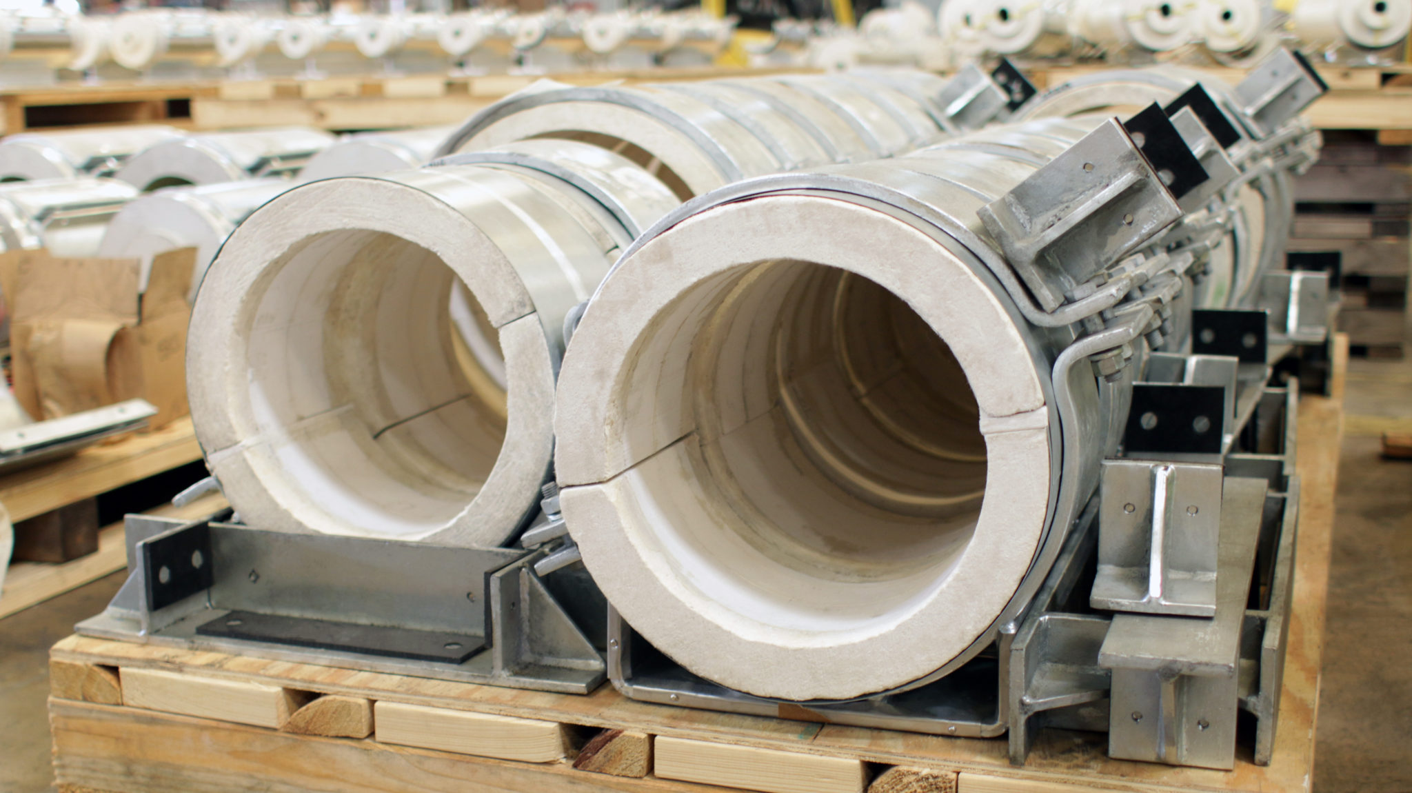
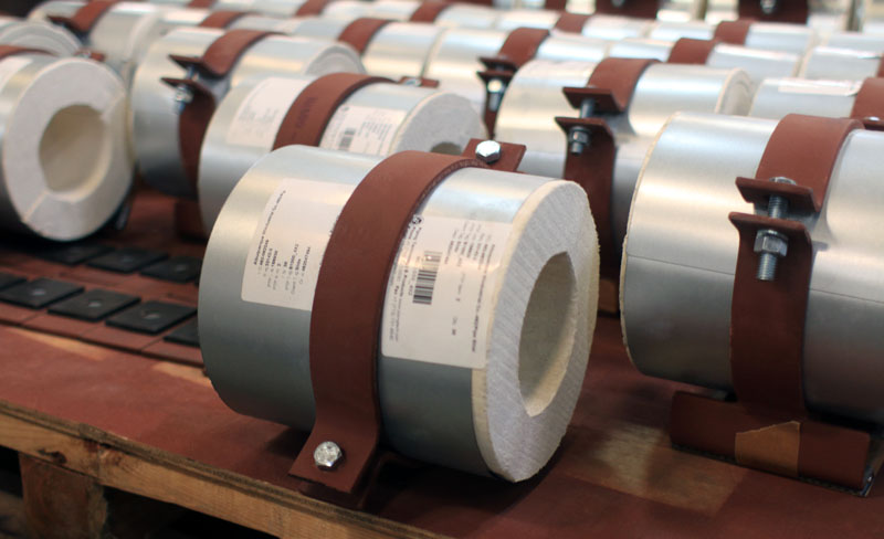
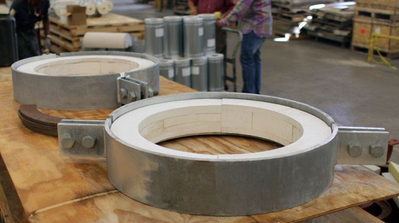
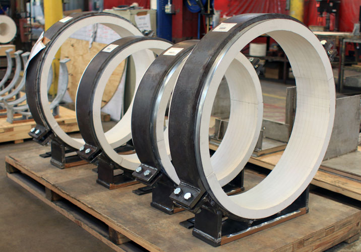
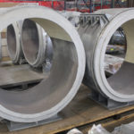
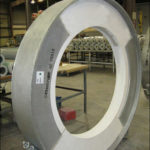
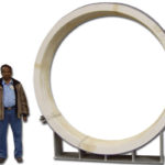
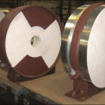
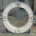
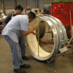
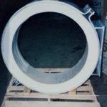
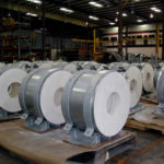
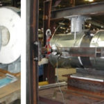
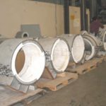
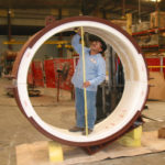
High Temperature Supports (Hot Shoes) (HS-1000 – HS-6060)
A hot shoe is a pipe support used for high temperature applications, such as high pressure steam lines or boiler feed water, where heat loss through the pipe support is not desirable. These supports can be used for temperatures up to 1400˚ Fahrenheit.
Ammonia Plant
Bioengergy Plant
Chemical Plant
Clean Fuels
Cogeneration Plant
Cold / Cryogenic Service
Commercial
Electric Plant
Energy Facility
Ethylene Plant
Fluid Processing Plant
Granular Activated Carbon Mnfr Plant
Hospital
Light Hydrocarbon Production Facility
LLDPE Chemical Plant
See More
Download Pre-Insulated Pipe Supports General Information
Scope
This specification covers the requirements for the design, fabrication and use of our pre-insulated low temperature pipe supports. These supports are for pipes having surface temperature ranges of –10oF (-23oC) to 1200oF (650oC).
General Requirements
• All insulated pipes shall be supported with pre-insulated pipe supports.
• Insulated pipe supports shall comply with the following standards:
A. ANSI/ASME B31.1 & B31.3
B. Manufacturers Standardization Society SP-58, 69, & 89.
• The following criteria shall be considered in the selection of low-temperature pre-insulated pipe supports:
A. Vertical, lateral and axial support design load limits.
B. Vertical, lateral, and axial support design travel limits.
C. The temperature of the cryogenic pipe support, at the pipe surface, and ambient conditions.
D. All test or pre-operational loads that may exceed normal operating conditions.
E. Any dimensional clearances needed during installation and operation should be specified.
F. Material for any items that will be welded directly to the pipe.
G. All loading and displacements caused by seismic, hydraulic surge, or other disturbances.
H. The temperature at the support steel.
• Upon request by the purchaser or the end user, design calculations of supports will be made available for review.
• Upon request by the purchaser or the end user, localized stress calculations for lugs and other welded attachments will be made available for review.
• Prior to placing an order, all special requirements such as mill test reports, material certification or non-standard materials must be specified.
Design Criteria
• The load bearing insulating materials used in the pre-insulated pipe support shall be the same material that was used to rate the support.
• At the request of the end user or the purchaser, we will make available compressive strength and thermal conductivity testing results of the high-density polyurethane in the format provided by MSS SP-89. Testing will be done at the maximum temperature of 1200.
• A description of the quantity of load that can be applied to the support shall be provided for evaluation upon request. A minimum safety factor of 5 at the system design temperature shall be used to determine the maximum load.
• Testing for compressive strength properties shall comply with ASTM D1621, the standard testing method, for compressive properties of Rigid Cellular Plastics.
• Testing for thermal conductivity shall comply with ASTM C165, Standard Test Method of Measuring Compressive Properties for Thermal Insulation.
• Load bearing element capacity shall be demonstrated at the system design temperature and load.
• The pre-insulated pipe support assembly shall exert enough clamping force to assure that the support will move axially with the pipe and will not slip when under design conditions.
• All slide plate surfaces shall be designed so that the coefficient of friction will be limited to .1 for the design life without requiring lubrication. Any friction reducing material that requires bonding shall be bonded to a backing structure prior to shipment.
• The lower design temperature of the unit at the pipe surface shall be –10oF (-23oC). The maximum outside design temperature should be 200oF (93oC), the maximum pipe surface temperature should be 1200oF (650oC). For higher or lower temperatures, please contact us.
• The required properties of the load bearing insulating materials under design conditions are:
A. The maximum thermal conductivity is 1.2 BTU-in/hr-ft2 – oF at a mean insulation temperature of 700oF.
B. There can be a maximum of 1/32″ of non-permanent deformation under the pipe due to the permanent consolidation of the load bearing insulation.
C. There can be an additional 1/32″ of non-permanent deformation under the pipe.
• The outside surface temperature of the unit shall not exceed 120oF when ambient air is 70oC.
Fabrication
• All polyurethane foam shall be monolithic and molded oversized so that excess material shall be removed by cutting to achieve the final finished dimensions, the outer skin shall be removed.
• The pre-insulated pipe support shall:
A. Come pre-assembled with sufficient insulation extending past the outer metal jacket, allowing the pipe insulator to butt the line insulation against it.
B. Will withstand the clamping forces transferred by the cradle.
C. Will be treated to prevent moisture degradation in accordance with ASTM C656 Type I.
D. The ID and OD dimensions of the insulation shall conform to ASTM specification C585 unless otherwise specified.
• Designs having sliding surfaces shall incorporate two slide plates at each surface. Each slide plate will be made of 3/32″ thick glass filled reinforced PTFE, 25% glass filled, bonded to a 10GA carbon steel backing plate. The PTFE, 25% glass filled, will be recessed ¼” from the edge of the plate.
• All welding shall comply with B31.3 and B31.1 Piping Code and AWS D1.1
• The following items unless otherwise noted on contract drawings shall be in accordance with the following:
A. Structure shapes and plate: ASTM A-36
B. Bolts and studs: ASTM A-307
C. Nuts: A563
Size Range: For use with 1/2″ through 72″, most designs. insulation thickness of 1″. 1-1/2″, 2″, 2-1/2″, 3″, 3-1/2″, 4″ and larger sizes where specified.
How to Size: Refer to “Insulation Chart” below for Sizing the Insulation Material.
Ordering: Specify figure number, pipe size, insulation thickness, and insulating material
Example:
Fig. 4700-4-3-B
• 4700 = Type of Insulated Shoe (cold)
• 4 = Nominal Pipe Size
• 3= Insulation Thickness
• B = Insulation Material (Micarta)
| NOMINAL INSULATION THICKNESS (in.) | INSULATION O.D. (in.) | APPROX. INSULATION THICKNESS (in.) |
Pipe size: 1/2" (O.840 O.D.) |
||
| 1 | 2 7/8 | 1 |
| 1 1/2 | 4 | 1 9/16 |
| 2 | 5 | 2 1/16 |
| 2 1/2 | 6 5/8 | 2 7/8 |
| 3 | 7 5/8 | 3 3/8 |
| 3 1/2 | 8 5/8 | 3 7/8 |
| 4 | 9 5/8 | 4 3/8 |
Pipe size: 3/4" (1.050 O.D.) |
||
| 1 | 2 7/8 | 7/8 |
| 1 1/2 | 4 | 1 7/16 |
| 2 | 5 | 1 15/16 |
| 2 1/2 | 6 5/8 | 2 3/4 |
| 3 | 7 5/8 | 3 1/4 |
| 3 1/2 | 8 5/8 | 3 3/4 |
| 4 | 9 5/8 | 4 1/4 |
Pipe size: 1" (1.315 O.D.) |
||
| 1 | 3 1/2 | 1 1/16 |
| 1 1/2 | 4 1/2 | 1 9/16 |
| 2 | 5 9/16 | 2 1/8 |
| 2 1/2 | 6 5/8 | 2 5/8 |
| 3 | 7 5/8 | 3 1/8 |
| 3 1/2 | 8 5/8 | 3 5/8 |
| 4 | 9 5/8 | 4 1/8 |
Pipe size: 1 1/4" (1.66 O.D.) |
||
| 1 | 3 1/2 | 15/16 |
| 1 1/2 | 5 | 1 11/16 |
| 2 | 5 9/16 | 1 15/16 |
| 2 1/2 | 6 5/8 | 2 1/2 |
| 3 | 7 5/8 | 3 |
| 3 1/2 | 8 5/8 | 3 1/2 |
| 4 | 9 5/8 | 4 |
Pipe size: 1 1/2" (1.90 O.D.) |
||
| 1 | 4 | 1 1/16 |
| 1 1/2 | 5 | 1 9/16 |
| 2 | 6 5/8 | 2 3/8 |
| 2 1/2 | 7 5/8 | 2 7/8 |
| 3 | 8 5/8 | 3 3/8 |
| 3 1/2 | 9 5/8 | 3 7/8 |
| 4 | 10 3/4 | 4 7/16 |
Pipe size: 2" (2 3/8" O.D.) |
||
| 1 | 4 1/2 | 1 1/16 |
| 1 1/2 | 5 9/16 | 1 9/16 |
| 2 | 6 5/8 | 2 1/8 |
| 2 1/2 | 7 5/8 | 2 5/8 |
| 3 | 8 5/8 | 3 1/8 |
| 3 1/2 | 9 5/8 | 3 5/8 |
| 4 | 10 3/4 | 4 3/16 |
Pipe size: 2 1/2" (2 7/8" O.D.) |
||
| 1 | 5 | 1 1/16 |
| 1 1/2 | 6 5/8 | 1 7/8 |
| 2 | 7 5/8 | 2 3/8 |
| 2 1/2 | 8 5/8 | 2 7/8 |
| 3 | 9 5/8 | 3 3/8 |
| 3 1/2 | 10 3/4 | 3 15/16 |
| 4 | 11 3/4 | 4 7/16 |
Pipe size: 3" (3 1/2" O.D.) |
||
| 1 | 5 9/16 | 1 |
| 1 1/2 | 6 5/8 | 1 9/16 |
| 2 | 7 5/8 | 2 1/16 |
| 2 1/2 | 8 5/8 | 2 9/16 |
| 3 | 9 5/8 | 3 1/16 |
| 3 1/2 | 10 3/4 | 3 5/8 |
| 4 | 11 3/4 | 4 1/8 |
Pipe size: 3 1/2" (4" O.D.) |
||
| 1 | 6 5/8 | 1 5/16 |
| 1 1/2 | 7 5/8 | 1 13/16 |
| 2 | 8 5/8 | 2 5/16 |
| 2 1/2 | 9 5/8 | 2 13/16 |
| 3 | 10 3/4 | 3 3/8 |
| 3 1/2 | 11 3/4 | 3 7/8 |
| 4 | 12 3/4 | 4 3/8 |
Pipe size: 4" (4 1/2" O.D.) |
||
| 1 | 6 5/8 | 1 1/16 |
| 1 1/2 | 7 5/8 | 1 9/16 |
| 2 | 8 5/8 | 2 1/16 |
| 2 1/2 | 9 5/8 | 2 9/16 |
| 3 | 10 3/4 | 3 1/8 |
| 3 1/2 | 11 3/4 | 3 5/8 |
| 4 | 12 3/4 | 4 1/8 |
Pipe size: 4 1/2" (5" O.D.) |
||
| 1 | 7 5/8 | 1 5/16 |
| 1 1/2 | 8 5/8 | 1 13/16 |
| 2 | 9 5/8 | 2 5/16 |
| 2 1/2 | 10 3/4 | 2 7/8 |
| 3 | 11 3/4 | 3 3/8 |
| 3 1/2 | 12 3/4 | 3 7/8 |
| 4 | 14 | 4 1/2 |
Pipe size: 5" (5 9/16" O.D.) |
||
| 1 | 7 5/8 | 1 |
| 1 1/2 | 8 5/8 | 1 1/2 |
| 2 | 9 5/8 | 2 |
| 2 1/2 | 10 3/4 | 2 9/16 |
| 3 | 11 3/4 | 3 1/16 |
| 3 1/2 | 12 3/4 | 3 9/16 |
| 4 | 14 | 4 3/16 |
Pipe size: 6" (6 5/8" O.D.) |
||
| 1 | 8 5/8 | 15/16 |
| 1 1/2 | 9 5/8 | 1 7/16 |
| 2 | 10 3/4 | 2 |
| 2 1/2 | 11 3/4 | 2 1/2 |
| 3 | 12 3/4 | 3 |
| 3 1/2 | 14 | 3 5/8 |
| 4 | 15 | 4 1/8 |
Pipe size: 7" (7 5/8" O.D.) |
||
| 1 | 9 5/8 | 1 |
| 1 1/2 | 10 3/4 | 1 1/2 |
| 2 | 11 3/4 | 2 |
| 2 1/2 | 12 3/4 | 2 1/2 |
| 3 | 14 | 3 1/8 |
| 3 1/2 | 15 | 3 5/8 |
| 4 | 16 | 4 1/8 |
Pipe size: 8" (8 5/8" O.D.) |
||
| 1 | 10 3/4 | 1 1/16 |
| 1 1/2 | 11 3/4 | 1 1/2 |
| 2 | 12 3/4 | 2 |
| 2 1/2 | 14 | 2 5/8 |
| 3 | 15 | 3 1/8 |
| 3 1/2 | 16 | 3 5/8 |
| 4 | 17 | 4 1/8 |
Pipe size: 9" (9 5/8" O.D.) |
||
| 1 | 11 3/4 | 1 1/16 |
| 1 1/2 | 12 3/4 | 1 1/2 |
| 2 | 14 | 2 |
| 2 1/2 | 15 | 2 5/8 |
| 3 | 16 | 3 1/8 |
| 3 1/2 | 17 | 3 5/8 |
| 4 | 18 | 4 1/8 |
Pipe size: 10" (10 3/4" O.D.) |
||
| 1 | 12 3/4 | 1 |
| 1 1/2 | 14 | 1 9/16 |
| 2 | 15 | 2 1/16 |
| 2 1/2 | 16 | 2 9/16 |
| 3 | 17 | 3 1/16 |
| 3 1/2 | 18 | 3 9/16 |
| 4 | 19 | 4 1/16 |
Pipe size: 11" (11 3/4" O.D.) |
||
| 1 | 14 | 1 1/8 |
| 1 1/2 | 15 | 1 9/16 |
| 2 | 16 | 2 1/16 |
| 2 1/2 | 17 | 2 9/16 |
| 3 | 18 | 3 1/16 |
| 3 1/2 | 19 | 3 9/16 |
| 4 | 20 | 4 1/16 |
Pipe size: 12" (12 3/4" O.D.) |
||
| 1 | 15 | 1 1/8 |
| 1 1/2 | 16 | 1 9/16 |
| 2 | 17 | 2 1/16 |
| 2 1/2 | 18 | 2 9/16 |
| 3 | 19 | 3 1/16 |
| 3 1/2 | 20 | 3 9/16 |
| 4 | 21 | 4 1/16 |
Pipe size: 14" (14" O.D.) |
||
| 1 | 16 | 2 |
| 1 1/2 | 17 | 1 7/16 |
| 2 | 18 | 1 15/16 |
| 2 1/2 | 19 | 2 7/16 |
| 3 | 20 | 2 15/16 |
| 3 1/2 | 21 | 3 7/16 |
| 4 | 22 | 3 15/16 |
| Large sizes, insulation O.D. are in 1" increments. Insulation thicknesses through 36" same as nominal. All dimensions rounded to the nearest 1/16". |
||

