Tag: technical bulletins
Pressure Balanced Expansion Joints
Engineered Spring Supports: Big Ton Spring Supports
“Big Ton” is the name PT&P uses for a special type of variable spring supports which was developed for the petrochemical industry. Many of these supports have been in service for more than twenty years. These supports are very stable and can be designed to supports loads up to 200,000 pounds. A typical Big Ton will have a rectangular array of coil springs supporting a pressure plate which in turn support a top load flange. Slide plates are used when required.
Big Tons provide the designer with options that are not available with typical spring supports because they can support vessels and other components which have piping attached to them. The piping designer can choose to support these components and thus reduce loads which would be transferred to the piping. This is often a more economical and stable design for entire systems.
A recent example of this occurred during the design of a major new additions to a refinery in Korea. The original design called for a number of large constant spring hangers to support the piping. PT&P engineers showed our customer how to use Big Ton supports for certain units and eliminate the need for constant supports for the piping. This reduced the cost of the support system and also provided a more reliable total system.
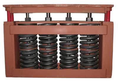
A custom big ton
The illustration below shows a Big Ton with nine springs set within an efficiently compacted structure. The table below is a Bill of Material for this unit. Notice the many components that go into making a Big Ton. All Big Tons are in rectangular configurations. Some Big Tons, because of spatial restraints, are designed in one row, as shown in Fig. 1. This tends to make for longer units. If the width is not of great concern and length is, then Big Tons can be designed with more than one row as shown in Fig. 2.
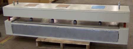
A long custom big ton with slide plates.
If you have a particular application to discuss, you will need the same type of information required for other spring supports such as, loads, travel, distances, and directions. If you are interested in learning more about Big Tons, please contact us. Please refer to Sizing a Variable Spring Support if you need help on sizing Big Ton Springs.
Variable Spring Supports vs Constant Spring Supports
By Dr. Hyder Husain Ph.D.
Dec. 2, 2010
What is the difference between a variable & a constant spring support? In a variable support, the force acting on the spring and hence the reactive force varies during the pipe travel, while the moment about the line of action is zero. In contrast, in a constant support, the fixed applied load remains uniform throughout its travel but the moment around a pivot point varies.
What is a variable support? A variable support is essentially a spring, or series of springs, in a container. When the installed load “w” is applied, the spring is compressed through the distance W/k (where k is the spring rate) such that the reactive force exerted by the spring is also “w” under the equilibrium condition. As the pipe moves due to thermal expansion, it produces a deflection (∆L), causing a differential load (∆W=k ● ∆L), to act on the spring(s). Depending upon the direction of the movement, the change in load (∆W) will either add to or subtract from our installed load “w” to reach our final operating load (w1). In order to minimize the stress variations, the differential load (∆W) for a given variable spring support is limited to a maximum of 25% percent of the operating load (w1).
What is a constant support? A constant support is a device comprised of a spring or series of springs and an integral cam mechanism. The external load of a constant support is fixed while its moment about the fixed pivot point varies during its travel (because the moment arm length changes). In order to maintain an equilibrium condition, the external force moment is balanced by the internal moment produced due to the spring’s compression or decompression about the pivot during the displacement of the pipe.
With an appropriate choice of moment arms, as developed by the cam geometry, and spring properties (i.e. spring rate), a resisting force can be provided that is nearly independent of position during its travel.
At each travel location of the applied load, the moment caused by the external load is balanced by the counter moment produced by the (compressed/decompressed) spring force with the appropriate moment arm. Typically, the variation of the active and reactive forces is very small (with a maximum deviation of 6%) and can be taken as a constant force while moving either upward or downward.
Safety Alert for Installation of Spring Supports
|
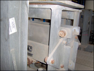
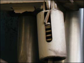
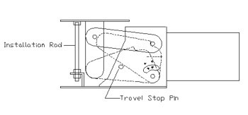
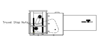
PT&P received an emergency phone call from a petrochemical plant in the Persian Gulf. There was a ½” gap between the load flange of the Constant Spring support and the Trunion of the process line while the plant was in operation (Fig 1). Our expert field engineer was immediately dispatched to the client site to investigate the issue. An inspection of the products in question revealed that the travel stop nuts were bolted down. This prevented the support table from moving and supporting the pipe (fig 2).
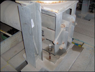 Figure 2 |
|
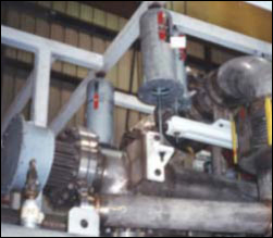
Travel Stop Removal is one of the most important tasks that must to be done when installing a spring support. Travel stops should be removed after Hydro testing when the pipeline is at the “Cold Load.” When the stops are left in place, “piping loads” are transferred to the piping system instead of being absorbed by the springs. Some of the results of this are: • Damage to pump equipment In 30 – 40% of the plants that PT&P visits for site inspection or hanger maintenance issues, there is at least one spring hanger with the stops in place. (Fig 3) The possible reasons for this are: • Improper Installation
The following procedures should be followed when installing spring cans. These can be used for either Variable Load supports or Constant Load Hangers which are supported from the top. Bottom supported constants are discussed below. 1. Attach upper attachment(s). For more detailed instructions please see our installation and maintenance guides: For F-type Constants (Fig 5.) 1. Secure base plate of the constant to the supporting structure.
For U type Constants (Fig 6.) 1. Attach base plate to supporting structure
It is also important not dispose of the travel stops once the springs are installed. They will be useful during scheduled maintenance. Anytime that you are going to open up a pipeline with springs on it, you should replace the travel stops. It We offer: • Site inspection – inspection of existing supports to determine their condition and recommend other changes. PT&P can and has worked in many places around the US and the World; we have over 30 years of experience in the pipe support industry. We are confident in our ability meet any challenge that comes our way. |
Slide Plate Applications
By Jerry Godina
January 26, 2011
Slide plates are designed to provide a low coefficient of friction between stationary structures and 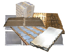 moving pipe supports. The plates provide a surface friction that has been carefully designed to provide for movements of the piping systems, due to factors such as thermal expansion. In this way, the slide plates allow the system to move with less force, keeping it in proper working order.
Assembly Basics
Slide plates are usually arranged in what is known as a ‘sandwich’ formation, which consists of an upper slide plate component and a lower slide plate component.
The lower slide plate may also be welded to a stationary support (i.e. structural steel member), which grounds the plate, while the other plate is attached to the moving component directly. As the system moves, friction is transferred at the intersection of the two plates.
When ordering, always specify the dimensions of the upper and lower slide plate. As a rule, the upper slide plate should be large enough to completely cover the lower plate at all times.
Recommended Applications / Temperature Limits
The recommended applications temperature limit is negative 320 fahrenheit to positive 500 fahrenheit with a low pressure load (PSI)
Different plates are suited for different temperature limits. While all plates have been rigorously tested for suitability within industrial settings, understanding the particular variables of that setting is vital to purchasing the appropriate plate for each application.
PTFE, 25% Glass Filled Slide Plates
These slide plates will handle temperatures from negative 320 degrees Fahrenheit to positive 500 degrees Fahrenheit.
The PTFE plates are ideal for cross beam and girder slip joints, air preheaters, penstocks, vessels, and other industrial and architectural applications.
Installation of PTFE plates is available in two configurations, the standard and custom. The standard assembly features two sets of 3/32” thick PTFE pads bonded to 1/8” carbon steel backing plates with a 1/2” lip for field welding. The custom assembly features 2 sets of 3/32” thick PTFE pads bonded to the specified backing material, with a minimum 1/2” lip for full welding. If the desired thickness of the backing plate is not the standard 1/8,” those who are purchasing the plate should specify a different thickness when placing their order
Bronzphite® Slide Plates
-320F to +1100F with 5000 PSI
Bronze plates impregnated with graphite will also handle temperatures up to positive 1100 degrees Fahrenheit. Additionally, bronze plates are suited for high pressure systems with a load of up to 5000 PSI.
The bronze plate is available in a standard configuration, which consists of the bronze plate bolted to a steel backing plate, allowing it to be welded in the field. The plate is self-lubricating and durable, and is recommended for a variety of industrial applications, including pipelines, storage tanks, and dust collectors.
Graphite Slide Plates
Up to 1,000˚ F with 2000 PSI
For those systems which produce exceptional pressure and heat, pure graphite slide plates are recommended. With a range of up to 1,000 degrees Fahrenheit for ambient conditions, and 3,000 degrees Fahrenheit for inert settings, graphite slide plates can also handle up to 2000 PSI. The graphite plates come in two different configurations, the ‘bonded’ and ‘bolted’ assembly. The bonded configuration consists of a ¼” thick graphite pad bonded to a metal backing plate. The bolted configuration consists of a ½” thick graphite pad bonded and bolted to a metallic backing pad. Both configurations can either be tack welded or fully welded to support components.
Graphite plates are best for heavy infrastructures such as bridges, highway overpasses, railroad bridges, and airport hangar doors. Domes, roof slabs and corbels, vibration pads and other architectural features are also suitable applications. In the industrial realm, offshore drilling rigs, wind tunnels, and other heavy machinery benefit from graphite plates.
Marinite Slide Plate
Marinite can be used as the insulating material in hot piping supports. The most widely known grade for Marinite is grade P. Marinite-P is most often used as structural insulation because of its high dimensional stability. Marinite-P is incombustible, provides high insulation values, and high compressive strengths and is thus appropriate in high-load and high-temperature applications. The material minimizes decay, rust, and corrosion and it resists damage during installation and provides durable service. The material acts as a suitable insulator in fireproofing and heat processing equipment applications up to 1200°F (649°C).
History of Insulated Pipe Supports
By David Smith
December 17, 2010
In many chemical plants, refineries 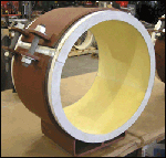 and LNG facilities, there are processes where the “product” inside the piping is at very cold temperatures (down to -320 degrees F in some processes). In these applications, there exists the need to both support and insulate the pipeline while simultaneously allowing and/or limiting movement. The ability to adequately insulate the pipeline helps to increase the efficiency of the piping system by not allowing the “cold” inside the pipe to escape to the environment. However, at points where both supporting and insulating the pipeline is necessary, a special solution is required. Today, several terms have evolved to classify this type of support, including “Insulated Support”, “Cryogenic Support”, and “Cold Support”. Regardless of the term used to describe insulated supports, they all have the same function: to both support and insulate the piping.
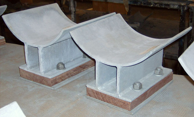
It is still common to see one of the earliest methods used to support cold pipelines in plants today. These first types of cold supports utilized wood, usually oak as the preferred insulation. The oak would be cut to match the curvature of the pipe and be placed beneath the pipe. A steel cradle or other type of support component could then be placed beneath the insulation wood. Although this method was very crude, it served the purpose of insulating the pipe from the “steel pipe rack.”
Later, in order to prevent the decay of the wood, various coatings were applied. One method to protect the wood still in use today is “impregnation” of the wood using various types of resins or plastics. The result of this method yields a wood that is reinforced with plastic which helps to provide resistance to moisture while still maintaining the insulating properties of the wood. These “laminated wood blocks” also provide higher compressive strength (30,000 PSI) and higher tensile strength (15,000 PSI) than using untreated wood.
 |
|
Insulated Pipe Supports with Permali Wood Bases
|
Developments made, during the 1950’s and 1960’s, ushered in the use of chemical compounds to replace previously used natural compounds. “Foam Glass” emerged as an excellent, inexpensive insulator for use on cold pipelines. “Foam Glass” is a lightweight material having a closed-cell structure and is manufactured primarily from recycled glass. It is generally formed in molds that are packed with a mixture of crushed glass and a chemical agent containing carbon. To form the material, heat is applied and the glass grains become soft. The carbon gives off a “gas” that is entrapped in the glass and forms the closed-cell structure. Because it is a great insulator, however, it can be utilized in those portions of the insulated support that are not supporting the load. Because the compressive strength of “Foam Glass” is very low (400 PSI), it is not used in load bearing applications.
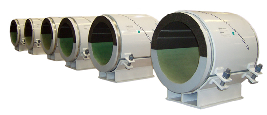
Another chemical compound developed during this same time period is Polyurethane. Although not as good an insulator as Foam Glass, polyurethane does provide greater load carrying capabilities due to its higher range of densities. Polyurethane is formed through a “step-growth polymerization” process by involving 1.) a monomer containing at least two isocyanate functional groups with 2.) a second monomer containing at lease two hydroxyl groups in the presence of a catalyst and 3.) a catalyst agent manufactured to be resilient, flexible and durable. Polyurethane is widely used in pipe supports within LNG plants. By varying the densities, polyurethane can be used at different locations to insulate the piping while acting as a vertical, lateral or anchor support. When a protective coating is applied (such as monolar mastic), the material becomes highly resilient to moisture. Additionally, when combined with other additives, polyurethane offers excellent flame-retardant characteristics. Utilized between the steel pipe support components and the pipeline, polyurethane can support the piping in a number of ways. Most applications incorporate multiple 180-degree sections of polyurethane surrounding the pipe with varying lengths, dependent upon the load or weight of the pipe.
 |
|
Insulated Supports Designed with a Combination of Polyurethane Foam and Foam Glass
|
Many of the advancements in the insulated pipe support industry are a direct result of technological advancements and continually changing industrial needs. In the future, it is expected that this same type of collaboration will contribute to further improvements of insulated pipe supports.
Cryogenic Application Testing
Objective
Test Results of the formation of ice on an uninsulated pipe carrying liquid nitrogen
Test Facility
A perspective view of the facility is shown in Figure 1. The test facility consists of a 36” long stainless steel pipe of 4 1/2” OD with 4” ID. The pipe ends are closed by 3/4” x 5 1/2” x 21” plates. The pipe is suspended from top using two pipe clamps.
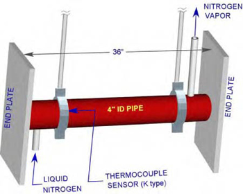
Figure 1: Perspective View of the test facility
To simulate cryogenic condition for an extended period of time, liquid nitrogen from a tank is supplied through a control valve into the pipe at one end and the nitrogen vapor is allowed to escape through a 1/2’’ tube from the other end.
The test facility is set in our workshop area where large size doors allow cross ventilation maintaining atmospheric conditions.
A type “K” thermocouple is set between the pipe and the clamp near the liquid nitrogen inlet to measure the pipe’s outer surface temperature history. Simultaneously, the ambient room temperature, relative humidity, and dew points were measured.
Test Procedure
Liquid nitrogen was allowed to fill completely the stainless steel pipe first, followed by a steady flow of liquid Nitrogen. By adjusting the control valve to a point when the liquid Nitrogen ceases to exit through the vertical outlet tube, the pipe remained completely full of liquid Nitrogen throughout the test. This flow process caused a small fraction of the flowing liquid nitrogen in the pipe to change phase to vapor by gaining latent heat of evaporation from the ambient air and exited through the outlet tube. This maintained almost a constant pipe surface temperature over an extended period of time.
Metering scales were fixed radially outward at three locations (near the two ends and at the middle) along the pipe to measure the ice deposition depth as a function of time.
Results
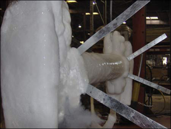
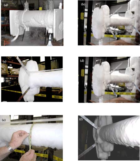
Test results are given in Table 1. After the liquid nitrogen flowed into the pipe, the atmospheric moisture started forming ice on the outer surface of the pipe, end plates and clamps. During this test, the ice thickness varied between day and night. This is due to the daytime temperature being higher than the nighttime temperature.
Material Items
| No. | Date | Time | Pipe Temp | Ambient Temp | Relative | |||
| Humidity | LHS | MID | RHS | |||||
| 1 | 9/14/2006 | 12:00 PM | 84oF | 83oF | 80% | 0 | 0 | 0 |
| 2 | 9/14/2006 | 2:00 PM | -30oF | 83oF | 80% | 0 | 0 | 0 |
| 3 | 9/14/2006 | 6:00 PM | -196oF | 91oF | 75% | 0.5 | 0.5 | 0.5 |
| 4 | 9/15/2006 | 6:00 AM | -299oF | 80oF | 62% | 1.5 | 1.5 | 1.5 |
| 5 | 9/15/2006 | 10:00 AM | -299oF | 80oF | 80% | 1.5 | 1.5 | 1.5 |
| 6 | 9/15/2006 | 2:00 PM | -289oF | 90oF | 50% | 1.25 | 1.25 | 1 |
| 7 | 9/15/2006 | 6:00 PM | -295oF | 93oF | 70% | 1.5 | 1.5 | 1.25 |
| 8 | 9/16/2006 | 6:00 AM | -296oF | 84oF | 80% | 2 | 2 | 1.75 |
| 9 | 9/16/2006 | 10:00 AM | -295oF | 88oF | 80% | 1.5 | 1.5 | 1.5 |
| 10 | 9/16/2006 | 2:00 PM | -294oF | 91oF | 80% | 1.25 | 1.5 | 1.5 |
The variations of ambient and pipes surface temperature with time are shown in Figure 2. In each plot, the day and night durations are shown by arrows. After filling up the pipe with liquid Nitrogen, the pipe’s surface temperature started falling exponentially with time and it took almost 20 hours to reach an almost steady state with small variations following a trend similar to that of the ambient temperature variations during day and night.
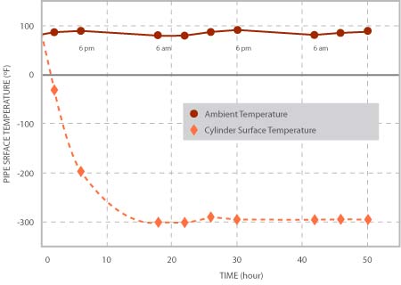
Figure 2, Variations of ambient and Pipe’s outer Surface Temperature with time.
The variations of ice thickness with time at three axial locations of the pipe are shown in Figure 3. As it is to be expected, the rate of ice formation is higher at night (when the ambient temperature was 8 ~ 10 degrees lower than in the day time) than that during the day. From morning to early afternoon, as the ambient temperature increased, some ice melted, resulting in a decrease of the ice thickness. In the first night, the maximum thickness was about 1.5”; the average thickness decreased to about 1.25” during daytime while in the following night the average thickness increased to about 1.75” and decreased to 1.35” during the day time, when the test was stopped.
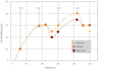
Figure 3, Variations of ice thickness at three locations with time
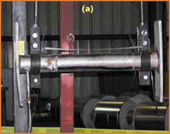
(a) Test facility without ice formation
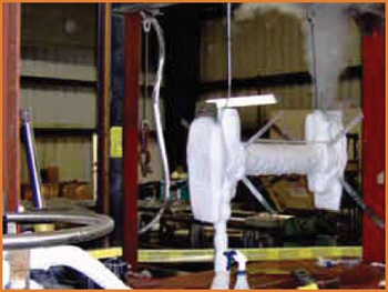
(b) Test facility with ice formation
Polyurethane Components for Pipe Supports
Polyurethanes are different from most plastic materials in that they can be tailored to meet the requirements of varying applications. Soft elastomers in flexible foams with low density are used in cushions and bedding. Tougher elastomers with higher densities are used for soles of shoes and boots. Rigid foams are used in construction, automobiles, furniture, boating, and many other applications.
Polyurethane: History
The commercial potential of polyurethane chemistry was first recognized in the late 1930’s. I.G. Farben (Germany), ICI (U.K.), and du Pont (U.S.A.) developed a variety of applications. ICI introduced rigid foams in 1957. Production line insulation for refrigerators was introduced in 1963. In 1968 General Motors started making polyurethane bumpers for the Pontiac G.T.O. The combination of strength to support loads and thermal insulation made rigid polyurethane foam an attractive material for the cryogenic pipe supports required for major LNG facilities constructed in the 1970’s.
Polyurethane Components: Pipe Supports
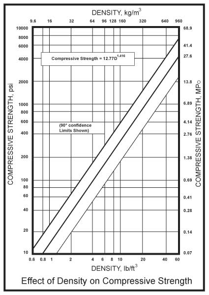
The primary design parameter for the polyurethane component of a pipe support is density because this determines the compressive strength. As shown in Figure 1, on a log-log scale the relation between compressive strength and density is linear. Tensile strength also has a linear log-log relation to density. Because the loads on supports for larger diameter pipes are larger than those on polyurethane components in many other industrial applications, we require higher density materials. For components used in pipe supports with densities from 10 to 40 pounds/cubic foot (160 to 640 kg/cubic meter), particularly those produced in molds, the compressive strength is essentially the same in all directions. Thermal conductivity is another design parameter of concern for the pipe support designer. For rigid foam polyurethane’s, thermal conductivity increases with density. Fortunately, the 10 to 40 pound-density materials are less sensitive to the choice of blowing agent and aging, two concerns for industries which use low density foams to achieve very low thermal conductivity.
Laboratory Testing
Laboratory tests have been developed to characterize the important physical properties of plastics to help guide design and production. The table below shows the ISO and equivalent ASTM tests which are widely applied to rigid polyurethane foams.
|
Standard Tests of Rigid Polyurethane Foams
|
||
|
ISO Number
|
ASTM Number
|
Physical Properties Measured
|
|
844
|
D 1621
|
Compressive stress-strain
|
|
2581
|
C 518
|
Thermal conductivity Flow meter
|
|
2582
|
C 177
|
Thermal conductivity Hot plate
|
|
5490
|
D 2856
|
Closed-cell Content
|
Rigid Foam Production for Pipe Supports
Rigid polyurethane components are produced by mixing two liquids; polyisocyanates and a mixture of polyol, catalysts, water and/or a blowing agent, pigments and other additives. Companies with experience in blending these chemicals can tailor them to the specific application. When the chemicals are combined under controlled conditions, an exothermic reaction begins and the foam begins to expand. With proper control of conditions the reaction continues to completion and a solid product is obtained.
The primary factors which manufacturers must control are temperature, accurate metering of the liquids, mixing, curing time and freedom from contaminants. Many machines have been developed for manufacturers to use for both control and efficient production. At Piping Technology we use RIM (Reaction Injection Molding) machines which provide excellent mixing, temperature control and metering of the chemicals. Our large inventory of molds give us the ability to provide proper geometry with a minimum of waste, reproducible results and maximum productivity of the workforce. Assembly line techniques can be applied when quantities justify this approach. The cure time before de-molding depends on the size of the components.
Chemistry
Rigid polyurethane foams have a relativity large amount of cross-linking as the foams expands. Suppliers of the chemicals control the degree of cross-linking by functionality (higher functionality produces more cross-links) and molecular weight of the components in the blend. Figure 2 shows a photomicrograph image of a cut piece of rigid foam. The closed cells formed during cross-linking can be seen. These rigid cells provide the strength and the interior space provides low thermal conductivity. Water can be used as the blowing agent for foam in this 10 to 40 pound-density range. This avoids the need to use chlorofluorocarbons which were so important in the production of 1 to 2 pound-density insulation prior to modern environmental regulation.
Permeability
The water vapor permeability of rigid polyurethane foam is low but pipe support applications often have a very large temperature differential between the cryogenic fluid inside the pipe and the climate outside the insulating system. For this reason, pipe supports designers use impermeable facings (galvanized, rolled shields), with low-permeable coatings and linings to separate the moisture-laden air outside from the polyurethane component which is in contact with the cold pipe. An effective moisture barrier on the warm side is particularly important for this type of application.
PT&P: Polyurethane Production Capabilities
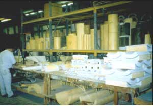
Piping Technology and Products has a complete manufacturing facility for production of polyurethane components required for pipe supports. We invite our customers to visit our facility and observe the fabrication of insulated pipe supports of all types. Our engineers will be happy to discuss the use of rigid foam polyurethane for cryogenic supports.
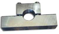
Stresses in Clamp and Saddle
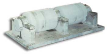
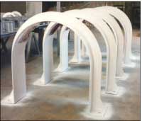 Vibrations produced by rotating machinery are very common for industrial piping systems. Bracing devices can be used to cope with vibration. Hold downs are one of the most widely used pipe support devices to restrain or dampen pipe vibration. A common location for applying a hold down exists near a compressor. The objective is to limit vibration caused by rotating equipment in order to avoid damage to the surrounding piping system. The hold down restrains the vibration introduced by the compressor as it compresses the gases in the pipe line. Hold downs are effective for the control of vibration and/or movement.
Vibration Control: PT&P’s Capabilities
Pipe Technology & Products, Inc. can custom design and fabricate hold downs for any pipe size application. In additional to hold downs, PT&P also offers other types of vibration control devices to accommodate different pipe orientations and locations:
Types:
 Anchor Type (PTP HD-1)
Generally used on pipe lines where little or no insulation is required
Temperature: 750°F
Anchor Type (PTP HD-1)
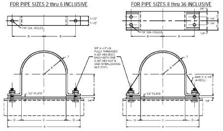
APPLICATION: The PTP Fig. HD-1 is our anchor type hold down. This hold down is generally used in pipe lines where little or no insulation is required.
Material:
Carbon Steel Temperature: 750° Fahrenheit Finish: Black
Galvanized finish Temperature: 200° Fahrenheit
|
Pipe Size
|
A
|
B
|
C
|
D
|
E
|
R
|
T
|
|
2
|
9 3/8
|
3 3/16
|
2 3/8
|
3 1/2
|
15/16
|
1 3/16
|
1/4
|
|
3
|
10 1/2
|
3 3/4
|
3 1/2
|
3 1/2
|
1 1/2
|
1 3/4
|
3/8
|
|
4
|
11 1/2
|
4 1/4
|
4 1/2
|
3 1/2
|
2
|
2 1/4
|
3/8
|
|
6
|
13 5/8
|
5 5/16
|
6 5/8
|
3 1/2
|
3 1/16
|
3 5/16
|
3/8
|
|
8
|
16
|
6 1/2
|
8 5/8
|
3 11/16
|
4 1/16
|
4 5/16
|
3/8
|
|
10
|
19
|
8
|
10 3/4
|
4 1/8
|
5 1/8
|
5 3/8
|
3/8
|
|
12
|
21
|
9
|
12 3/4
|
4 1/8
|
6 1/8
|
6 3/8
|
1/2
|
|
14
|
23
|
10
|
14
|
4 1/2
|
6 3/4
|
7
|
1/2
|
|
16
|
25
|
11
|
16
|
4 1/2
|
7 3/4
|
8
|
1/2
|
|
18
|
27
|
12
|
18
|
4 1/2
|
8 3/4
|
9
|
1/2
|
|
20
|
29
|
13
|
20
|
4 1/2
|
9 3/4
|
10
|
1/2
|
|
24
|
33
|
15
|
24
|
4 1/2
|
11 3/4
|
12
|
1/2
|
|
30
|
39
|
18
|
30
|
4 1/2
|
14 3/4
|
15
|
1/2
|
|
36
|
45
|
21
|
36
|
4 1/2
|
17 3/4
|
18
|
1/2
|
Anchor Type (PTP HD-2)
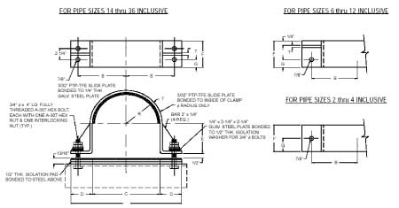
*generally used on compressor lines or similar applications with high temperature and massive thermal movement
*the clamp radius and the base are line with PTFE slide plate, allowing axial movement while restraining lateral movement.
*Temperature: 400°F
|
Pipe Size
|
A
|
B
|
C
|
D
|
E
|
F
|
G
|
R
|
T
|
|
2
|
9 3/8
|
3 9/16
|
2 1/2
|
3 9/16
|
3/4
|
2 1/2
|
1 1/4
|
1 5/16
|
1/4
|
|
3
|
10 3/4
|
4 1/8
|
3 5/8
|
3 9/16
|
1 5/16
|
2 1/2
|
1 1/4
|
1 7/8
|
1/4
|
|
4
|
11 3/4
|
4 5/8
|
4 5/8
|
3 9/16
|
1 13/16
|
2 1/2
|
1 1/4
|
2 3/8
|
1/4
|
|
5
|
13 7/16
|
5 7/16
|
5 11/16
|
3 7/8
|
2 7/8
|
2 1/2
|
1 1/4
|
2 15/16
|
3/8
|
|
6
|
14 1/2
|
6
|
6 3/4
|
3 7/8
|
2 7/8
|
3 1/2
|
1 1/4
|
3 7/16
|
3/8
|
|
8
|
16 1/2
|
7 9/16
|
8 3/4
|
3 7/8
|
3 7/8
|
3 1/2
|
1 1/4
|
4 7/16
|
3/8
|
|
10
|
18 5/8
|
8 1/16
|
10 7/8
|
3 7/8
|
4 15/16
|
3 1/2
|
1 1/4
|
5 1/2
|
3/8
|
|
12
|
21 3/4
|
9 5/8
|
12 7/8
|
4 7/16
|
5 15/16
|
3 1/2
|
1 1/4
|
6 1/2
|
1/2
|
|
14
|
23
|
10 1/4
|
14 1/8
|
4 7/16
|
6 9/16
|
6
|
1 3/8
|
7 1/8
|
1/2
|
|
16
|
25
|
11 1/4
|
16 1/8
|
4 7/16
|
7 9/16
|
6
|
1 3/8
|
8 1/8
|
1/2
|
|
18
|
27
|
12 1/4
|
18 1/8
|
4 7/16
|
8 9/16
|
6
|
1 3/8
|
9 1/8
|
1/2
|
|
20
|
29
|
13 1/4
|
20 1/8
|
4 7/16
|
9 9/16
|
6
|
1 3/8
|
10 1/8
|
1/2
|
|
24
|
33
|
15 1/4
|
24 1/8
|
4 7/16
|
11 9/16
|
6
|
1 3/8
|
12 1/8
|
1/2
|
|
30
|
39
|
18 1/4
|
30 1/8
|
4 7/16
|
14 9/16
|
6
|
1 3/8
|
15 1/8
|
1/2
|
|
36
|
45
|
21 1/4
|
36 1/8
|
4 7/16
|
17 9/16
|
6
|
1 3/8
|
18 1/8
|
1/2
|
Anchor Type (PTP HD-3)
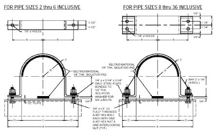
*generally used on compressor lines or similar applications with low thermal movement
*the clamp radius is lined with a belting material designed to absorb shock from vibration
*Temperature: 200°F
*belting material remains impervious to heat up to 200°F
|
Pipe Size
|
A
|
B
|
C
|
D
|
E
|
R
|
T
|
|
2
|
9 7/8
|
3 7/16
|
2 7/8
|
3 1/2
|
1 3/16
|
1 7/16
|
1/4
|
|
3
|
11
|
4
|
4
|
3 1/2
|
1 3/4
|
2
|
3/8
|
|
4
|
12
|
4 1/2
|
5
|
3 1/2
|
2 1/4
|
2 1/2
|
3/8
|
|
6
|
14 1/8
|
5 9/16
|
7 1/8
|
3 1/2
|
3 5/16
|
3 9/16
|
3/8
|
|
8
|
16 1/2
|
6 3/4
|
9 1/8
|
3 11/16
|
4 5/16
|
4 9/16
|
3/8
|
|
10
|
19 1/2
|
8 1/4
|
11 1/4
|
4 1/8
|
5 3/8
|
5 5/8
|
3/8
|
|
12
|
21 1/2
|
9 1/4
|
13 1/4
|
4 1/8
|
6 3/8
|
6 5/8
|
1/2
|
|
14
|
23 1/2
|
10 1/4
|
14 1/2
|
4 1/2
|
7
|
7 1/4
|
1/2
|
|
16
|
25 1/2
|
11 1/4
|
16 1/2
|
4 1/2
|
8
|
8 1/4
|
1/2
|
|
18
|
27 1/2
|
12 1/4
|
18 1/2
|
4 1/2
|
9
|
9 1/4
|
1/2
|
|
20
|
29 1/2
|
13 1/4
|
20 1/2
|
4 1/2
|
10
|
10 1/4
|
1/2
|
|
24
|
33 1/2
|
15 1/4
|
24 1/2
|
4 1/2
|
12
|
12 1/4
|
1/2
|
|
30
|
39 1/2
|
18 1/4
|
30 1/2
|
4 1/2
|
15
|
15 1/4
|
1/2
|
|
36
|
45 1/2
|
21 1/4
|
36 1/2
|
4 1/2
|
18
|
18 1/4
|
1/2
|
Corrosion Protection
This technical bulletin will consider four methods of protecting carbon steel pipe supports components from corrosion; painting, zinc coatings, hot dip galvanizing, and combinations of these. Painting has an advantage when appearance and choice of color are important. Modern painting systems may be appropriate protection in certain environments. Paint provides “barrier” protection to a metal surface. The ability of zinc to provide cathodic protection for carbon steel in addition to barrier protection is a fundamental advantage. In most cases the reduction in life-cycle costs justifies the small additional cost of galvanizing. Indeed painting and galvanizing together can provide a synergistic benefit which may be justified in some cases.
The use of zinc and galvanizing has a long history. The early patents for hot dip galvanizing were issued in France and England in 1836 and 1837. This technology was quickly adopted and was widely used in the late-1800s. In the United States we have bridges more than 100 years old which have galvanized structures. In addition, we have transmission towers and substation structures that are over 70 years old. A pipe rack at a petrochemical plant near Houston was studied after 28 years of service. Measurements of the zinc thickness remaining provided a forecast of another 60 years of service. Pulp and paper mills use galvanized materials in most of their critical environments. It is important to understand the fundamentals which make this “old” technology so cost effective in such a wide variety of applications.
Electrochemistry of Zinc & Carbon Steel
Corrosion is an electrochemical process which occurs when four elements are present; an anode which gives up electrons, a cathode which receives electrons, an electrolyte (which is usually an aqueous solution of acids, bases, or salts) and a metallic current path. The rate at which corrosion occurs depends on the electric potential between the anodic and cathodic areas, the pH of the electrolyte, the temperature, and the water and oxygen available for chemical reactions.
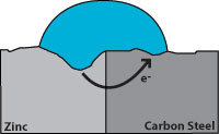 Effect of corrosion on zinc and carbon steel
Hot dip galvanizing has two advantages over a zinc coating. During galvanizing, the molten zinc reacts with the carbon steel to form layers of zinc/iron alloys. Figure 3 shows a galvanized surface with 5 layers, the top layer is 100% zinc and the bottom layer is carbon steel. The alloy layers between have increased hardness to provide mechanical (barrier) protection and because of their zinc content they are also anodic relative to carbon steel. The hardness of these alloy layers provides much more protection from scratches than paint can provide. This is important for most pipe supports applications.
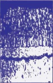
- Eta layer 100%: Zn 70 DPN hardness
- Zeta layer 94% Zn 6% Fe 179 DPN hardness
- Delta layer 90% Zn 10% Fe 224 DPN hardness
- Gamma layer 75% Zn 25% Fe
- Carbon Steel 159 DPN hardness
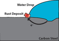
Any coating which provides a barrier to the moisture and oxygen in the air will help protect carbon steel from corrosion. A properly painted surface will provide a barrier, but it is subject to scratching from contact with hard objects. Figure 4 illustrates how rust can grow and damage a painted surface when corrosion begins because the paint barrier is broken by a scratch.
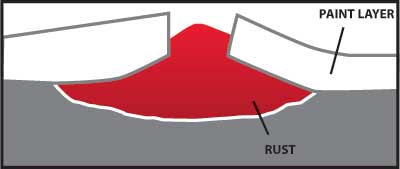
Figure 4
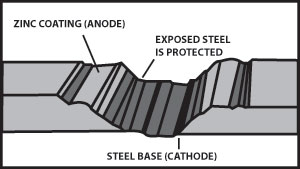
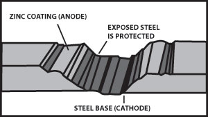
Figure 5 illustrates the cathodic protection provided when a galvanized surface is scratched.
Duplex Systems usually require painting over galvanizing. Some of our customers have specified a duplex system. This is more expensive but it can be justified for certain corrosive environments or for appearance. The American Galvanizing Association suggests the following “rule of thumb” to estimate the service life of a duplex system.
(Duplex System Service Life) = 1.5* (Service Life: HDG Only) + (Service Life: Paint Only)
*The synergistic multiplier of 1.5 is based on the barrier protection the paint provides for the galvanized surface.
At Piping Technology and Products Inc., many customers have returned painted variable and constant spring supports which could no longer function due to corrosion. Costs must be considered during the specification of coatings for pipe supports. The owner and operator of a facility should consider life-cycle costs. Pipe supports are usually a relatively small percentage of the total cost of installing and operating a power plant, petrochemical plant, paper mill or other major facility. The small additional cost of hot dip galvanizing the carbon steel components of pipe supports is most always a wise investment.
For more information you may want to contact the following organization:
American Galvanizing Association-AGA
12200 E. Illif #204 Aurora, CO 80014
ph 800-468-7732
National Association of Corrosion Engineers-NACE
1440 S. Creek Dr. Houston, Tx 77084
ph 713-492-0535
Suitability of Snubbers for Various Applications
By Dr. Hyder Husain Ph.D.
March 9, 2011
Snubbers are used as restraining devices to control abnormal movement of pipes and equipment due to dynamic events such as earthquakes, turbine trips, safety/relief valve discharge, rapid valve closure, or rupture of pipes. The design of a snubber allows free thermal movement of a component during normal operating conditions, but restrains the component in abnormal conditions.
The snubber restraint forces, as described above, can be generated using either mechanical or hydraulic methods.
Hydraulic Snubbers
Hydraulic snubbers have a piston which is relatively unconstrained during relatively low velocities as would be seen in normal thermal expansion/contraction cycles or slow oscillation of pipes. At high displacement rates, the piston “locks up” and the snubber acts as a rigid restraint.
Hydraulic Snubber with an Overall Stroke of 6″
Our commercial hydraulic snubbers have a nominal fluid viscosity of 100 cStokes (cst) @ 40°C. Typically, the motion of the snubber-fluid shuts off the valve when the piston velocity reaches 8”/min or more. As a result, the snubber acts as a rigid component and transfers the shock load to the rigid foundation, saving the upstream components.
Mechanical Snubbers
 Similarly to hydraulic snubbers, mechanical snubbers use a telescoping cylinder to permit free movement of the pipe under normal operating conditions. When the threshold acceleration of 0.02 g’s is exceeded, an internal mechanism of the snubber activates, thereby locking the telescoping cylinder and subsequently producing our restraint force.
Hydraulic vs. Mechanical Snubbers
Because hydraulic snubbers have fewer internal components, they are preferred in outdoor applications or where a corrosive environment is present. Additionally, hydraulic snubbers can be easily designed to accommodate a wide range of pipe displacement.
Mechanical snubbers are optimum solutions for piping used in high radiation areas such as those seen in nuclear power plants because they do not utilize hydraulic fluid that may become degraded in radioactive environments.
Furthermore, mechanical snubbers require less maintenance overall and are considered “solid state” support components in the piping system. Hydraulic snubbers conversely require a routine inspection to detect leaking seals or loss of hydraulic fluid.
Dynamic Response
In regards to dynamic response, mechanical snubbers react consistently regardless of their  position during either compression or extension modes. However, hydraulic snubbers may show some variation in their dynamic response depending upon the piston location. Therefore, when choosing a hydraulic snubber for a piping system, one must carefully determine the amount of stroke needed to adequately position the snubber piston orientation for optimum functionality.
Vibration in a Piping System
By Dr. Hyder Husain Ph.D.
January 6, 2011
Cause of Vibration All piping systems typically used in industrial application are made of elastic material. Elastic materials vibrate even under small perturbations due to their elastic properties. Since solid materials have a non-zero stiffness factor for both volumetric and shear deformations, these perturbations can generate waves with different velocities depending upon the deformation mode. Volumetric perturbations produce transverse waves while shear perturbations produce longitudinal waves.
External Perturbation In an ideal situation, pipe vibration would be non-existent if the fluid could flow through the piping system without any disturbances that would cause perturbation. However, in real-life situations, there are many sources that generate perturbation in the piping system and subsequently cause vibration.
Causes of Perturbation Here we can separate the main causes into a few main categories:
(a) Mechanical, (b) Fluid Induced, (c) Transients
(a) Mechanical:
(i) Perturbation originating from the pump or compressor.
(ii) Mechanical perturbation propagating from other moving mechanical components.
(b) Fluid Induced:
(i) Flow turbulence (broad band spectra): Function of Reynolds number
(ii) Multiphase flow: Propagation of slugs (quasi-periodic) and their implosion/explosion may cause serious vibration.
(iii) Bends & elbows: These produce secondary flows causing further interaction and enhancing strong vertical flows of quasi-periodic nature.
(iv) Valves: Valves cause flow separation and/or direction change which leads to high intensity turbulence (Reynolds number dependent).
(c) Transients:
(i) Sudden rupture of pipe
(ii) Sudden closure of valve
(iii) External forces on the pipe or piping components
Causes of Perturbation Thorough plant design should ensure that the Eigen-modes and Eigen-values of the overall system subjected to external perturbations should not match those of the piping system when subjected to those same external perturbations. Low frequency, long waves will cause immediate problems; whereas high frequency, low amplitude vibrations will cause fatigue failures over time. Therefore, one must be careful in designing the piping system and should use various vibration mitigating devices placed at proper locations. In addition, proper process controls should be used to reduce vibration especially in multiphase flows.
Snubbers: A General Overview
By Dr. Hyder Husain Ph.D.
December 2, 2010
Introduction: PT&P produces various kinds of snubbers. Why snubbers are used and how they function are briefly discussed here.
What are they?: Snubbers are restraining devices used to control the movement of pipe and equipment during abnormal dynamic conditions such as earthquakes, traveling shock waves caused by turbine trips, safety/relief valve discharge, rapid valve closure or accidental rupture of piping.
Where are they used?: Snubbers are extensively used in various applications including chemical plants, power plants (both conventional & nuclear), refineries, and structures such as suspension bridges and tall rise buildings in earthquake-prone areas.
How do they function?: The design of a snubber allows free thermal movement of components during normal operating conditions. Abnormal conditions activate the snubber to become momentarily rigid (locked condition). While locked, the snubber transmits the transient force to the ground or to a permanent structure without causing any damage to the downstream components. As soon as the transient force ceases, the snubber resumes its normal operation.
Types of Snubbers: There are two types of snubbers: (i) hydraulic and (ii) mechanical snubbers with various types of designs. However, the function of any design is the same—to protect the downstream structure from abnormal shocks. Snubbers are designed for various load ratings depending upon the magnitude of seismic activities and the criticality of fluid induced shocks.
Hydraulic Snubbers: This type consists of either two concentric cylinders or two parallel cylinders and their respective moving pistons. Both the main cylinder and the compensating cylinders are filled with fluid. The main and the compensating cylinders are connected to velocity limiting valves and a main piston which works in either a push or pull mode. Under normal operating conditions, the valves remain open and allow the piston to move freely under thermal expansion/contraction of the supported component. When the threshold velocity (typically 8 in. per minute) is reached, the valve activates by closing the flow through the valve (also known as valve locking) and the flow through the system stops momentarily. At this point, the main piston that takes the shock load stops moving and the load is transmitted to the ground or to a permanent structure, thus avoiding any damage to the structure downstream of the snubber. As soon as the shock wave passes, the snubber resumes normal operation.
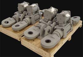 |
|
Hydraulic Snubbers
|
Mechanical Snubber: Similar to hydraulic snubbers, this type of snubber is comprised of a moving cylinder/rod arrangement. Unlike hydraulic snubbers, however, mechanical snubbers use mechanical means to provide the restraint force.
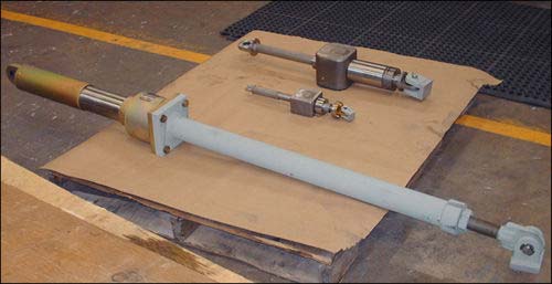 |
|
Mechanical Snubbers
|
MSA Mechanical Snubber: With this type of snubber, the linear movement of the rod connected to the piping component is converted to rotary motion. When the centrifugal acceleration exceeds a certain threshold acceleration (typically 0.02g), a centrifugal type clutch flares out and locks at the peripheral slot of the cylinder and restricts linear motion.
Anchor-Darling Mechanical Snubber: With this type of snubber, the linear motion of the central rod that is connected to the structural component is converted to oscillatory motion via a verge mechanism. This oscillatory motion is in turn converted to rotary motion via a set of gears. As the linear velocity increases, the inertia force generated in the oscillating verge and the train of rotating gears increases. The extent of this increase depends upon the amount of inertial mass and gear train’s angular velocities thereby limiting the velocity of the piping components within the safe limit.
Methods of Protecting Against Corrosion
This technical bulletin will consider four methods of protecting carbon steel pipe supports components from corrosion; painting, zinc coatings, hot dip galvanizing, and combinations of these. Painting has an advantage when appearance and choice of color are important. Modern painting systems may be appropriate protection in certain environments. Paint provides “barrier” protection to a metal surface. The ability of zinc to provide cathdoic protection for carbon steel in addition to barrier protection is a fundamental advantage. In most cases the reduction in life-cycle costs justifies the small additional cost of galvanizing. Indeed painting and galvanizing together can provide a synergistic benefit which may be justified in some cases.
The use of zinc and galvanizing has a long history. The early patents for hot dip galvanizing were issued in France and England in 1836 and 1837. This technology was quickly adopted and was widely used in the late-1800s. In the United States we have bridges more than 100 years old which have galvanized structures. In addition, we have transmission towers and substation structures that are over 70 years old. A pipe rack at a petrochemical plant near Houston was studied after 28 years of service. Measurements of the zinc thickness remaining provided a forecast of another 60 years of service. Pulp and paper mills use galvanized materials in most of their critical environments. It is important to understand the fundamentals which make this “old” technology so cost effective in such a wide variety of applications.
Electrochemistry of Zinc & Carbon Steel
Corrosion is an electrochemical process which occurs when four elements are present; an anode which gives up electrons, a cathode which receives electrons, an electrolyte (which is usually an aqueous solution of acids, bases, or salts) and a metallic current path. The rate at which corrosion occurs depends on the electric potential between the anodic and cathodic areas, the pH of the electrolyte, the temperature, and the water and oxygen available for chemical reactions.
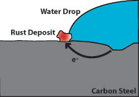
Figure 1 (above) indicates how corrosion damages carbon steel. Note that the pitted area to the right is anodic and gives up electrons while the cathodic area to the left (where water and oxygen from the air are present) is where rust appears. The pitted area where the carbon steel is weakened is not where the rust appears.
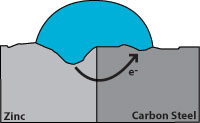
Zinc has a greater tendency to give up electrons than carbon steel, so when both are present, zinc becomes the anode and protects the carbon steel. Figure 2 indicates corrosion with the zinc giving up the electrons and becoming pitted while the carbon steel remains undamaged. From this we see that a zinc coating will protect carbon steel by “sacrificing” itself until the zinc is depleted. The rate of zinc depletion is relatively slow when the pH of the electrolyte is between 4 and 13.
Hot dip galvanizing has two advantages over a zinc coating. During galvanizing, the molten zinc reacts with the carbon steel to form layers of zinc/iron alloys. Figure 3 shows a galvanized surface with 5 layers, the top layer is 100% zinc and the bottom layer is carbon steel. The alloy layers between have increased hardness to provide mechanical (barrier) protection and because of their zinc content they are also anodic relative to carbon steel. The hardness of these alloy layers provides much more protection from scratches than paint can provide. This is important for most pipe supports applications.
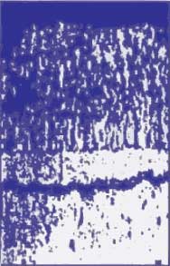
- Eta layer 100: Zn 70 DPN hardness
- Zeta layer 94% Zn 6% Fe 179 DPN hardness
- Delta layer 90% Zn 10% Fe 224 DPN hardness
- Gamma layer 75 Zn 25% Fe
- Carbon Steel 159 DPN hardness
Any coating which provides a barrier to the moisture and oxygen in the air will help protect carbon steel from corrosion. A properly painted surface will provide a barrier, but it is subject to scratching from contact with hard objects. Figure 4 illustrates how rust can grow and damage a painted surface when corrosion begins because the paint barrier is broken by a scratch.
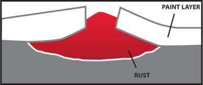
Figure 5 illustrates the cathodic protection provided when a galvanized surface is scratched.
Duplex Systems usually require painting over galvanizing. Some of our customers have specified a duplex system. This is more expensive but it can be justified for certain corrosive environments or for appearance. The American Galvanizing Association suggests the following “rule of thumb” to estimate the service life of a duplex system.
(Duplex System Service Life) = 1.5* (Service Life: HDG Only) + (Service Life: Paint Only)
*The synergistic multiplier of 1.5 is based on the barrier protection the paint provides for the galvanized surface.
At Piping Technology and Products Inc., many customers have returned painted variable and constant spring supports which could no longer function due to corrosion. Costs must be considered during the specification of coatings for pipe supports. The owner and operator of a facility should consider life-cycle costs. Pipe supports are usually a relatively small percentage of the total cost of installing and operating a power plant, petrochemical plant, paper mill or other major facility. The small additional cost of hot dip galvanizing the carbon steel components of pipe supports is most always a wise investment.
For more information you may want to contact the following organization:
American Galvanizing Association-AGA
12200 E. Illif #204 Aurora, CO 80014
Phone – 800-468-7732
National Association of Corrosion Engineers-NACE
1440 S. Creek Dr. Houston, Tx 77084
Phone – 713-492-0535
Comparative Corrosion Resistance Guide
| Medium | Concentration | Temp. °F | 304 Stainless | 316 Stainless | 410 Stainless | 416 Stainless | 430 Stainless | Nickel Alloy 400 | Nickel Alloy C-276 | PVC | High Density Polyethylene | Polypropylene | FRP (Extren® 500/525) |
| Acetic Acid | 20% | 70° | Good | Good | Good | Poor | Good | Fair | Good | Good | Good | Good | Good |
| Acetic Acid | 50% | 70° | Good | Good | Poor | Poor | Fair | Good | Good | Poor | Good | Good | |
| Acetic Acid | 80% | 70° | Good | Good | Poor | Good | Fair | Good | Fair | Fair | Good | ||
| Acetic Acid | 100% | 70° | Good | Good | Good | Poor | Good | Fair | Good | Fair | Good | Fair | |
| Acetic Acid | 50% | Boiling | Fair | Good | Poor | Poor | Fair | Good | Fair | Good | Good | Not Recommended | |
| Acetic Acid | 80% | Boiling | Poor | Good | Poor | Poor | Fair | Good | Poor | Good | Fair | Not Recommended | |
| Acetic Acid | 100% | Boiling | Fair | Good | Poor | Poor | Fair | Good | Poor | Fair | Fair | Not Recommended | |
| Acetic Anhydride | 90% | 70° | Good | Good | Poor | Good | Fair | Good | Poor | Good | Good | Not Recommended | |
| Acetic Anhydride | 90% | Boiling | Good | Good | Fair | Poor | Fair | Fair | Good | Poor | Good | Good | Not Recommended |
| Acetic Vapors | 30% | Hot | Fair | Good | Poor | Fair | Fair | Poor | Poor | Not Recommended | |||
| Acetic Vapors | 100% | Hot | Fair | Poor | Fair | Fair | Poor | Poor | Not Recommended | ||||
| Acetone | 70° | Good | Good | Good | Good | Good | Good | Not Recommended | Not Recommended | Good | Not Recommended | ||
| Acetone | Boiling | Good | Good | Good | Good | Good | Good | Poor | Fair | Fair | Not Recommended | ||
| Acetylene | 70° | Good | Good | Good | Good | Fair | Good | Good | |||||
| Alcohol | 3 ½- 4 ½ % | 160° | Good | Good | Not Recommended | ||||||||
| Alcohol, Ethyl | 70° | Good | Good | Good | Good | Fair | Good | Good | Fair | Good | Not Recommended | ||
| Alcohol, Ethyl | Boiling | Good | Good | Good | Good | Fair | Good | Good | Good | Good | Not Recommended | ||
| Alcohol, Methyl | 70° | Good | Good | Good | Good | Fair | Good | Good | Good | Good | Not Recommended | ||
| Alcohol, Methyl | 150° | Fair | Good | Fair | Fair | Fair | Good | Good | Good | Good | Not Recommended | ||
| Aluminum | Molten | Poor | Poor | Poor | Poor | Poor | Poor | Poor | Poor | Poor | Poor | ||
| Aluminum Acetate | Saturated | 70° | Good | Good | Fair | Good | Good | ||||||
| Aluminum Acetate | Saturated | Boiling | Good | Good | Fair | Fair | Good | ||||||
| Aluminum Chloride | 25% | 70° | Poor | Fair | Poor | Poor | Fair | Good | Good | Good | Good | Good | |
| Aluminum Chloride | Saturated | 70° | Poor | Poor | Fair | Good | Good | Good | Good | Good | |||
| Aluminum Fluoride | 70° | Fair | Poor | Fair | Good | Good | Good | ||||||
| Aluminum Hydroxide | Saturated | 70° | Good | Good | Good | Poor | Fair | Good | Good | Good | |||
| Aluminum Potassium Sulphate | 2% and 10% | 70° | Good | Good | Good | Poor | Fair | Good | Poor | Good | Good | ||
| Aluminum Potassium Sulphate | 2% and 10% | Boiling | Good | Good | Fair | Poor | Fair | Good | Good | Good | Good | ||
| Aluminum Potassium Sulphate | Saturated | Boiling | Good | Good | Fair | Poor | Fair | Good | Good | Fair | Good | ||
| Aluminum Sulphate | 10% | 70° | Good | Good | Poor | Poor | Fair | Good | Good | Good | Good | ||
| Aluminum Sulphate | Saturated | 70° | Good | Good | Poor | Poor | Fair | Good | Good | Fair | Good | ||
| Aluminum Sulphate | 10% | Boiling | Good | Good | Poor | Poor | Poor | Good | Good | Fair | Good | ||
| Aluminum Sulphate | Saturated | Boiling | Good | Good | Poor | Poor | Poor | Good | Good | Fair | Good | ||
| Ammonia (Dry & Moist) | All Concentrations | 70°/212° | Good | Good | Poor | Good | Poor | Good | Good | Good | Good | Not Recommended | |
| Medium | Concentration | Temp. °F | 304 Stainless | 316 Stainless | 410 Stainless | 416 Stainless | 430 Stainless | Nickel Alloy 400 | Nickel Alloy C-276 | PVC | High Density Polyethylene | Polypropylene | FRP (Extren® 500/525) |
| Ammonia (Dry & Moist) | Anhydrous | 70° | Good | Good | Poor | Good | Poor | Good | Fair | Good | Not Recommended | ||
| Ammonia (Dry & Moist) | Anhydrous | Hot | Poor | Poor | Poor | Poor | Poor | Good | Not Recommended | Good | Not Recommended | ||
| Ammonium Bicarbonate | 70° | Good | Good | Poor | Good | Poor | Fair | Poor | Good | Poor | Good | ||
| Ammonium Bicarbonate | Hot | Good | Good | Poor | Good | Poor | Poor | Poor | Good | Poor | Not Recommended | ||
| Ammonium Carbonate | 1%and 5% | 70° | Good | Good | Good | Good | Good | Poor | Fair | Good | Good | Good | Not Recommended |
| Ammonium Carbonate | Aerated | 70° | Good | Good | Good | Good | Good | Poor | Fair | Good | Good | Good | Not Recommended |
| Ammonium Chloride | 1% | 70° | Good | Good | Poor | Good | Good | Good | Good | Good | Good | ||
| Ammonium Chloride | 1%/28%/50% | Boiling | Good | Good | Poor | Fair | Good | Good | Good | Good | |||
| Ammonium Hydroxide | 70° | Good | Good | Good | Good | Good | Not Recommended | Fair | Good | Good | Good | Not Recommended | |
| Ammonium Nitrates | All Concentrations | 70° | Good | Good | Poor | Good | Poor | Fair | Good | Good | Good | Good | |
| Ammonium Nitrates | Saturated | Boiling | Good | Good | Good | Poor | Good | Poor | Poor | Good | Good | Good | |
| Ammonium Oxolate | 5% | 70° | Good | Good | Good | Poor | Good | Fair | Fair | Poor | Good | Poor | |
| Ammonium Perchlorate | 5% | 70° | Good | Good | Good | Good | Good | Fair | |||||
| Ammonium Persulphate | 5% | 70° | Good | Good | Good | Poor | Good | Not Recommended | Fair | Good | Good | Good | Not Recommended |
| Ammonium Phosphate | 5% | 70° | Good | Good | Fair | Good | Fair | Good | Good | Good | Good | Not Recommended
; |
|
| Ammonium Phosphate | Saturated | 70° | Good | Good | Fair | Good | Fair | Good | Good | Good | Good | Not Recommended | |
| Ammonium Sulphate | 1% and 5% | 70° | Good | Good | Fair | Good | Fair | Fair | Good | Good | Good | Good | |
| Ammonium Sulphate | 10% | Boiling | Good | Good | Fair | Fair | Fair | Fair | Good | Good | Good | Good | |
| Ammonium Sulphate | Saturated | Boiling | Good | Good | Fair | Fair | Fair | Fair | Good | Poor | Good | Good | |
| Ammonium Sulphite | 70° | Good | Good | Not Recommended | Good | Good | Good | ||||||
| Ammonium Sulphite | Boiling | Good | Good | Not Recommended | Good | ||||||||
| Amyl Acetate | Concentrated | 70° | Good | Good | Good | Good | Good | Good | Not Recommended | Not Recommended | Not Recommended | ||
| Amyl Chloride | 70° | Good | Good | Fair | Fair | Fair | Good | Not Recommended | Not Recommended | Not Recommended | |||
| Aniline | 3% | 70° | Good | Good | Good | Good | Fair | Fair | Not Recommended | Not Recommended | Good | ||
| Aniline | Conc. Crude | 70° | Good | Good | Good | Good | Fair | Fair | Poor | Good | Fair | ||
| Aniline Hydrochloride | 70° | Poor | Poor | Poor | Poor | Not Recommended | Not Recommended | Not Recommended | Not Recommended | ||||
| Antimony | Molten | Poor | Poor | Poor | Poor | Good | Good | ||||||
| Antimony Trichlordie | 70° | Poor | Poor | Poor | Poor | Fair | Fair | Good | Good | Good | |||
| Arsenic Acid | 150° | Good | Good | Not Recommended | Fair | Good | Good | Good | |||||
| Barium Carbonate | 70° | Good | Good | Good | Good | Fair | Fair | Good | Good | Good | Good | ||
| Barium Chloride | 5% | 70° | Good | Good | Fair | Fair | Good | Good | Good | Good | Good | ||
| Barium Chloride | Saturated | 70° | Good | Good | Good | Good | Fair | Good | Good | Good | Good | Good | |
| Barium Chloride | Aqueous Sol. | Hot | Good | Good | Fair | Good | Good | Good | Good | Not Recommended | |||
| Barium Nitrate | Aqueous Sol. | Hot | Good | Good | Poor | Fair | Fair | ||||||
| Medium | Concentration | Temp. °F | 304 Stainless | 316 Stainless | 410 Stainless | 416 Stainless | 430 Stainless | Nickel Alloy 400 | Nickel Alloy C-276 | PVC | High Density Polyethylene | Polypropylene | FRP (Extren® 500/525) |
| Barium Sulphate | 70° | Good | Good | Good | Good | Fair | Good | Good | Good | Fair | |||
| Barium Sulphide | Saturated | 70° | Good | Good | Good | Good | Good | Poor | Good | Good | Good | Good | Not Recommended |
| Barley-Malt & Hops | 70° | Good | Good | Good | Good | Good | Good | ||||||
| Beer | 70° | Good | Good | Poor | Good | Good | Good | Good | Good | Good | |||
| Benzene | 70° | Good | Good | Good | Good | Good | Good | Fair | Not Recommended | Not Recommended | Poor | Not Recommended | |
| Benzoic Acid | 70° | Good | Good | Good | Fair | Good | Good | Good | Fair | Good | |||
| Benzol | 70° | Good | Good | Good | Good | Fair | Poor | Poor | Good | ||||
| Blood (Meat Juices) | Cold | Good | Good | Good | Good | Good | |||||||
| Borax | 5% | Hot | Good | Good | Good | Good | Good | Good | Good | Good | Good | Good | |
| Boric Acid | 5% | Hot | Good | Good | Good | Good | Fair | Good | Good | Good | Good | ||
| Boric Acid | Saturated | Boiling | Good | Good | Good | Good | Good | Fair | Good | Good | Good | Good | |
| Bromine | 70° | Poor | Poor | Poor | Poor | Poor | Good | Not Recommended | Not Recommended | ||||
| Buttermilk | 70° | Good | Good | Good | Good | Good | Good | ||||||
| Butyric Acid | 5% | 70° | Good | Good | Good | Good | Fair | Good | Not Recommended | Fair | Good | Good | |
| Butyric Acid | 5% | 150° | Good | Good | Good | Poor | Fair | Not Recommended | Good | Not Recommended | |||
| Butyric Acid. Aqueous Sol | SP.G .964 | Boiling | Good | Good | Good | Poor | Poor | Poor | Poor | Good | |||
| Calcium Carbonate | 70° | Good | Good | Good | Fair | Fair | Good | Good | Good | Good | |||
| Calcium Chlorate | Dilute Sol. | 70° | Good | Good | Fair | Fair | Good | Good | Good | Good | |||
| Calcium Chlorate | Dilute Sol. | Hot | Good | Good | Fair | Fair | Good | Good | Good | Good | |||
| Calcium Chloride | Dilute Sol. | 70° | Good | Good | Fair | Fair | Good | Good | Good | Good | Good | ||
| Calcium Chloride | Cone. Sol. | 70° | Good | Good | Fair | Fair | Good | Good | Good | Good | Good | ||
| Calcium Hydroxide | 10% | Boiling | Good | Good | Fair | Good | Good | Good | Good | Not Recommended | |||
| Calcium Hydroxide | 20% | Boiling | Good | Good | Fair | Good | Good | Good | Good | Not Recommended | |||
| Calcium Hydroxide | 50% | Boiling | Fair | Good | Fair | Good | Good | Good | Good | Not Recommended | |||
| Calcium Hypochlorite | 2% | 70° | Good | Good | Poor | Poor | Fair | Not Recommended | Good | Good | Good | Good | Good |
| Calcium Sulphate | Saturated | 70° | Good | Good | Good | Poor | Fair | Good | Good | Good | Good | ||
| Carbolic Acid | CP | 70° | Good | Good | Poor | Good | Fair | Good | Good | Good | Good | ||
| Carbolic Acid | CP | Hot | Good | Good | Good | Fair | Good | Good | Poor | Good | |||
| Carbolic Bisulphide | 70° | Good | Good | Good | Poor | Fair | Fair | Good | |||||
| Carbon Dioxide (Dry) | 70° | Good | Good | Good | Good | Good | Good | Good | Good | ||||
| Carbon Monoxide Gas | 1400° | Good | Good | Good | Good | Poor | Poor | Good | Good | Good | Good | ||
| Carbon Monoxide Gas | 1600° | Good | Good | Good | Poor | Poor | Good | Good | Good | Good | |||
| Carbon Tetrachloride | CP (dry) | 70° | Good | Good | Good | Good | Good | Good | Good | Not Recommended | Not Recommended | Fair | Not Recommended |
| Carbon Tetrachloride | CP (dry) | Boiling | Good | Good | Good | Good | Good | Fair | Fair | Poor | Poor | Poor | Not Recommended |
| Medium | Concentration | Temp. °F | 304 Stainless | 316 Stainless | 410 Stainless | 416 Stainless | 430 Stainless | Nickel Alloy 400 | Nickel Alloy C-276 | PVC | High Density Polyethylene | Polypropylene | FRP (Extren® 500/525) |
| Carbon Tetrachloride | Aqueous Sol. 10% | 70° | Fair | Good | Poor | Poor | Fair | Good | Good | Poor | Poor | Poor | Not Recommended |
| Carbonic Acid | 70° | Fair | Fair | Fair | Fair | Poor | Good | Good | Good | Good | Good | ||
| Chinosol | Antis. Sol. 1-500 | 70° | Good | Good | |||||||||
| Chlorascetic Acid | 70° | Poor | Fair | Poor | Poor | Poor | Poor | Good | Fair | Fair | Good | Not Recommended | |
| Chlorbenzol | Pure, Dry | 70° | Good | Good | Good | Fair | Fair | ||||||
| Chloric Acid | 70° | Poor | Poor | Poor | Not Recommended | Fair | Good | Not Recommended | |||||
| Chlorinated Water | Saturated | 70° | Poor | Fair | Poor | Fair | Good | Good | Good | Fair | Not Recommended | ||
| Chorine Gas | Dry Gas | 70° | Fair | Fair | Fair | Good | Good | Good | Fair | Not Recommended | |||
| Chorine Gas | Moist Gas | 70° | Poor | Poor | Poor | Poor | Good | Fair | Fair | Not Recommended | |||
| Chloroform | Dry Gas | 70° | Good | Good | Good | Good | Fair | Not Recommended | Not Recommended | Not Recommended | Not Recommended | ||
| Chromic Acid | CP 10% | 70° | Good | Good | Fair | Fair | Good | Not Recommended | Good | Not Recommended | Good | Good | Not Recommended |
| Chromic Acid | CP 10% | Boiling | Fair | Good | Poor | Poor | Not Recommended | Fair | Good | Good | Good | Not Recommended | |
| Chromic Acid | CP 50% | Boiling | Fair | Fair | Poor | Poor | Not Recommended | Poor | Fair | Good | Fair | Not Recommended | |
| Chromic Acid (Cont. S0₃) | 50% Commercial | 70° | Good | Good | Poor | Poor | Poor | Not Recommended | Fair | Fair | Good | Fair | Not Recommended |
| Chromic Acid (Cont. S0₃) | 50% Commercial | Boiling | Poor | Poor | Poor | Poor | Poor | Not Recommended | Poor | Fair | Good | Poor | Not Recommended |
| Chromium Plating Bath | 70° | Good | Good | Not Recommended | Good | ||||||||
| Cider | 70° | Good | Good | Good | Good | Good | Good | Good | |||||
| Citric Acid | 10% | 70° | Good | Good | Poor | Poor | Good | Fair | Good | Good | Good | Good | Good |
| Citric Acid | 25% | 70° | Good | Good | Poor | Good | Fair | Good | Good | Good | Fair | Good | |
| Citric Acid | 50% | 70° | Good | Good | Poor | Poor | Fair | Good | Good | Good | Fair | Good | |
| Citric Acid | 10% | Boiling | Good | Good | Poor | Poor | Poor | Poor | Good | Good | Good | Poor | Good |
| Citric Acid | 25% | Boiling | Poor | Good | Poor | Poor | Poor | Good | Good | Good | Poor | Good | |
| Citric Acid | 50% | Boiling | Poor | Good | Poor | Poor | Poor | Good | Good | Good | Poor | Good | |
| Coca-Cola Syrup (Pure) | 70° | Good | Good | Good | Good | Good | Good | ||||||
| Coffee | Boiling | Good | Good | Good | Good | Good | Good | Good | |||||
| Copper Acetate | Saturated | 70° | Good | Good | Good | Poor | Fair | ||||||
| Copper Carbonate | Sat. Sol. In 50% NH₄oh | 70° | Good | Good | Good | Not Recommended | Fair | Good | Good | ||||
| Copper Chloride | 1% Aerated | 70° | Good | Good | Good | Not Recommended | Good | Good | Good | Good | Good | ||
| Copper Chloride | 5% Aerated | 70° | Fair | Poor | Not Recommended | Good | Good | Good | Good | Good | |||
| Copper Cyanide | Saturated | Boiling | Good | Good | Good | Not Recommended | Good | Good | Good | Good | Not Recommended | ||
| Copper Nitrate | 5% | 70° | Good | Good | Good | Good | Not Recommended | Fair | Good | Good | Good | Good | |
| Copper Nitrate | 50% | Boiling | Good | Good | Not Recommended | Not Recommended | Good | Good | Good | Good | |||
| Copper Sulphate | 5% Aerated | 70° | Good | Good | Good | Good | Poor | Good | Good | Good | Good | Good | |
| Copper Sulphate | Saturated | Boiling | Good | Good | Good | Good | Not Recommended | Good | Good | Good | Good | Good | |
| Medium | Concentration | Temp. °F | 304 Stainless | 316 Stainless | 410 Stainless | 416 Stainless | 430 Stainless | Nickel Alloy 400 | Nickel Alloy C-276 | PVC | High Density Polyethylene | Polypropylene | FRP (Extren® 500/525) |
| Cottonseed Oil | 70° | Good | Good | Good | Good | Good | Good | Good | Good | Good | Good | Good | |
| Creosote (Coal Tar) | Hot | Good | Good | Good | Good | Fair | Fair | Poor | |||||
| Cyanogen Gas | 70° | Good | Good | Fair | |||||||||
| Dichloroethane | Boiling | Good | Good | Fair | Fair | Poor | Poor | Not Recommended | |||||
| Dinitrochlorobenzene | Melted and Solidified | 70° | Good | Good | Good | Good | Good | Not Recommended | |||||
| Dyewood Liquor | 70° | Good | Good | Good | Good | ||||||||
| Epsom Salt (Magnesium Sulphate) | Cold & Hot | Good | Good | Fair | Good | Good | Good | Good | Good | Good | |||
| Ether | 70° | Good | Good | Good | Fair | Fair | Not Recommended | Not Recommended | |||||
| Ethyl Alcohol | 10% to 100% | 70° | Good | Good | Good | Good | Fair | Good | Good | Fair | Good | ||
| Ethyl Chloride (Dry) | 70° | Good | Good | Good | Good | Fair | Fair | Not Recommended | Not Recommended | Not Recommended | |||
| Ethylene Glycol | Conc. | 70° | Good | Good | Not Recommended | Good | Fair | Good | Good | Good | Good | Good | |
| Fatty Acids | 100% | 70° | Fair | Good | Fair | Fair | Fair | Good | Good | Good | Good | Good | |
| Ferric Chloride | All Concentrations | 70° | Not Recommended | Good | Good | Good | Good | Good | |||||
| Ferric Hydroxide | 70° | Good | Good | Fair | Fair | ||||||||
| Ferric Nitrate | All Concentrations | 70° | Good | Good | Good | Good | Good | Not Recommended | Good | Good | Good | Good | Good |
| Ferric Sulphate | 10% to 50% | 70° | Fair | Fair | Fair | Fair | Fair | Good | Good | Good | Good | ||
| Ferrous Chloride | Saturated | 70° | Fair | Not Recommended | Fair | Good | Good | Good | Good | ||||
| Ferrous Sulphate | 10% | 70° | Good | Good | Poor | Poor | Fair | Fair | Fair | Good | Good | Good | Good |
| Ferrous Sulphate | 10% | Boiling | Good | Good | Poor | Poor | Not Recommended | Fair | Good | Good | Fair | Good | |
| Fluorine (Gas) | 70° | Poor | Poor | Poor | Poor | Poor | Good | Good | Not Recommended | Good | Not Recommended | ||
| Formalin | Formaldehyde 40% | 70° | Good | Good | Poor | Poor | Good | Fair | Fair | ||||
| Formic Acid | 5% | 70° | Good | Good | Poor | Poor | Good | Fair | Good | Poor | Good | Good | Good |
| Formic Acid | 10% | 70° | Good | Good | Poor | Good | Fair | Good | Good | Good | Good | Good | |
| Formic Acid | 50% | 70° | Good | Good | Poor | Fair | Good | Good | Good | Good | Not Recommended | ||
| Formic Acid | 100% | 70° | Good | Good | Poor | Poor | Fair | Good | Good | Good | Good | Not Recommended | |
| Formic Acid | 10% | Boiling | Good | Good | Poor | Poor | Fair | Good | Fair | Good | Fair | Not Recommended | |
| Formic Acid | 50% | Boiling | Good | Good | Poor | Poor | Fair | Good | Fair | Good | Fair | Not Recommended | |
| Formic Acid | 100% | Boiling | Good | Good | Poor | Fair | Good | Good | Fair | Not Recommended | |||
| Fruit Juices | 70° | Good | Good | Good | Good | Good | Good | Good | Good | Good | Good | ||
| Fuel Oil | Hot | Good | Good | Good | Good | Good | Fair | Good | |||||
| Furfural | 70° | Good | Good | Fair | Fair | Not Recommended | Not Recommended | Not Recommended | |||||
| Gallic Acids | 5% | 70° | Good | Good | Good | Good | Fair | Fair | Good | Not Recommended | Good | ||
| Gallic Acids | 5% | 150° | Good | Good | Poor | Good | Fair | Fair | Good | Good | |||
| Gallic Acids | Saturated (212°F) | Boiling | Good | Good | Good | Fair | Fair | Good | Good | ||||
| Medium | Concentration | Temp. °F | 304 Stainless | 316 Stainless | 410 Stainless | 416 Stainless | 430 Stainless | Nickel Alloy 400 | Nickel Alloy C-276 | PVC | High Density Polyethylene | Polypropylene | FRP (Extren® 500/525) |
| Gasoline | 70° | Good | Good | Good | Fair | Good | Good | Good | Fair | Good | Poor | Good | |
| Gasoline | 70° | Good | Good | Poor | Good | Good | Good | Good | Good | Good | Good | ||
| Glue | Dry | 70° | Good | Good | Good | Good | Good | Good | Good | Good | Good | ||
| Glue | Solution Acid | 70° and 140° | Fair | Good | Good | Good | |||||||
| Glycerine | 70° | Good | Good | Good | Good | Good | Good | Good | Good | Good | Good | Good | |
| Hydrobromic Acid | Poor | Poor | Poor | Poor | Poor | Fair | Fair | Good | Good | Good | |||
| Hydrochloric Acid | All Concentrations | 70° | Poor | Poor | Poor | Poor | Poor | Poor | Good | Fair | Good | Good | Good |
| Hydrocyanic Acid | Good | Good | Fair | Fair | Fair | Fair | Fair | Good | Good | Good | |||
| Hydrofluoric Acid | All Concentrations | Hot and 70° | Poor | Poor | Poor | Poor | Good | Fair | Fair | Good | Good | Not Recommended | |
| Hydrofluosilicic Acid | 70° | Poor | Poor | Poor | Poor | Fair | Fair | Not Recommended | Good | Not Recommended | |||
| Hydrogen Peroxide | 70° | Good | Good | Good | Good | Good | Fair | Good | Good | Good | Good | Not Recommended | |
| Hydrogen Peroxide | Boiling | Good | Good | Good | Good | Fair | Good | Good | Fair | Good | Not Recommended | ||
| Hydrogen Sulphide | Dry | 70° | Good | Good | Poor | Poor | Good | Not Recommended | Good | Good | Good | Good | Good |
| Hydrogen Sulphide | Wet | 70° | Fair | Good | Poor | Poor | Fair | Not Recommended | Good | Good | Good | Good | Good |
| Iodine | 70° | Poor | Poor | Poor | Poor | Poor | Good | Good | Not Recommended | Fair | Good | ||
| Iodoform | 70° | Good | Good | Poor | Fair | ||||||||
| Kerosene | 70° | Good | Good | Good | Good | Good | Good | Not Recommended | Good | Good | |||
| Ketchup | 70° | Good | Good | Good | Good | Good | |||||||
| Lactic Acid | 1,5, and 10% | 70° | Good | Good | Good | Not Recommended | Fair | Fair | Good | Good | Good | ||
| Lactic Acid | 1% | Boiling | Good | Good | Good | Not Recommended | Fair | Poor | Poor | Poor | Not Recommended | ||
| Lactic Acid | 5% | Boiling | Fair | Good | Fair | Not Recommended | Fair | Poor | Poor | Poor | Not Recommended | ||
| Lactic Acid | 10% | Boiling | Fair | Good | Poor | Not Recommended | Fair | Poor | Poor | Poor | Not Recommended | ||
| Lard | 70° | Good | Good | Good | Good | Good | Good | Not Recommended | Fair | ||||
| Lead | Molten | 1000° | Fair | Fair | Poor | Poor | Fair | Not Recommended | Not Recommended | Not Recommended | Not Recommended | ||
| Lead Acetate | 5% | Boiling | Good | Good | Fair | Fair | Good | Good | |||||
| Linseed Oil | 70° | Good | Good | Fair | Good | Good | Good | Good | Not Recommended | Good | Good | ||
| Lysol | 70° | Good | Good | Poor | Poor | Poor | Good | Good | |||||
| Magnesium Carbonate | All Concentrations | 70° | Good | Good | Good | Fair | Fair | Good | Good | Good | Good | ||
| Magnesium Chloride | 1% and 5% | 70° | Good | Good | Poor | Poor | Good | Good | Good | Good | Good | Good | Good |
| Magnesium Chloride | 1% and 5% | Hot | Fair | Good | Poor | Poor | Fair | Good | Good | Good | Good | Good | Not Recommended |
| Magnesium Hydroxide | 70° | Good | Good | Good | Good | Good | Good | Good | Good | Good | Not Recommended | ||
| Magnesium Nitrate | All Concentrations | 70° | Good | Good | Good | Good | Good | Good | Good | Good | Not Recommended | ||
| Magnesium Sulphate | 10% | 70° | Good | Good | Good | Fair | Fair | Good | Fair | Good | Good | ||
| Magnesium Sulphate | 10% | Boiling | Good | Good | Fair | Fair | Good | Good |
Considering All Movement in Pipe Support Design
December 21, 2010
Each component of a piping system has a job to do. Making sure a system can function correctly and efficiently requires that designers thoroughly account for each component’s design from the conditions at installation (cold) to those during system operation (hot). One requirement of pipe supports, critical to every piping run, is that they accommodate pipe displacement, or movement, generated during operation without adding excessive stress to the overall system. Movement results from changes in temperature, load, or any other operating characteristics that affect the forces at play — whether inside the pipeline or in the environment surrounding the system.
Anticipating both the magnitude and direction of every possible movement during a process can be complex, but doing so is vital. If the pipe support design does not accommodate all movements properly, the finished system will likely deteriorate or fail.
Designers must always remember that movement can occur in three dimensions: axially, laterally (perpendicular to but in the same plane as the pipe), and vertically (usually parallel to the pipe support, in the plane connecting the pipe to the structural element). Failure to consider these movements could result in time-consuming and costly retrofitting or repair in addition to any labor and materials that might have been wasted, damaged, or lost. Also, designers must consider that any particular support might move more than would be reflected if only the starting and ending positions of components in a process cycle are examined. In other words, the extent of intermediate movements can and often does exceed the net movement.
Pipe support assemblies can be classified according to both their level of engagement (active or passive) and function (load-bearing, guiding, or anchoring).
We designate support configurations whose primary capabilities are always engaged as active, whereas passive support configurations simply follow the movement of the pipe during normal operation. However, disturbances such as severe weather, impact, abnormal vibration or seismic events, will activate these otherwise passive supports, which then function as active anchoring devices.
Pipe support functions include load bearing, guiding, or anchoring. A load bearing support will uphold the weight of the pipe while allowing possible movement in all three dimensions. A guide will uphold the weight of the pipe while restricting movement in up to two dimensions. An anchor will completely restrict pipe movement in all three dimensions while bearing the weight, side, and thrust loads.
Active support components
-
Shoes: Used as anchors, bearings, and guides. Material used in fabrication usually matches piping material (e.g., carbon steel, stainless steel, chrome molybdenum or “chrome-moly”) and may also depend on operating temperatures.
-
Hangers: Used to support the pipe weight. Rigid hangers consist of components that do not permit vertical movement (in the axis connecting the pipe to the structural steel base) but do permit lateral or axial swinging. Spring hangers allow both vertical motion and either lateral or axial swinging. Hangers usually consist of a carbon steel structural attachment (e.g., lug plate, beam clamp), a carbon steel rod or rod assembly, and a pipe attachment (e.g., clamp, clevis, roller) fabricated of a material matching that of the pipe.
-
Struts: Used in either tension or compression to withstand a pipe force. The movement allowed is determined by the strut’s orientation (hanging, horizontal, or vertical). Consist of an end bracket connected to a clamp element (e.g., yoke, clevis) fabricated of carbon steel.
- Sway braces: Primarily used to restrain forces other than that of the supported pipe weight. Part of the pipe movement can be accommodated by changing the orientation of the brace, as with a sway strut, with the sway brace spring coil allowing additional movement via compression and decompression. Usually consist of a carbon steel structural attachment, a carbon steel spring coil, and a pipe attachment fabricated of a material matching that of the pipe.
-
Customized supports: A category that includes project- or industry-specific components. Examples include custom-built frames upon which pipe will rest and multi-pipe channel assemblies. Sometimes called random hangers.
Passive support components
-
Snubbers: Used to restrain piping undergoing unwanted abrupt movement in one axis. Under normal operating conditions, snubbers simply “follow” the movement of the pipe, but when subjected to shock loading, the snubber, which can be mechanical or hydraulic, is activated and thereafter acts as a rigid restraint. The amount of stroke provided as part of the snubber design determines how much pipe movement is allowed under normal conditions.
Designers must consider that the above support configurations all allow some movement depending upon the overall size, orientation, and configuration of the assembly. For example, hanger assemblies can accommodate translational motion producing swing angles of +/- 4 degrees maximum. This means that designers may be able to accommodate greater pipe movement by incorporating longer support assemblies into the design, rather than introducing additional support components.
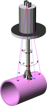
When active and passive support assemblies, comprised of standard components, cannot meet specific system requirements, designers can add auxiliary components, which are designed to extend the range of motion that these supports can accommodate during normal operation.
Auxiliary components
-
Travelers: Used to translate the forces exerted on hangers, a type of active support, across horizontal planes in conjunction with the movement of the pipe. Single horizontal travelers translate forces across one horizontal plane; dual horizontal travelers translate forces across two planes. Consist of rectangular box with a lug protruding from the center and are usually fastened between the structural steel and the rest of the pipe support assembly. Usually fabricated from carbon steel.
-
Rollers: Used to translate forces at the support location on the pipe to a new position in the piping system. Consist of a rolling mechanism attached to the active support component; the other end can either be in direct contact with the pipe or connected via a saddle attached to the pipe. Commonly fabricated of carbon steel; fabrication with polyurethane reduces the overall weight of the component.
-
Slide plates (slide bearing plates): Used to reduce friction associated with axial and lateral movements. The reduction in the friction forces helps reduce stresses on active support components during the pipe movement. Fabricated from carbon steel bonded to polytetrafluoroethylene (PTFE), 25% glass filled, for systems operating in environments cooler than 400 ºF. Can also use graphite, Bronzphite®, or marinite bonded to steel.
The following is an example illustrating the necessity of thoroughly reviewing all movements associated with pipe deflection during a given thermal cycle. In the initial (cold) position, a hydraulic snubber, attached both to stationary structural steel via an end bracket and to a pipe element via a three-bolt clamp, was installed at a cylinder position of 1 inch extension, with a total stroke available of 6 inches. An overall analysis indicated that the final operating (hot) position of the pipe would require that the snubber extend 4.5 inches (which could be accommodated by the remaining stroke of the hydraulic snubber cylinder).
After being put into service, the seals of the snubber were damaged, indicating that the cylinder, at some point, had been completely retracted or extended. Review of the pipe’s position indicated that it was correct according to the original design specifications.
However, a more thorough review of the pipe system revealed that, prior to reaching full operating conditions, the movement of the pipe created a condition in which the overall length of the snubber should have been reduced (retracted) by 1.5 inches. But, because the original set point of the snubber allowed a maximum of only 1 inch of contraction, the continued pipe movement stressed the snubber beyond its capabilites once it reached its fully contracted position (zero extension), thus damaging the support assembly.
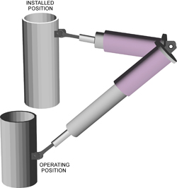
To correct the problem, the original snubber was replaced with one that had an overall available stroke of 12 inches, allowing the initial set point to be increased to a cylinder position of 3 inches of extension. This new snubber design accommodated all pipe deflection throughout the entire process cycle.
Optimal use of pipe supports
• Become familiar with Manufacturers Standardization Society Standard Practices 58 and any other industry- or company-specific codes that apply to your project, such as American Society of Mechanical Engineers B31.1 for power and B31.3 for process engineering (both of which refer to MSS SP-58). The manufacturer and installation team should also be familiar with these standards and how to accommodate any specific requirements that apply to your project.
• Collect and use good data: Know the full range of loads and movement the piping system will handle during a full operating cycle, and remember that movement in the real world occurs in all three dimensions.
• Make note of other factors that can affect piping loads, such as temperature, weight, states of matter, and external conditions.
February 2008 News
PT&P’s Technical Information is Now Easier to Browse
|
|
|
|
|
|
|
|
|
|
|
|
|
|
|
|
|
|
|
|
|
|
|
|
|
|
|
|
|
|
|
|
|
|
|
|

