ASME Defines Inspection Criteria for High Energy Piping

February 23, 2021

B31.1 Operations and Maintenance

According to ASME B31.1 Chapter VII Par. 140 a program shall be established for the assessment and documentation of the condition of all CPS (Covered Piping Systems) in power plants.

CPS Systems are defined in Chapter 1 Par 100.2, as systems on which condition assessments are to be conducted. This includes the following systems as a minimum.

NPS 4 and larger main steam, hot reheat steam, cold reheat steam, and boiler feedwater piping.

NPS 4 and larger systems that operate above 750°E (400°C or above 1,025 psi (7,100 kPa)


Other systems may be included as CPS by an Operating Company, based on their judgment. Appendix V of the code is titled ‘Recommended Practice for Operation, Maintenance, and Modification of Power Piping Systems’. This addendum is non-mandatory; however many  Power Industry operating companies’ insurance carriers are now invoking Appendix V with increasing frequency, and this is affecting the conditions of their agreements with the operating companies.

Piping Technology and Products Inc. (PT&P) has for some time been performing surveys and assessments in accordance with part H of Par. 140, which requires hot and cold walk-down readings and assessment of pipe supports, operated within the creep regime of the pipe.  These assessments are helpful in identifying, sagging lines, deformation of supports, and damage caused by upset conditions, and/or incidents, attributable to operational malfunctions, dynamic/thermal or hydraulic events.

PT&P has been performing this service for many power generation companies. Preparation of documentation, retrieval, and compilation of files for a CPS assessment, has just been completed for a major U.S power generation company. Ten large power plants were involved, and the original predominantly high-energy pipe support drawings, all engineered and designed by PT&P, were retrieved from PT&P archives dating back ten years.

We will be happy to answer any of your technical questions about our survey capabilities, as well as any other engineering or field services that your organization may need.

If you need assistance, we are available 24×7 for emergencies or reach our field service team directly.

 

ASME Code Pig Launchers and Receivers with a Safety Locking System

January 3, 2011
Asme Code Pig Launchers And Receivers With A Safety Locking System
ASME Code Pig Launchers and Receivers

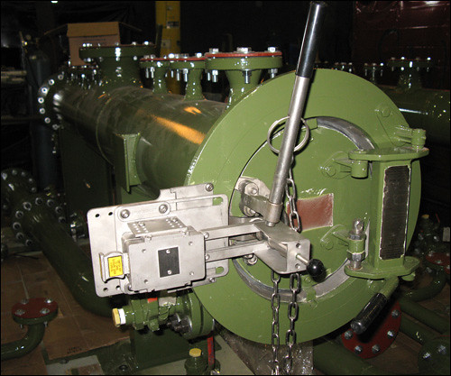
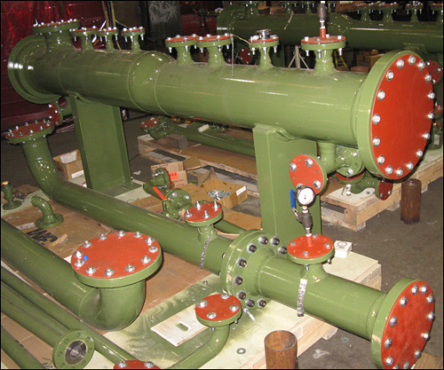
The pig launchers and receivers were designed for a coal-bed methane gas production facility in Colorado. They are equipped with an integral safety locking system which works on the principle of mechanical key interlocking (transfer of keys). This system avoids serious injuries from human error and insures safety of personnel.

Asme Code Pig Launchers And Receivers With A Safety Locking System
Safety Locking System

One starter key per launcher/receiver is kept in a box located in the control room. Each lock is executed with two keys. When the first valve is opened with this starter key, it releases the second key. This key is transferred to next valve which releases second key from that valve and so on and so forth. This process guides the operator through the specified sequence for opening and closing valves with unique a key for each step.

Do you see a need for pig launchers in your piping system? Request pricing today!

Request-A-Quote

48″ I.D. ASME Code Process Vessel

June 10, 2009


48&Quot; I.d. Asme Code Process Vessel
48" I.D. ASME Code Process Vessel
48&Quot; I.d. Asme Code Process Vessel
48" I.D. ASME Code Process Vessel

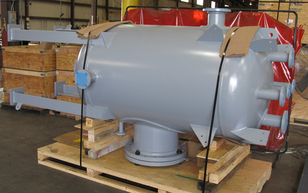
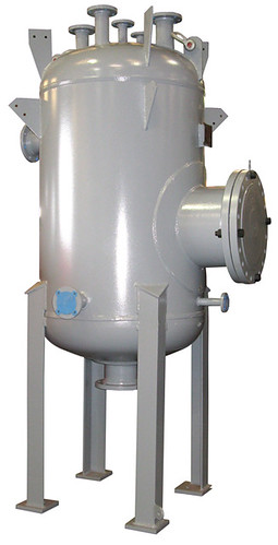
This process vessel has an inside diameter of 48″ and measures 60″ tangent to tangent. The overall height of this vessel is 81″, and measures 120″ including the legs. It is fabricated from 1/2″ 516-70 carbon steel material. This vessel is designed and fabricated according to ASME Section VIII Div 1 codes. It has a capacity of 500 gallons with an internal design pressure of 50 PSIG. The maximum acceptable working pressure is 178 PSIG. This process vessel was heat treated for stress corrosion resistance in the field and 100% x-ray tested and hydro-tested at 231 PSIG prior to being shipped to the customer. This vessel was designed for the customer as a replacement vessel for one in the field that had already provided 20 years of service in a mildly corrosive environment.

Sweco Fab, Inc. worked with the customer to provide a vessel that was even more efficient than the previous one by including 1/8″ thicker walls, an additional 12″ between tangents, heat treatment, an internal drip plate, and an OSHA compliant ladder and platform.

Want to learn more about pressure vessels and tanks? Watch a Sweco Fab webinar now!

Access-Our-Webinar-Archives

90" O.D. Duct Work for an Ammonia Plant

April 25, 2008

90&Quot; O.d. Duct Work For An Ammonia Plant
90" O.D. Duct Work for an Ammonia Plant

90&Quot; O.d. Duct Work For An Ammonia Plant
90" O.D. Duct Work for an Ammonia Plant

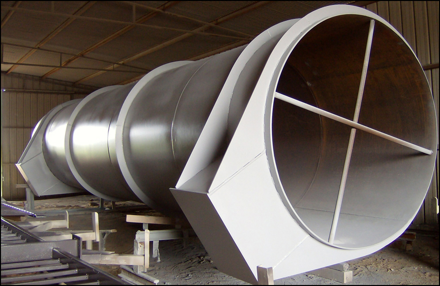
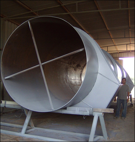
The duct work has an outside diameter of 90 inches and is 38 feet long. The duct assembly is fabricated entirely from ASTM A516-70 carbon steel. The assembly has two support bases and stiffening rings that provide strength and rigidity for the duct work. The assembly is a section of air supply duct in an Ammonia Plant.

Do you require duct work for your piping system? Get pricing today!
Request-A-Quote

84" Diameter Seawall Outfall Flow Regulating Device

August 20, 2004
84&Quot; Diameter Seawall Outfall Flow Regulating Device
Installation of FRP Bundles in the Pipe
84&Quot; Diameter Seawall Outfall Flow Regulating Device
84" Diameter Seawall Outfall Flow Regulating Device

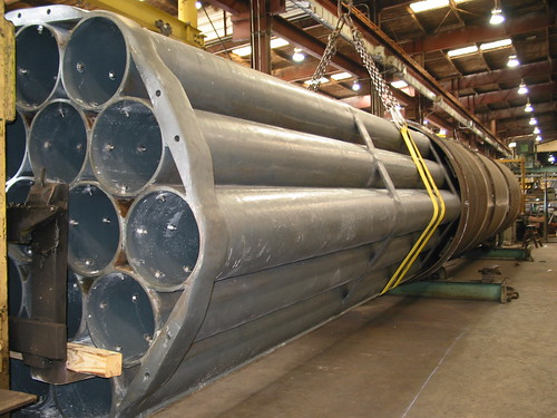
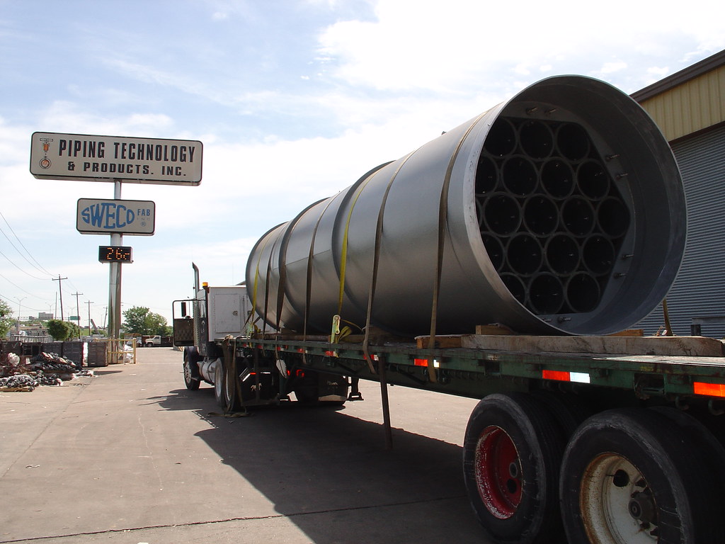
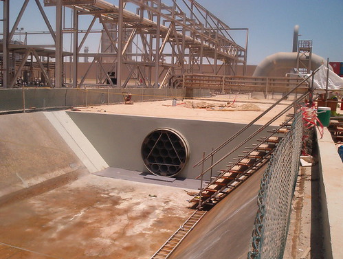
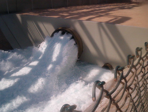
Sweco Fab, Inc. recently designed and manufactured a 30,000 lb. Seawall Outfall Flow Regulating Device for a sea water outlet in Qatar. This 320 long flow conditioner is designed to allow water to flow through evenly. There are nineteen 16 FRP pipes inside an 84 diameter carbon steel pipe. The pipe bundle is secured within the 84 diameter shell pipe using spring washers, which keep the bundle tight and allows for differential expansion between the steel and FRP.

84&Quot; Diameter Seawall Outfall Flow Regulating Device
Installation of Flow Device On-Site


84&Quot; Diameter Seawall Outfall Flow Regulating Device
Flow Device in Use

Want to learn more about the other products fabricated by Sweco Fab? Instantly view a Sweco Fab webinar today!


Access-Our-Webinar-Archives


ASME Catalyst Storage Bins

May 11, 2001
Asme Catalyst Storage Bins
ASME Catalyst Storage Bins

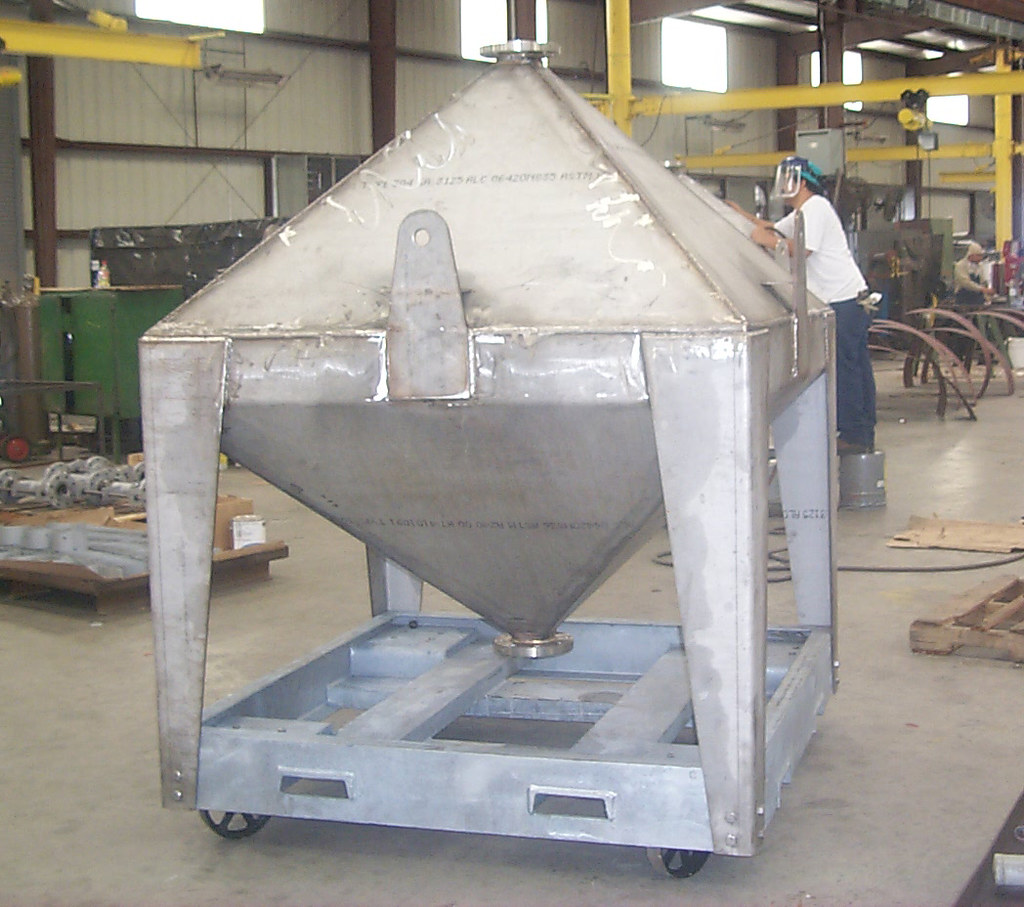
Sweco Fab, Inc., the ASME code fabrication shop of Piping Technology & Products, Inc., designed and built eleven Catalyst storage bins for a large chemical company in Geismer, Louisiana. The catalyst storage bins were fabricated from 304 stainless steel and designed for 6 psig @ 300oF.

Want to learn more about various products of Sweco Fab, Inc. Visit out website webinars today!


Access-Our-Webinar-Archives

Wet Air Fan Cyclone for High Density Polyethylene Project

May 5, 1994
Wet Air Fan Cyclone For High Density Polyethylene Project
Wet Air Fan Cyclone for High Density Polyethylene Project

Sweco Fab, Inc., a wholly subsidiary of Piping Technology & Products, Inc., and an ASME and API code vessel shop recently unveiled their design of a wet air fan cyclone for a new high density polyethylene project.

The barrel, which is a twenty-one feet long, tapers upward from a twelve-inch diameter base to a six foot diameter top. Ears on the exterior of the barrel are provided for support and alignment. Air inlet is designed to mate with other components forming part of the process equipment. The fan cowling has outboard ears to facilitate ease of test, assembly and maintenance. The cyclone was rolled and formed from ¼ inch carbon steel and weighs 4,000 lb.

Want to learn more about Sweco Fab, Inc.? Visit out webinar archives!

Access-Our-Webinar-Archives

Top