Meet the presenters of PT&P’s Online Courses. Click on each video to learn about each course’s objectives, course outline, course module content, and grading breakdown.
Learn more here about PT&P’s online courses and register for a course
Meet the presenters of PT&P’s Online Courses. Click on each video to learn about each course’s objectives, course outline, course module content, and grading breakdown.
Learn more here about PT&P’s online courses and register for a course
The necessary steps for installing all expansion joints shall be pre-planned. The installers shall be made aware of these steps as well as the installation instructions furnished by the manufacturer. The most critical phases of the expansion joint installation are as follows.
Care shall be exercised to prevent any damage to the thin bellows section, such as dents, scores, arc strikes and weld spatter.
No movement of the expansion joint (compression, extension, offset, rotation and especially torsion) due to piping misalignment, for example, shall be imposed which has not been anticipated and designed into the movement capability of the expansion joint. If such movements are imposed, they can result in system malfunction, damage to the bellows or other components in the system. Specifically, cycle life can be substantially reduced, forces imposed on adjacent equipment may exceed their design limits, internal sleeve clearances may be adversely affected, and the pressure capacity and stability of the bellows may be reduced.
Any field pre-positioning shall be performed in accordance with specific instructions which include both the direction and magnitude of the movement.
Anchors, guides and pipe supports shall be installed in strict accordance with the piping system drawings. Any field variances from planned installation may affect proper functioning of the expansion joint and must be brought to the attention of a competent design authority for resolution.
The expansion joint, if provided with internal sleeves, shall be installed with the proper orientation with respect to flow direction.
After the anchors or other fixed points are in place and the piping is properly supported and guided, the expansion joint shipping devices should normally be removed in order to allow the expansion joint to compensate for changes in ambient temperature during the remainder of the construction phase.
The number of expansion joints used on a pipe depends on the length of the pipe, the pressure, the temperature, and the size. Upon knowing these design conditions, we can inform you of the number of expansion joints the pipeline requires.
Using expansion joints on piping depends upon the configuration of the piping where you will place the expansion joint to absorb thermal expansion or contraction.
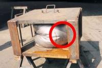
The burst test is primarily conducted on bellows. Normally, hydraulic pressure is slowly increased until failure occurs. Based on the burst test results, a safety factor is applied. This establishes the ultimate pressure rating.

The objective of the burst test is to determine the ultimate pressure resistance. This test is primarily conducted on bellows. Normally, hydraulic pressure is slowly increased until failure occurs. Based on the burst test results, a safety factor is applied. This establishes the ultimate pressure rating.

PT&P Verifies New Designs for LNG Phenolic Base Support with Load Testing

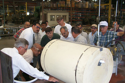
Piping Technology & Products, Inc. performs thorough product testing to verify new designs to a LNG Laminated Phenolic base support for an E&C company located in Houston, Texas. In order to determine the failure loads for a 30″ diameter, pre-insulated shoes and a 6″ diameter Laminated Phenolic base support respectively, PT&P performed lateral-load and axial load tests. The load tests performed ensure the pre-insulated pipe shoes can safely sustain the specified design load. The insulated shoes tested for the E&C company will be in service in 2001 at Atlantic LNG, where they will be used to support the liquid nitrogen gas (LNG) lines.
Big Ton Springs Installation Guide
 1. Measure the existing installed load setting height to make sure that the big ton spring will fit tightly into the space provided. Shim from below as needed to ensure proper fit.
2. Place the big ton spring in the designated location, making sure that all required slide plates, shims, or auxiliary steel are in their proper positions.
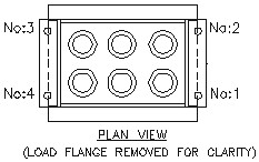
3. Travel stop bolts can be released after all testing has been done. The travel stops are painted red and located on each end of the big ton spring. Follow the steps below to release the travel bolt stops. Please refer to the drawings to the left.
(a) Turn the nut on travel stop bolt No. 1 one-half turn; repeat on bolts 2 through 4.
(b) Repeat in this sequential order until the load is released. The load has now been transferred to whatever the big ton spring is supporting.
4. CAUTION: Be sure that the nuts on the travel stop bolts are backed off enough to accommodate the appropriate travel (Example: 1 inch of travel – the nuts should be backed off by 2 inches from the bottom of the travel stop plate.)
5. At this time the Lifting Eye Bolts may be removed.
Tension Systems
In some cases, a straight line system of axial bellows anchors and guides is not practical or desired; or there is no reasonable way/ place to anchor the bellows thrust loads. In such cases self restrained bellows assemblies may be used, such as the double hinge restrained bellows shown below. Thermal expansion (or contraction) in the long pipe is absorbed by an offset deflection of the double hinge assembly. Bellows thrust load is carried by hinge bars, gimbals, tie rods or other such devices; hence normal tension is maintained in the pipe system and main anchors and full lateral restraint guides are unnecessary.