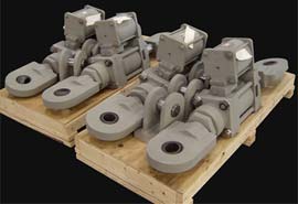
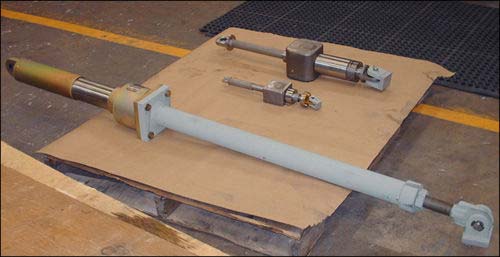
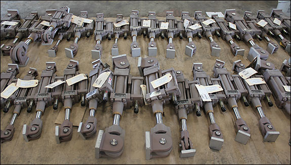
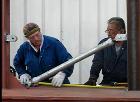
Hydraulic Snubbers Designed for a Steam Generator in Mexico
February 26, 2018
Type:
Hydraulic Snubbers
Size:
24″ up to 30″ Pin-To-Pin | Cylinder Dia. 1.5″ to 3.25″
Material:
Carbon Steel
Design:
3,000 lb. to 20,000 lb., with a 6″ Stroke
Testing:
Standard Quality Control
PT&P designed Fig. 510 AD short strut hydraulic snubbers for a steam generator at a facility in Mexico. The snubbers ranged in length from 24″ up to 30″ pin-to-pin with cylinder diameters of 1.5″ to 3.25″. A total of 48 snubbers were fabricated from carbon steel and designed for an operating load ranging from 3,000 lb. to 20,000 lb., with a 6″ stroke. Snubbers are used for systems where unrestrained thermal movement must be allowed except during cyclic disturbance. Hydraulic snubbers are designed to protect the piping system when a sudden, heavy load is applied (such as an earthquake of high intensity), which can cause serious vibrations leading to damage and possible failure of the piping system.
Pipe Support Field Service: Problem Resolution
November 27, 2017
** Turn up your speakers to hear the audio. Please be patient as the screen will become visible
shortly after the speaker begins the presentation. You may click the monitor icon below each
video to view the webinar in full-screen mode.
NOTE: PDH credits are NOT offered for our recorded webinars.
View the Slides for Above Webinar Here
Pipe Support Field Inspection, Installation & Maintenance
** Turn up your speakers to hear the audio. Please be patient as the screen will become visible
shortly after the speaker begins the presentation. You may click the monitor icon below each
video to view the webinar in full-screen mode.
NOTE: PDH credits are NOT offered for our recorded webinars.
How to Install a Sway Strut
October 9, 2017
Shock Control, Restraint, and Support Devices Webinar
** Turn up your speakers to hear the audio. Please be patient as the screen will become visible
shortly after the speaker begins the presentation. You may click the monitor icon below each
video to view the webinar in full-screen mode.
NOTE: PDH credits are NOT offered for our recorded webinars.
View the Slides for Above Webinar Here
Suitability of Snubbers for Various Applications
By Dr. Hyder Husain Ph.D.
March 9, 2011
Snubbers are used as restraining devices to control abnormal movement of pipes and equipment due to dynamic events such as earthquakes, turbine trips, safety/relief valve discharge, rapid valve closure, or rupture of pipes. The design of a snubber allows free thermal movement of a component during normal operating conditions, but restrains the component in abnormal conditions.
The snubber restraint forces, as described above, can be generated using either mechanical or hydraulic methods.
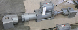
Hydraulic Snubbers
Hydraulic snubbers have a piston which is relatively unconstrained during relatively low velocities as would be seen in normal thermal expansion/contraction cycles or slow oscillation of pipes. At high displacement rates, the piston “locks up” and the snubber acts as a rigid restraint.
Hydraulic Snubber with an Overall Stroke of 6″
Our commercial hydraulic snubbers have a nominal fluid viscosity of 100cStrokes @ 40°C. Typically, the motion of the snubber-fluid shuts off the valve when the piston velocity reaches 8”/min or more. As a result, the snubber acts as a rigid component and transfers the shock load to the rigid foundation, saving the upstream components.
Mechanical Snubbers Similarly to hydraulic snubbers, mechanical snubbers use a telescoping cylinder to permit free movement of the pipe under normal operating conditions. When the threshold acceleration of 0.02 g’s is exceeded, an internal mechanism of the snubber activates, thereby locking the telescoping cylinder and subsequently producing our restraint force.
Hydraulic vs. Mechanical Snubbers
Because hydraulic snubbers have fewer internal components, they are preferred in outdoor applications or where a corrosive environment is present. Additionally, hydraulic snubbers can be easily designed to accommodate a wide range of pipe displacement.
Mechanical snubbers are optimum solutions for piping used in high radiation areas such as those seen in nuclear power plants because they do not utilize hydraulic fluid that may become degraded in radioactive environments.
Furthermore, mechanical snubbers require less maintenance overall and are considered “solid state” support components in the piping system. Hydraulic snubbers conversely require a routine inspection to detect leaking seals or loss of hydraulic fluid.
Dynamic Response
In regards to dynamic response, mechanical snubbers react consistently regardless of their position during either compression or extension modes. However, hydraulic snubbers may show some variation in their dynamic response depending upon the piston location. Therefore, when choosing a hydraulic snubber for a piping system, one must carefully determine the amount of stroke needed to adequately position the snubber piston orientation for optimum functionality.
Vibration in a Piping System
By Dr. Hyder Husain Ph.D. January 6, 2011
Cause of Vibration All piping systems typically used in industrial application are made of elastic material. Elastic materials vibrate even under small perturbations due to their elastic properties. Since solid materials have a non-zero stiffness factor for both volumetric and shear deformations, these perturbations can generate waves with different velocities depending upon the deformation mode. Volumetric perturbations produce transverse waves while shear perturbations produce longitudinal waves.
External Perturbation In an ideal situation, pipe vibration would be non-existent if the fluid could flow through the piping system without any disturbances that would cause perturbation. However, in real-life situations, there are many sources that generate perturbation in the piping system and subsequently cause vibration.
Causes of Perturbation Here we can separate the main causes into a few main categories:
(a) Mechanical, (b) Fluid Induced, (c) Transients
(a) Mechanical:
(i) Perturbation originating from the pump or compressor.
(ii) Mechanical perturbation propagating from other moving mechanical components.
(b) Fluid Induced:
(i) Flow turbulence (broad band spectra): Function of Reynolds number
(ii) Multiphase flow: Propagation of slugs (quasi-periodic) and their implosion/explosion may cause serious vibration.
(iii) Bends & elbows: These produce secondary flows causing further interaction and enhancing strong vertical flows of quasi-periodic nature.
(iv) Valves: Valves cause flow separation and/or direction change which leads to high intensity turbulence (Reynolds number dependent).
(c) Transients:
(i) Sudden rupture of pipe
(ii) Sudden closure of valve
(iii) External forces on the pipe or piping components
Causes of PerturbationThorough plant design should ensure that the Eigen-modes and Eigen-values of the overall system subjected to external perturbations should not match those of the piping system when subjected to those same external perturbations. Low frequency, long waves will cause immediate problems; whereas high frequency, low amplitude vibrations will cause fatigue failures over time. Therefore, one must be careful in designing the piping system and should use various vibration mitigating devices placed at proper locations. In addition, proper process controls should be used to reduce vibration especially in multiphase flows.
Snubbers: A General Overview
By Dr. Hyder Husain Ph.D. December 2, 2010
Introduction: PT&P produces various kinds of snubbers. Why snubbers are used and how they function are briefly discussed here.
What are they?: Snubbers are restraining devices used to control the movement of pipe and equipment during abnormal dynamic conditions such as earthquakes, traveling shock waves caused by turbine trips, safety/relief valve discharge, rapid valve closure or accidental rupture of piping.
Where are they used?: Snubbers are extensively used in various applications including chemical plants, power plants (both conventional & nuclear), refineries, and structures such as suspension bridges and tall rise buildings in earthquake-prone areas.
How do they function?: The design of a snubber allows free thermal movement of components during normal operating conditions. Abnormal conditions activate the snubber to become momentarily rigid (locked condition). While locked, the snubber transmits the transient force to the ground or to a permanent structure without causing any damage to the downstream components. As soon as the transient force ceases, the snubber resumes its normal operation.
Types of Snubbers: There are two types of snubbers: (i) hydraulic and (ii) mechanical snubbers with various types of designs. However, the function of any design is the same—to protect the downstream structure from abnormal shocks. Snubbers are designed for various load ratings depending upon the magnitude of seismic activities and the criticality of fluid induced shocks.
Hydraulic Snubbers: This type consists of either two concentric cylinders or two parallel cylinders and their respective moving pistons. Both the main cylinder and the compensating cylinders are filled with fluid. The main and the compensating cylinders are connected to velocity limiting valves and a main piston which works in either a push or pull mode. Under normal operating conditions, the valves remain open and allow the piston to move freely under thermal expansion/contraction of the supported component. When the threshold velocity (typically 8 in. per minute) is reached, the valve activates by closing the flow through the valve (also known as valve locking) and the flow through the system stops momentarily. At this point, the main piston that takes the shock load stops moving and the load is transmitted to the ground or to a permanent structure, thus avoiding any damage to the structure downstream of the snubber. As soon as the shock wave passes, the snubber resumes normal operation.
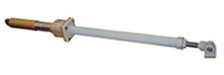
Hydraulic Snubbers
Mechanical Snubber: Similar to hydraulic snubbers, this type of snubber is comprised of a moving cylinder/rod arrangement. Unlike hydraulic snubbers, however, mechanical snubbers use mechanical means to provide the restraint force.
Mechanical Snubbers
MSA Mechanical Snubber: With this type of snubber, the linear movement of the rod connected to the piping component is converted to rotary motion. When the centrifugal acceleration exceeds a certain threshold acceleration (typically 0.02g), a centrifugal type clutch flares out and locks at the peripheral slot of the cylinder and restricts linear motion.
Anchor-Darling Mechanical Snubber: With this type of snubber, the linear motion of the central rod that is connected to the structural component is converted to oscillatory motion via a verge mechanism. This oscillatory motion is in turn converted to rotary motion via a set of gears. As the linear velocity increases, the inertia force generated in the oscillating verge and the train of rotating gears increases. The extent of this increase depends upon the amount of inertial mass and gear train’s angular velocities thereby limiting the velocity of the piping components within the safe limit.
Hydraulic & Mechanical Snubbers
July 31, 2017
INSTALLATION OF HYDRAULIC SNUBBERS:
STEP 1: Check that front paddle is securely fastened to the piston rod. If loose, tighten the connection by means of holding the piston rod on the wrench flats provided and tightening the paddle against it. DO NOT use a pipe wrench on the chromed shaft of the rod. Try to minimize the amount of rotation of the piston rod within the cylinder to prevent possible scoring or seal damage. Torque the connection to between 15 and 25 ft-lb. for all cylinder sizes.
STEP 2: If required, attached the extension piece to the rear of the cylinder or check the torque of the nuts if already assembled. Note: When tightening the extension piece nuts, use a wrench on the tie-rod nuts at the piston rod end of the cylinder to apply a counter-torque. If this procedure is not followed, the cylinder tie rods will loosen. Torque the nuts to the valves listed in the chart below.
CYCL SIZE (KIPS)
BORE SIZE (INCHES)
THREAD (UNC)
TORQUE
(FT-LB.)
3
1.5
3/8 — 16
30
10
2.5
1/2 — 13
60
20
3.3
5/8 — 11
100
30
4.0
5/8 — 11
100
50
5.0
7/8 — 9
230
70
6.0
1 — 8
300
130
8.0
1 1/4 — 7
700
200
10.0
1 3/4 — 5
1500
STEP 3: Consult the hanger detail to determine the required as-built cold pin-to-pin dimension. The extension piece comes equipped with a threaded rod connection to accommodate field length adjustments. Sight holes are provided in the extension pipe to ensure proper thread engagement. The male threads must be visible through these holes for proper load carrying capability. A lock nut is provided to freeze the adjustment. Torque to 50 ft-lb. for all cylinder sizes. For hanger assemblies not equipped with extension pieces (FIG. 510 AD) field length adjustment must be accomplished by repositioning the supporting structures or the cylinder cold set. Approval of new cold set by Shaw FCI should be obtained. Refer to Section E for this procedure.
STEP 4: Orient each end attachment or pipe clamp to ensure that the available alignment provided by the ball bushings is within the allowed 10 degree cone of action.
STEP 5: Hoist the assembly into place. Cylinders equipped with remote reservoirs can have the reservoir de-coupled at this time provided it will not be necessary to reposition the cylinder piston rod during installation. Reconnect the reservoir after the assembly has been pinned in place. NOTE: Due to the pressurized design of Shaw FCI reservoirs, there is no concern for orientation as it will function properly in any spatial orientation. It is recommended that the elevation of the remote reservoir be at or above that of the main cylinder.
The load pins provided with the assembly fit into close tolerance holes for which care must be exercised during installation. Removal and insertion should be accomplished carefully and without undue force. Spacer washers are provided to ensure proper function of the ball bushing alignment feature. The load pins are provided with cotter pins which must be securely installed. Any relocation of the assembly to clear an interference should be brought to the attention of the project engineer. Adherence to project tolerance guidelines should be observed.
STEP 6: Remove and discard the piston rod locking clamp (if supplied). Recheck all bolted connections. For units supplied with remote reservoirs, ensure that proper connections are made and that the flexible hose is free from kinks. Visually examine the entire assembly for erection damage, paying particular attention to the chromed surface of the piston rod. This completes the installation of the assembly.
To Maintain Hydraulic Snubbers
Under normal operating conditions hydraulic snubbers are maintenance free. In severe service (usually involving excessive vibration or high temperatures) the seals may become damaged, causing a loss of fluid. In this case the snubber must be completely disassembled, new seals must be installed, and the snubber must be refilled with fluid.
INSTALLATION OF MECHANICAL SNUBBERS
First, the snubber must be set at the cold position. Under normal operations, the snubber will extend in the positive direction from the initial (cold) position to the operating (hot) position. In rare installations, the snubber may be expected to move in the negative direction by some known amount. The cold position must be set so that the snubber will never closer than ½ to 1 in from the end of its stroke. In most cases, this means that the cold setting will be ½ to 1 in from one end of its stroke range. At the operating conditions the snubber should have at least 1 in of possible travel.The snubber should be installed with its axis parallel to the direction of expected impulsive load. This may or may not be the direction of thermal movement. If the two movements are not in the same direction, there are some additional installation considerations. In this case the snubber should normally be ordered with ball joints at both ends, as shown in the diagram below. The snubber should be mounted so that the major expected thermal movement is in the plane of the ball joints.The overall length is adjustable from 2″ to 6″ by means of the threaded rod on the extension end of the unit.
Mechanical Snubber Diagram
CAUTION: Do not use the piston side threaded rod end for adjustment. Full thread engagement is critical for safe operation.
To Install Mechanical Snubbers
1. Determine the direction and magnitude of thermal motion and impulse load.Adjust the snubber so that after the thermal expansion, the snubber will be in the middle of its travel range. Temporarily install unit in the operating position. Tack weld end brackets to the fixed structure and to the pipe that it is to control. For units furnished with a pipe clamp connection, install the clamp at this time. (CAUTION: Do Not Allow Weld Spatter To Contact Snubber Unit). After tack welding, remove pivot pins from both ends of the snubber assembly, set the unit aside and complete welding. Tighten pipe clamp bolts if applicable. Reinstall snubber assembly between end brackets and replace pivot pins and cotters.
2. Installation is now complete, and the snubber assembly is ready for operation.
We use cookies on our website to give you the most relevant experience by remembering your preferences and repeat visits. By clicking “Accept”, you consent to the use of ALL the cookies.
This website uses cookies to improve your experience while you navigate through the website. Out of these, the cookies that are categorized as necessary are stored on your browser as they are essential for the working of basic functionalities of the website. We also use third-party cookies that help us analyze and understand how you use this website. These cookies will be stored in your browser only with your consent. You also have the option to opt-out of these cookies. But opting out of some of these cookies may affect your browsing experience.
Necessary cookies are absolutely essential for the website to function properly. These cookies ensure basic functionalities and security features of the website, anonymously.
Cookie
Duration
Description
cookielawinfo-checkbox-analytics
11 months
This cookie is set by GDPR Cookie Consent plugin. The cookie is used to store the user consent for the cookies in the category "Analytics".
cookielawinfo-checkbox-functional
11 months
The cookie is set by GDPR cookie consent to record the user consent for the cookies in the category "Functional".
cookielawinfo-checkbox-necessary
11 months
This cookie is set by GDPR Cookie Consent plugin. The cookies is used to store the user consent for the cookies in the category "Necessary".
cookielawinfo-checkbox-others
11 months
This cookie is set by GDPR Cookie Consent plugin. The cookie is used to store the user consent for the cookies in the category "Other.
cookielawinfo-checkbox-performance
11 months
This cookie is set by GDPR Cookie Consent plugin. The cookie is used to store the user consent for the cookies in the category "Performance".
viewed_cookie_policy
11 months
The cookie is set by the GDPR Cookie Consent plugin and is used to store whether or not user has consented to the use of cookies. It does not store any personal data.
Functional cookies help to perform certain functionalities like sharing the content of the website on social media platforms, collect feedbacks, and other third-party features.
Performance cookies are used to understand and analyze the key performance indexes of the website which helps in delivering a better user experience for the visitors.
Analytical cookies are used to understand how visitors interact with the website. These cookies help provide information on metrics the number of visitors, bounce rate, traffic source, etc.
Advertisement cookies are used to provide visitors with relevant ads and marketing campaigns. These cookies track visitors across websites and collect information to provide customized ads.
 Similarly to hydraulic snubbers, mechanical snubbers use a telescoping cylinder to permit free movement of the pipe under normal operating conditions. When the threshold acceleration of 0.02 g’s is exceeded, an internal mechanism of the snubber activates, thereby locking the telescoping cylinder and subsequently producing our restraint force.
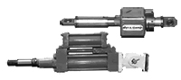 position during either compression or extension modes. However, hydraulic snubbers may show some variation in their dynamic response depending upon the piston location. Therefore, when choosing a hydraulic snubber for a piping system, one must carefully determine the amount of stroke needed to adequately position the snubber piston orientation for optimum functionality.