New Design for High Temperature Supports

March 30, 2022

How a New Design was Developed During an Emergency Shut Down


View / Download Technical Bulletin (PDF)

Piping Technology & Products designed and manufactured new pipe supports for high-temperature pipelines at an existing power plant in August of 2002. This new design was the product of a customer’s urgent need during an emergency shut-down and the unique pipe support requirements. The original large-bore pipe supports on this high-energy pipeline were not optimally designed for the key operating conditions and as a result, failed to support the pipelines during their thermal movements. The previously supplied OEM pipe supports did not prevent (or insulate) heat transfer from the pipelines to the supporting pipe rack steel. These issues led to the plant shut down due to safety and operational considerations by the client and we were called to help.

PT&P was called in after the original supports failed again. Upon our field service technicians’ inspection, we recommended a new design brought on by the unique requirements of installation and time constraints. The power plant was in critical condition and needed a specialized minimum downtime “plan-of-action.” PT&P’s engineering and manufacturing teams worked quickly on the new design.

Fea Drawing Pipe Shoe

Engineering utilized FEA to both design the plate material and thickness required to support the various loads for the new pipe shoe and calculated the required frictional clamping force for line temperatures ranging from 650°F to 1100°F. The new supports were then manufactured on an expedited basis, supports were on-site for the client in less than 2 weeks from when the PO was placed. Our field service team traveled to the plant location and removed the failed OEM supports, and installed the newly designed supports which are still in operation today, and have replaced other OEM supports throughout their facilities nationwide.

Installation New Shoes Restoration Inspection3
Because the elevations of all the piping were fixed, PT&P had to develop a pipe support design that would dissipate heat and protect the PTFE 25% glass-filled slide plates (installed beneath the pipe shoe to reduce friction) from thermal damage by utilizing a design concept called “Natural Draft Air Cooling.” Natural Draft Air Cooling has several advantages over previous designs:

    1. Since the insulation does not carry any mechanical load with the new design, insulation material can be chosen solely based on its thermal properties. In this particular case, cyclic loading had caused insulation failure in the previous design. This problem was now alleviated.
    2. The new support provides effective restraint for multiple components of loads, X, Y, Z, Rotational, and Translational dependent on the location. In particular, Axial and Torsional loads are readily accommodated. These types of loads usually present difficulties for supports that rely on insulation to support a given load.
    3. The newly designed supports are easily installed in the field by attaching them to the pipe with bolted pipe clamps. Thus, there is no field welding.

PT&P REF. ORIGINAL POST 10102017 / Technical Bulletin 2009

Benefits of G10 Micarta® for Insulation

July 2, 2019

Download PDF

Pipe Clamps

G10 Micarta® can be very cost-effective insulation as compared to Polyurethane foam (PUF), especially for medium and large shoes. It offers tremendous benefits at various stages of a project, including but not limited to:

  • Procurement
  • Installation
  • Handling, transportation, and storage
  • Plant Maintenance
53 Cryogenic Pipe Supports With Micarta Insulation For A Lng Plant
Cryogenic Pipe Supports with Micarta® Insulation for an LNG Plant

Major Advantage of G10 Micarta® Supports for Procurement

G10 Micarta® supports involve fewer steps to manufacture, allowing for a quicker fabrication turnaround. It takes 2-3 weeks less on average than PUF supports for delivery. This enables the ability to catch up on deadlines and reduce downtime.

  • G10 Micarta® shoes cost less than PUF shoes of the same size, meaning Low Capital Expenses:

Micarta Savings

Advantages of G10 Micarta® Supports During Construction/Installation

G10 shoes can be sent to the pipe fabricator and can weld directly to the pipe spool, meaning there is minimal installation in the field. It takes 3-5 hours to install a PUF shoe in-field, depending on the size. G10 Micarta® shoes save that FIELD installation time.

Micarta Blocks 153910 1
Micarta® Block Assemblies for Placement Beneath a Saddle Support of a Vessel

Shop welding of G10 Micarta® shoes is much cheaper. As G10 shoes are weld to pipe spool at the fabricator’s shop, they can be inspected and tested in the shop; no inspection and testing in the field. More cost savings as inspection and testing is done at cheaper rates at pipe spool fabricator facilities rather than in the field.

92861B1

As G10 Micarta® shoes are handled along with the pipe spools, there are fewer chances of missing supports in the field. Less OS&Ds to worry about for both the client and supplier.

Major Advantage of G10 Micarta® Supports while Handling, Transportation & Storage

G10 Micarta® supports are less fragile than PUF, making the handling, transportation, and storage of G10 to be trouble-free. No special packaging required, saving the time & the cost of special crating. Stronger G10 supports reduce the chances of accidental damage, thereby the need to re-fabricate the support.

138237A1
Cryogenic Pipe Supports with Micarta® G10 Insulation, and Axial Stops for an LNG Facility

G10 Micarta® supports have insignificant water/moisture absorption rate, this means:

  • No structural deterioration in adverse weather, especially in the wake of heavy rain and storms. PUF deteriorates in wet weather or humid climates
  • Better life of the support
  • Less maintenance and more saving

G10 Vs Puf

Testing of G10 Micarta® Support

Micarta Test Micarta Test Close Up Micarta Testing
Micarta Support Layout Micarta Thermocouples

Micarta Test Results

Comparison of G10 Micarta® vs. PUF from previous test reports:

Micarta Comparison Polyurethane Comparison
Time-dependent temperature variations at the stated locations using G-10 Micarta®.
(i) T-pipe; (ii) T-top; (iii) T- ambient; (iv) T-Bottom, (v) T-BOS.
Time-dependent temperature variations at the stated locations using Polyurethane.
(i) T-pipe; (ii) T-top; (iii) T- ambient; (iv) T-Bottom, (v) T-BOS.

Engineered Spring Supports General Information

April 2, 2018

Download PDF

Piping Technology & Products, Inc. is a manufacturer and fabricator of all types of pipe supports. This section is devoted to variable spring and constant supports. In addition to the many standard supports you will find described here, we will design and custom-build special supports to meet your specific needs. In fact, many of the items you will see in this catalog were developed for the specific requirements of a customer who could not use the standard designs available in our industry. If you do not find what you need, or if you need technical advice, please contact us.

Designers of piping systems must provide for the pull of gravity and for movement due to thermal expansion. Spring supports, variables, and constants are devices which are cost-effective and structurally sound in solving certain pipe support problems. Constants are more expensive, so they are usually used in more critical applications, described in detail in the Constant Spring Hangers section.

The illustration below shows three applications of spring supports and one involving a counterweight. In figure (A), a variable spring support is placed under the horizontal pipe just left of a vertical section which has a guide and rigid support. In (B) a variable hanger is suspended from above and connected to the elbow above the vertical section. In (C) the designer has chosen a constant load hanger because the vertical section is connected to a critical nozzle. A counterweight such as shown in (D) may be useful when pipe weights are unknown and must be balanced in the field. Piping Technology & Products, Inc. will calculate and custom-fabricate such counterweights for you.

Engineered Spring Supports Configurations

Instrument Supports – Welded and Adjustable Components

February 5, 2018

PT&P offers a complete line of adjustable instrument support components which, when combined, will create various configurations to your exact requirements or individual needs. We also provide welded instrument supports fabricated according to your specifications.

Welded Instrument Stand
Welded Instrument Support / Stand

Adjustable Instrument Stand
Adjustable Instrument Support / Stand

ADJUSTABLE INSTRUMENT SUPPORTS COMPONENTS

Primary support components are available in various mount styles, including floor mounts, wall mounts, u-bolt mounts, and cable mounts. These primary mounts can be used independently or together with secondary components to construct various packages for individual needs.

Ptp-Is-600
PTP-IS-600
Primary component has a 2” pipe extension 54” long, designed for grade mounting of  instrument assemblies, comes with slotted hole in base.

Ptp-Is-610
PTP-IS-610
Primary component has a 2” square extension
16” long, designed for mounting on vertical or
horizontal lines.

Ptp-Is-620
PTP-IS-620
Primary component has a 2” pipe, at a right angle with a vertical leg, designed for mounting on vertical lines.

Ptp-Is-630
PTP-IS-630
Primary component has a 2” pipe, at a right angle with a vertical leg, designed for mounting on horizontal lines.

Ptp-Is-640
PTP-IS-640
Female adaptor with two 2” extension 2” long, provides female connection to 2” pipe components, used for constructing multiple instrument support systems.

Ptp-Is-650
PTP-IS-650
Adaptor with 2” pipe extension 8” long.

Ptp-Is-660
PTP-IS-660
2” square extension component, 16” long, with 2” u-bolt mount, for constructing various instrument support configurations.

Ptp-Is-670
PTP-IS-670
2” square component, 24” long designed for use in constructing multiple support mounts and other applicable configurations as required.

Ptp-Is-680
PTP-IS-680
Secondary component, with 2” u-bolt mount,
provides auxiliary equipment mount and/or flag for identification.

Ptp-Is-690
PTP-IS-690
Primary component, 2” square extension 16” long, designed for mounting on walls and columns.

Note: The extension lengths shown on primary components are standard, other lengths can be furnished on request.

WELDED INSTRUMENT SUPPORTS

Welded instrument supports may be fabricated in any desired configuration according to the customer’s individual requirements and design specifications.

Examples of various welded instrument support configurations:

Welded Instrument Support Configuration
Welded Instrument Support Configuration (Diagram A)

Welded Instrument Support Configuration
Welded Instrument Support Configuration (Diagram B)

Welded Instrument Support Configuration
Welded Instrument Support Configuration (Diagram 2A)

Welded Instrument Support Configuration
Welded Instrument Support Configuration (Diagram 2B)

Instrument Supports Selection Chart

Cable Mounts
U-Bolt Mounts
Wall Mounts
Floor Mounts
Secondary Supports
Attachment:
Attached to instrument by cable.
Attached to piping instrumentation.
Welded or bolted to support.
Attached to instrument; welded or clamped on stand.
Function:
Support and hold instrument at fixed location.
Hold instrument during plant operation.
Support instrumentation during operations.
Used in combination with primary supports to support instrumentation.
Location:
Where instrument is welded to structure
Bolted into concrete or welded to structure.
Bolted to walls and other vertical surfaces.
Bolted on the floor or in the ground.
Attached to primary instrument stands, usually floor or wall mounts.

Basics of Inspection and Maintenance

December 1, 2017

Download PDF

Piping designers specify supports for piping systems based on the design conditions specified prior to construction. During construction and years of operation, many of the initial design specs may change, such as operating temperatures, pressures and flow rates. Periodic inspection is necessary to evaluate the status of the individual pipe supports and overall support of the piping system. Safety of the system is an important consideration when considering replacement of individual pipe supports or recalibration of the entire support system.

It is important to understand the original design of the piping system and the function of each individual support prior to inspection. A study of the data sheets, drawings and specifications should establish a picture of how the designer expected the system to operate. Once this is done, then the inspector can focus on what is different at the time of inspection.

Image Of Assorted Variable Springs.

Much can be learned through the analysis of data collected by careful inspection of all the supports in the system. Two questions need to be considered:

Do the individual supports still function as designed?
Does the system of supports still function as designed?

In addition to the physical integrity of the support assembly, the inspector must check the position (amount of compression) of the spring coil. The original designer specified the size for the variable spring support at a certain point based on the load and travel of the pipe expected during start-up, operation, and shutdown cycles of the system. The resistance to movement that a spring coil provides depends on how compressed the coil is. If the indicator shows that the coil is not compressed to the proper position, this means something is different from the what the original piping designer had intended.

When the positions of all the spring coils have been observed, an analysis of the current status of the system can begin. One of the problems which can occur is a bottom out spring. This means the coil is completely compressed and can only move in one direction. This is a major concern for the safety of current operations. An analysis of the total system is necessary to determine if factory or replacement is required or if field adjustments can restore the support system to safely function at current conditions. There are consulting companies who specialize in providing this inspection and analysis service. They also provide training which can be integrated with your safety program.

Checklist for Inspection of Hanger AssemblyImage Of A Spring Hanger Assembly.

Check the beam attachment (1), pin (2) and the spring hanger attachment (3) for any cracks, fractures, or signs of corrosion.
Check the pipe clamp attachment (4), the weldless eye (5) and threaded rod (6) for integrity.
Test the turnbuckle (7), locknuts (8), and other threaded items to be sure they will turn.
Check the spring coil (9) for any sign of corrosion.
Mark the position of the coil (9) for any sign of corrosion.
The position of the coil (10) and compare it to design position and the operating range of the spring.

Checklist for a Base Spring Support

1. Same as 4, and 5 above
2. Check the load flange to be sure it can move.

Spring Hanger Replacement

1. Have the replacement spring and associated hardware, along with the necessary tools to complete the removal of the existing spring support and the installation of the new spring support
2. Place the top and bottom travel stops in the existing spring to prevent movement
3. Attach a temporary support to the piping system during removal of the existing spring. Examples of temporary supports: chains and pulleys, rods assemblies, wire, …
4. Remove the existing spring support and related hardware.
5. Install the replacement spring support and related hardware.
6. Remove the lower travel stop and adjust the spring down until the pressure is off the upper stops. Remove the upper stop by hand.
7. Remove the temporary support.
8. Make the final adjustments to hot position on spring scale indicator by adjusting the nuts.
9. Tighten all lock nuts and discard existing spring and hardware.

Old And Rusted Spring SupportImage Of A Skewed Or Angled Spring Support.

Importance of a Plant Walk Down

October 17, 2017

By Amit Patil

January 28, 2011

It is important to make sure that all pipe supports are properly installed and functioning as per design. The improper installation or malfunctioning of even a single support may upset the whole piping system and create unbalanced forces throughout. Therefore, it becomes critical to do a walk down of the whole piping system and inspect each and every pipe support on the line, even though the overall design may incorporate several different types of pipe supports

Pipe hanger systems consist of several components to keep the piping properly suspended during the thermal operations which would be seen during the normal operating and shutdown cycles. All this deflection and movement is compensated by different types of pipe supports, which keep the piping system balanced. In the majority of the cases, the pipeline runs between two pieces of fixed equipment. The fixed equipment components act as the anchor points of the pipeline. Pipe supports are located between these anchor points and provide mobility throughout the piping system.

Because most manufacturers of the fixed equipment place limitations on the allowable loads, which can be seen at their terminal points, one should take extreme care to ensure that all pipe support components are properly installed and functioning. This methodology would ensure that the pipe loads imparted to those fixed equipment components will produce the desired reaction forces as specified by the fixed equipment manufacturers.

With the availability of modern design tools, it is possible to calculate the supporting force (and associated deflection) at each suspension point. These design methods and tools will help obtain a clear and concise understanding of what type of support is best suited for each individual application.

Understanding the critical nature of properly functioning pipe supports and how they contribute to the overall system, one should thoroughly inspect each component for proper operation during different phases of the life of the unit. This inspection survey could be done in following phases.

New Unit: – While performing the walk down survey of a new unit, one should pay particular attention to the following:Field Services - Inspecting A Constant Spring Hanger

The supports are correctly oriented for proper functioning.
All stops, locks, bands, shipping bars, etc. have been removed
The correct installed load and/or position of the supports has been established (including all required offsets)

During the initial startup phase, perform a second walk down survey to ensure that the piping system is performing as anticipated and thereby allowing the pipe supports to execute their specified applications.

Routine Maintenance: – Walk down surveys performed as part of routine maintenance, should focus on the following:

The actual operating conditions do not exceed anticipated operating conditions including loading and/or movement of the pipe supports.
Pipe supports, or any component thereof, have not been damaged during operation.
The lifespan of the pipe supports have not been exceeded.
Pipe supports have been properly maintained including lubrication, cleaning and adjustments.

At the Event of Failure or Shut down: – There could be several reasons a system failure or accident happens. When a process upset happens, some imbalanced forces and/or reactions occur throughout the system, and as a result the pipe supports may become imbalanced and fail to function properly. Thus, it becomes important to do a system walk down in order to inspect the functionality of the pipe supports and perform all necessary repairs, adjustments and/or replacements.

PTFE, 25% Glass Filled Slide Plates

Download PDF

Slide bearing plates are a very cost-effective way of providing for movement of mechanical systems.

Ptfe Side Plates

Piping Technology & Products, Inc. supplies slide bearing plates for a variety of applications including support of piping, heavy equipment such as pressure vessels, and structural steel members. The plates provide a low coefficient of friction which can be attached to a supporting structure. This combination provides support while simultaneously allowing an object to move (slide) along the supporting surface.


Slide Plates: The “Sandwich” Concept

Like other leading designers in our field, Piping technology & Products, Inc. uses the “sandwich concept when applying slide plates to our customers’ system. Figure 1 shows a “sandwich” composed of two identical slide plates, one on top and another on the bottom. Each slide plate is composed of two components: a metal backing plate (which is the bun of the “sandwich”) and a low coefficient of friction material which is bonded to the metal backing plate.

Diagram Of The Sandwich Concept

Figure 1

In a typical application a slide bearing plate is welded to a structural steel member which is strong enough to provide the required support, but whose coefficient of friction is too high. Figure 2 shows an application in which a slide bearing plate is welded on top of one steel beam supporting another beam. When the top beam moves (due to thermal expansion, for example) it slide across the surface of the bearing plate without contacting the supporting beam. To return to our “sandwich” metaphor, the top half of the “sandwich” is bonded to the sliding beam, and the bottom half to the supporting beam.

Slide Plate Diagram

Figure 2


Materials

One combination of materials that we often use is that of PTFE, 25% Glass Filled bonded to stainless steel. Both materials resist oxidation and have long lives even in stressful environments. For large slide plates, galvanized steel can be used in place of stainless to reduce the cost. PTFE, 25% Glass Filled provides a low coefficient of friction for most combinations of temperature and load. Figure 3 shows the recommended conditions for 3/32” PTFE, 25% Glass Filled. Note that a 500 psi load would be at the limit at 400 degrees F.

When the slide bearing plate must function at higher temperatures, graphite can be used instead of PTFE, 25% Glass Filled. The ideal temperature range of graphite is around 1,100 degrees F. For combinations of temperature and load beyond the capabilities of graphite, special designs must be considered.

Bronzphite Slide Plates

Download PDF

PT&P’s graphite impregnated bronze slide plate, better known as Bronzphite®, is a self-lubricating bearing plate made up of a high quality bronze with graphite filled grooves.

Image Of A Bronze Slide Plate     Image Of A Close Up View Of A Bronze Slide Plate

Bronzphite slide plates include cylindrical grooves filled with graphite


Bronzphite: Construction

Bronzphite® is machined cast bronze plate, provided with solid graphite inserts arranged in various patterns and sizes to meet customer specifications.

Quality of the bronze: Equivalent to UNS C-92400
Chemical Composition: Cu 86-89%, Zn:1-3%, Sn: 9-11%, Pb: 1-2.5%
Physical Properties:
– Tensile strength — 40 ksi min.
– Yield strength — 18 ksi min.

Bronzphite: Application

Bronzphite® is best suited for high loads, low velocity applications and in places where the use of oil or grease is undesirable or unfeasible. The area in which it is utilized, can reach temperatures up to 1100°F.

The bronze plate acts as the bearing surface, withstanding heavy loads, while the graphite inserts provide a solid, oil-free lubricant. The formation of lubricant forms a film of graphite between the bearing and mating surface which results in low co-efficient of friction upon the start of relative motion.

The benefits of having an oil-free lubricant is that the slide plate:
Is maintenance free
Withstands extreme pressures and high temperatures
Is self-lubricating
Has high wear resistance
Lubrication does not deteriorate with wear
Has an extended life
Prevents unwanted accumulation of dust and debris

Image Of Many Bronzphite Based Slide Plates

Bronzphite: PT&P’s Capabilities

Piping Technology and Products is a supplier of maintenance free slide bearing plates referred to as Bronzphite®, whose high strengths bearings and impregnated graphite, together create a concoction ideal for maintaining excellent wear resistance and durability under severe operating conditions. PT&P has supplied Bronzphite® for number of companies in the oil, gas and power industry.

For more information about Bronzphite® please call 713-731-0030 or visit our website at www.pipingtech.com.

Furnace Springs vs. Standard Springs

Download PDF

Difference – The major differences between standard springs and furnace springs are in their construction and their intended use. Furnace springs operate in much the same way as other variable spring supports. They are designed to support the pipe or tubes that are subjected to vertical thermal movement. The design changes are necessary because furnace springs are exposed to extreme temperatures.

Coatings – Furnace springs are almost always coated with red oxide primer in order to avoid any potential hazards when exposed to high temperatures. Standard springs are usually hot dipped galvanized, which, when exposed to high temperatures, tends to melt the zinc coating. The molten zinc can then cause damage to the surrounding pipe and equipment.

FURNACE SPRINGS STANDARD SPRINGS
COATINGS Red oxide primer in order to avoid potential hazards when exposed to high temperatures. Hot dipped galvanized which tends to melt the zinc coating.  Molten zinc can damage surrounding pipe and equipment.
CONSTRUCTION • Unique to its application and intended use
• Welded design for housing assembly
• Centers the spring coils within the housing and accommodates lug attachments
• Interchangeable
• Bolted configuration for the housing
DESIGN Spring used as a means to determine the loading of the catalyst tubes

Custom Designed Furnace Spring Assemblies

Construction – Whereas many of the standard variable spring components are interchangeable, the furnace spring assemblies are constructed from components unique to its application and intended use. The furnace spring incorporates a welded design for the housing assembly unlike standard spring housings that use a bolted configuration. The internal components of the furnace spring are designed to center the spring coils within the spring’s housing to prevent misalignment. In addition, the spring housing is modified to accommodate lug attachments on existing furnace tubing and equipment. Special fabricated casings, spring coils, and nameplates may also be used to accommodate increased travel.

Image Of Custom Furnace Spring Assemblies.

Design – Some furnace springs are designed in order for the spring to be used as a means to determine the loading of the catalyst tubes. In these applications, an exact spring rate is determined for each assembly. The exact spring rate (which may differ slightly from published spring rate values) can then be used to determine the weight of the tubing system in order to balance the unit.

Variable Spring Sizing

Download PDF

Piping systems are used to transport gases, liquids and suspended solids between units of a plant. The temperatures of the contents and the pipe when the plant is in operation are often quite different from the ambient temperature of the surroundings. The heat transferred during changes in temperature causes metal pipe to expand and contract. Piping designers must provide for movement due to temperature changes and forces caused by pumps, gravity and other elements of the piping system.

Proven engineering practices are included in various codes for piping services developed by professional societies such as the American Society of Mechanical Engineers. Most companies use these codes to develop specific standards for their products. The Manufacturers’ Standardization Society has developed standards for pipe supports. Designs which satisfy codes are important to satisfy laws and to obtain financing and insurance for projects. Table 1 provides a list of some important standards.

Variable Spring Assembly Line
PT&P’s Variable Spring Assembly Line

Variable Spring Supports Ready For Shipment
Variable Spring Supports Ready for Shipment

Variable springs are one of the most important devices available to help support pipe. They are used to balance the concentrated gravitational load of vertical sections of pipe while allowing for thermal movement. Control of the direction and amount of movement of various sections of pipe is a major function of piping design. Computer models are used during design to predict the forces and movement at the point where a spring support is attached to the pipe. This is the information required to select the least expensive variable spring to use.

Variable springs are relatively inexpensive and very reliable. When replacement is necessary, the engineer needs to determine if the original size is still appropriate or if the system has changed and different forces and movement must be considered.

Table 1

Pipe support manufacturers product catalogs which describe the items they routinely supply. The engineered spring support section of our catalog contains detailed information on variable springs. The load and travel tables contain the information required to size variable springs. An abbreviated version of this table is given in Figure 6.


Physics of Spring Coils

Variable spring supports are attached to piping systems so the coil is in a vertical position as shown in Figure 1. Forces which compress the coil act in the same direction as the force of gravity. Movement due to temperature changes may be either up or down. Movement is a vector which has both direction (up or down) and magnitude. Travel is a scaler which describes the length of movement or compression of the spring coil.

A spring can only be compressed so much before the individual coils come together and it “goes solid”. The usual method used to provide for larger travel is to provide a longer coil or stack standard coils together as shown in Figure 2.

Force Of GravitySpring Sizing Scale

Newton’s Third Law of Motion states that every force is accompanied by an equal and opposite force. A spring coil resists the force which compresses it. The more the coil is compressed, the greater resistance it has to further compression. This is why pipe supports which apply forces directly to the spring coil are called variables.

The magnitude of the force required to compress a spring coil depends on the size of the wire used to form the coil and on the diameter of the coil. A “stronger” coil can be produced by using a larger wire or by winding the wire “tighter”. The two industry standards are the PTP-1 (short spring) and the PTP-2 standard spring. Twenty-three different wire sizes from .23 inches to 2.5 inches are used to increase the size of the force required to compress the coil. At PT&P, we use 00, 10,…,200, 210, 220 to designate the wire size (resistance to force) of the coil as shown in the top of Figure 6.

Figure 3 shows a graph of pounds-force required to compress a PTP-2, size 90 coil as a function of the amount of compression. The graph is a straight line through the origin with a slope of 200 pounds-force per inch of compression. The slope of this line is the spring rate of this variable support. We compress the coil three inches during assembly (using 600 pound-force). The variable produced can be further compressed an additional 3.5 inches (range of deflection) by applying 1300 pounds-force. Each additional 200 pounds-force will compress the coil one inch.

Figure 3
Manufacturers recommend that only 80% of the range of deflection (called the operating range) be used for variables. The PT&P load and travel table uses red lines to enclose the loads in the operating range. Figure 3 marks both the minimum and maximum loads (700 and 1200 pounds-foce) for the operating range with red lines. The load at the center of the operating range (950 pounds-force) is marked with a blue line. The total compression of the coil at 700 pounds-force is 3.5 inches and the compression at 1200 pounds-force is 6.0 inches so the operating range is 2.5 inches. Figure 6 show how to obtain these values from the load and travel table of our catalog. Figure 4

Selecting the Proper Size for a Variable

The coil size (force required for compression) should be chosen to balance the expected force on the support when the system is operating. To do this, choose the size (00 to 220) which has its center compressive force (blue line) in Figure 6 as close as possible to the Operating Load (“hot load”). Choose the shortest (least expensive) coil and operating range which will satisfy the expected movement the support will experience during the temperature changes expected going from cold load (non-operating force applied) to operating load.

Figure 5 illustrates the relation between the three quantities, operating load, cold load and movement. The direction of movement is defined by the change of load (force on the support) when the system changes from cold to operating. If the operating load is greater, the increase in the force will further compress the coil so the direction of the movement is down. If the operating load is smaller, the decrease in the force on the support will allow the coil to expand so the movement is up.

Figure 5

Figure 6

Variability Constraint

The change in the force on the suport when changing from cold to operating is equal to the spring rate multiplied by the Travel (magnitude of the movement). Good practice as specified in MSS code requires that this change experienced by the support should be nom ore than 25% of the operating load, thus the inequality in Equation (a) must always be satisfied. Note that the spring rate is a function of both the coil size (Z) and the coil length (X). Coil size Z is chosen to match the operating load, so X is chosen as small as possible to satisfy Equation (a). The possible values of X are 1,2,4,6, and 8 which correspond to PTP-X and define the operating range of the support.

(a) Spring Rate (Z,X) * Travel < 0.25 * Operating Load

Variable Spring Coils And Variable Spring

If you are interested in a computer program that will size variable spring supports shown in the PT&P catalog, you can download here.

Hold-Down Pipe Clamps

Download PDF

Down1Vibrations produced by rotating machinery are very common for industrial piping systems. Bracing devices can be used to cope with vibration. Hold downs are one of the most widely used pipe support devices to restrain or dampen pipe vibration. A common location for applying a hold down exists near a compressor. The objective is to limit vibration caused by rotating equipment in order to avoid damage to the surrounding piping system. The hold down restrains the vibration introduced by the compressor as it compresses the gases in the pipe line. Hold downs are effective for the control of vibration and/or movement.


Vibration Control: PT&P’s Capabilities

Pipe Technology & Products, Inc. can custom design and fabricate hold downs for any pipe size application. In additional to hold downs, PT&P also offers other types of vibration control devices to accommodate different pipe orientations and locations:

Types:

Down2Anchor Type (PTP HD-1)
Generally used on pipe lines where little or no insulation is required
Temperature: 750°F

Down3

Anchor Type (PTP HD-1)

APPLICATION: The PTP Fig. HD-1 is our anchor type hold down. This hold down is generally used in pipe lines where little or no insulation is required.
Material: Carbon Steel
Finish: Black or galvanized
Temperature: 750°F Black Steel
Temperature: 200°C Galvanized Steel

Down4

Pipe Size
A
B
C
D
E
R
T
2
9 3/8
3  3/16
2 3/8
3 1/2
15/16
1  3/16
1/4
3
10 1/2
3 3/4
3 1/2
3 1/2
1 1/2
1 3/4
3/8
4
11 1/2
4 1/4
4 1/2
3 1/2
2
2 1/4
3/8
6
13 5/8
5  5/16
6 5/8
3 1/2
3  1/16
3  5/16
3/8
8
16
6 1/2
8 5/8
3 11/16
4  1/16
4  5/16
3/8
10
19
8
10 3/4
4 1/8
5 1/8
5 3/8
3/8
12
21
9
12 3/4
4 1/8
6 1/8
6 3/8
1/2
14
23
10
14
4 1/2
6 3/4
7
1/2
16
25
11
16
4 1/2
7 3/4
8
1/2
18
27
12
18
4 1/2
8 3/4
9
1/2
20
29
13
20
4 1/2
9 3/4
10
1/2
24
33
15
24
4 1/2
11 3/4
12
1/2
30
39
18
30
4 1/2
14 3/4
15
1/2
36
45
21
36
4 1/2
17 3/4
18
1/2


Anchor Type (PTP HD-2)

*generally used on compressor lines or similar applications with high temperature and massive thermal movement
*the clamp radius and the base are line with PTFE slide plate, allowing axial movement while restraining lateral movement.
*Temperature: 400°F

Down5

Pipe Size
A
B
C
D
E
F
G
R
T
2
9 3/8
3  9/16
2 1/2
3 9/16
3/4
2  1/2
1 1/4
1  5/16
1/4
3
10 3/4
4 1/8
3 5/8
3 9/16
1 5/16
2 1/2
1 1/4
1 7/8
1/4
4
11 3/4
4 5/8
4 5/8
3 9/16
1 13/16
2 1/2
1 1/4
2 3/8
1/4
5
13 7/16
5  7/16
5 11/16
3 7/8
2  7/8
2  1/2
1 1/4
2 15/16
3/8
6
14 1/2
6
6 3/4
3  7/8
2  7/8
3  1/2
1 1/4
3  7/16
3/8
8
16 1/2
7  9/16
8 3/4
3 7/8
3 7/8
3 1/2
1 1/4
4  7/16
3/8
10
18 5/8
8  1/16
10 7/8
3 7/8
4 15/16
3 1/2
1 1/4
5 1/2
3/8
12
21 3/4
9 5/8
12 7/8
4 7/16
5 15/16
3 1/2
1 1/4
6 1/2
1/2
14
23
10 1/4
14 1/8
4 7/16
6 9/16
6
1 3/8
7 1/8
1/2
16
25
11 1/4
16 1/8
4 7/16
7 9/16
6
1 3/8
8 1/8
1/2
18
27
12 1/4
18 1/8
4 7/16
8 9/16
6
1 3/8
9 1/8
1/2
20
29
13 1/4
20 1/8
4 7/16
9 9/16
6
1 3/8
10 1/8
1/2
24
33
15 1/4
24 1/8
4 7/16
11 9/16
6
1 3/8
12 1/8
1/2
30
39
18 1/4
30 1/8
4 7/16
14 9/16
6
1 3/8
15 1/8
1/2
36
45
21 1/4
36 1/8
4  7/16
17  9/16
6
1 3/8
18 1/8
1/2


Anchor Type (PTP HD-3)

*generally used on compressor lines or similar applications with low thermal movement
*the clamp radius is lined with a belting material designed to absorb shock from vibration
*Temperature: 200°F
*belting material remains impervious to heat up to 200°F

Down6

Pipe Size
A
B
C
D
E
R
T
2
9 7/8
3  7/16
2 7/8
3 1/2
1  3/16
1  7/16
1/4
3
11
4
4
3 1/2
1 3/4
2
3/8
4
12
4 1/2
5
3 1/2
2  1/4
2 1/2
3/8
6
14 1/8
5  9/16
7 1/8
3 1/2
3  5/16
3  9/16
3/8
8
16 1/2
6 3/4
9 1/8
3 11/16
4  5/16
4  9/16
3/8
10
19 1/2
8  1/4
11 1/4
4 1/8
5 3/8
5 5/8
3/8
12
21 1/2
9  1/4
13 1/4
4 1/8
6 3/8
6 5/8
1/2
14
23 1/2
10 1/4
14 1/2
4 1/2
7
7 1/4
1/2
16
25 1/2
11 1/4
16 1/2
4 1/2
8
8 1/4
1/2
18
27 1/2
12 1/4
18 1/2
4 1/2
9
9 1/4
1/2
20
29 1/2
13 1/4
20 1/2
4 1/2
10
10 1/4
1/2
24
33 1/2
15 1/4
24 1/2
4 1/2
12
12 1/4
1/2
30
39 1/2
18 1/4
30 1/2
4 1/2
15
15 1/4
1/2
36
45 1/2
21 1/4
36 1/2
4 1/2
18
18 1/4
1/2

Mechanical Snubbers

Download PDF

Mechanical Snubbers provided by Piping Technology and Products, Inc. have two modes of operation. In passive mode, i.e., motion caused by thermal loads, the resisting mechanism is disengaged and the snubber “free wheels” with very low resistance. In active mode the mechanism is engaged, and the snubber limits the acceleration to a low threshold value. There are other types of mechanical snubbers, but these are the most common ones.

The Mechanical Snubber Assembly

The snubber operates on the principle of limiting the acceleration of any pipe movement to a threshold level of .02 g’s. This is the maximum acceleration that the snubber will permit the piping to see. Should a disturbance attempt to accelerate the pipe in either direction, a braking force will be applied within the snubber of whatever magnitude required to limit the acceleration to a value less than .02 g’s. At the same time, thermal expansion, being a gradual movement, is not restricted. A particular feature of the snubber is that at no time does it lock and thereby become a rigid strut. Should a sudden acceleration occur and sustain continuously in one direction, the snubber will apply whatever force is necessary to limit the pipe movement to its present threshold value. The snubber’s performance is independent of the amount of force being applied.

Cross Section View Of A Mechanical Snubber

Cross Section View of a Mechanical Snubber

The principle of operation can best be seen in the cross section view above. Two structural telescoping members, colored red and yellow, are connected between the pipe and fixed structure. Within these telescoping tubes is a ball screw and nut which serve to convert the linear telescoping motion, which would occur during a seismic disturbance or thermal changes, to rotational motion of the blue ball screw and drum assembly. This rotational motion is coupled to an inertia mass colored red. The coupling consists of a resilient capstan spring colored orange.

When a disturbance occurs that exceeds the threshold “g” level (.02 g’s), the ball screw and drum attempts to angularly accelerate the inertia mass. The inertial resistance of the mass causes the resilient capstan spring to tighten around a hardened mandrel which is part of the red structural tube. In this manner, a restraining force is applied against rotation of the ball screw, and, in turn, linear telescoping of the silver and red members.

The design of the unit is completely symmetrical, and the same capstan spring will apply this braking action in both the tension and compression loading, which in turn means clockwise or counterclockwise angular acceleration. Therefore, the braking characteristics of the unit in tension and compression are identical.

It can also be noted that when the sudden force is applied, the resisting force is applied by the inertia mass. The inertia mass is mounted to turn freely, and therefore the moment the acceleration drops below the threshold value, it no longer applies a braking force. In additional, the capstan spring is always urging the inertia mass back to an un-braked condition. The net effect is a design which continuously throttles or brakes to limit and control the acceleration. During thermal compensation, the gradual movement, normally associated therewith, is far below the threshold acceleration setting; and therefore, the inertia mass will gradually move without tightening the capstan brake. Should this thermal movement be uneven or jerky as might occur because of a hanger or skid sticking, the unit might momentarily brake, while permitting the pipe movement.

Standard Sizes, Load Rating and Maximum Stroke

Size Load Rating Maximum Stroke
MSA – 1/4 350 4
MSA – 1/2 650 2 1/2
MSA – 1 1500 4
MSA – 3 6000 5
MSA – 10 15000 6
MSA – 35 50000 6
MSA – 100 120000 6

PT&P has two test machines specifically designed for testing snubbers for piping applications, one for routine testing of hydraulic snubbers, and a more sophisticated machine that can perform a wide range of tests on both hydraulic and mechanical snubbers.

PT&P’s STADAS Snubber Test Machine

The STADAS is a trailer mounted snubber test machine manufactured by Paul-Munroe Inc., California. This computer controlled, hydraulic test machine is used to test the performance of mechanical and hydraulic snubbers ranging in size from 150 lb. to 135,000 lb. The STADAS may also be used to verify snubber conditions at the point of manufacture, or during an outage (refueling) at the plant site.

The STADAS machine is capable of controlling a test, following any load sequence needed. It can then plot the test results immediately, and save the results to a disk for future reference.

The main frame of the STADAS machine is comprised of two drive cylinders, which supports the snubber being tested. The smaller drive cylinder is used for snubbers rated to 6000 lb., and the large drive cylinder is used for snubbers rated up to 150,000 lb. Each drive cylinder is equipped with an electro-hydraulic servo-valve load cell and connections to the hydraulic system.

PT&P has two test machines specifically designed for testing snubbers for piping applications, one for routine testing of hydraulic snubbers, and a more sophisticated machine that can perform a wide range of tests on both hydraulic and mechanical snubbers.

Stadas Snubber Test Machine   Stadas Snubber Test Machine

Hydraulic Snubbers

Download PDF

Most hydraulic snubbers have a piston which is relatively unconstrained in motion at low displacement rates. At high displacement rates the piston “locks up”, that is, the force required to move the piston increases substantially, usually as a result of the closing of a valve.

Some of the features include:

External pressurized hydraulic reservoir for positioning flexibility in any spatial orientation.
Allows free thermal movement of piping under normal operations.
Restrains shock loading, both in tension and compression.
System’s movement is controlled by a flow control device.

Standard Sizes of PT&P Hydraulic Snubbers

Bore (in.) Rod Diameter (in.) Max Recom. Loads (lb.)
1.5 1 3000
2.5 1.75 10000
3.25 2 20000
4 2.5 30000
5 2 50000
6 2.5 70000
8 3.5 130000

PT&P offers seven sizes with cylinder bores of 1 1/2 to 8 inches. These units have a normal load range of 3,000 lbs to 130,000 lbs. All are made to include reservoirs in 6, 12, or 18 inch strokes. Snubbers, as they are sometime referred to, are available with remote reservoirs.


Application

For use on piping systems or equipment when restrained thermal movement must be allowed, but which must be restrained during impulsive or cyclic disturbance. The unit is not effective against low amplitude, high frequency movement. Preferred usage, with standard settings, to prevent destructive results due to earthquakes, flow transients, or wind load. Special settings are available to absorb the continuous thrust resulting from safety valve blow-off or pipe rupture. For the most effective operation of the unit, please specify the mounting position, vertical or horizontal.


Ordering

Please specify figure no., cylinder size, stroke, load, cold, and hot pistons settings, and piston end option. If clamp is required, please specify nominal pipe size, or special O.D. and clamp material. Specification or description of any additional optional features or special settings is required.


Dimensions

Cylinder Size Stroke (in.) A B Min. C Min. C Max. Max. Recom. Normal Load (lb.)
1 1/2

6

2 1/6

1 5/8

15 1/2

20 1/2

3000

12

19 1/2

29 1/2

18

19 1/2

29 1/2

2 1/2

6

2 1/2

2 1/4

15 7/8

20 7/8

10000

12

19 1/2

29 1/2

18

19 1/2

29 1/2

3 1/4

6

3 1/4

3

17 5/8

22 5/8

20000

12

22 5/8

32 5/8

18

22 5/8

32 5/8

4

6

4

3 3/4

19 1/2

24 1/2

30000

12

24 1/2

34 1/2

18

24 1/2

34 1/2

5

6

5  1/18

4 1/2

21

26

50000

12

26

36

18

26

36

6

6

5 3/4

5 1/2

23 5/8

28 5/8

70000

12

28 5/8

38 5/8

18

28 5/8

38 5/8

8

6

7 1/4

6

28 7/8

33 7/8

130000

12

33 7/8

43 7/8

18

33 7/8

43 7/8

*Loads must not be applied outside a 10° included angle cone of action to the pipe clamp axis w/o special authorization

Cut-Section View Of A Hydraulic SnubberPicture Of A Hydraulic Snubber


E-takeout for Fig. 2100 Hydraulic Snubbers and Sway Strut Assemblies

Pipe Size 1 1/2 2 1/2 3 1/4 4 5 6 8
3/4
2  7/16
1
2  9/16
1 1/4
2 11/16
1 1/2
4 1/8
2
5 1/8 5 6 3/8 6 3/8
2 1/2
5 3/8 6 1/2 7 7 1/2 8 1/8
3
5 15/16 7 7 7 1/2 8 3/8
4
6 1/2 7 7 1/4 7 1/4 8 3/8
5
7 7 7 3/4 7 3/4 9 1/8
6
8  9/16 8  9/16 9 1/4 9 1/4 10 11
8
9  9/16 9  9/16 10 1/8 10 1/8 11 1/4 12
10
10  7/16 10  7/16 11 3/8 11 3/8 12 3/4 14 1/4 15
12
11 4/9 12 4/7 12 4/7 13 7/8 15 15 3/4
14
12 11/18 13 1/2 13 1/2 14 1/2 15 16 1/2
16
13 2/3 14 7/8 14 7/8 15 1/4 16 17 1/2
18
14 11/16 15 1/2 15 1/4 16 3/4 16 3/4 18 1/2
20
15 7/8 15 7/8 16 1/2
24
17 7/8 17 7/8 19  5/16 20 22 22
30
23 3/8 23 3/8 23 3/4 24 1/4 25 26 1/4
36
28 3/4 28 3/4 28 3/4 30 3/4 32 3/4 32 3/4


Schematic Of Hydraulic Snubber Under Normal Conditions Schematic Of Hydraulic Snubber Under Locked Conditions
Schematic of Hydraulic Snubber
under normal conditions
Schematic of Hydraulic Snubber
under locked conditions

Hydraulic Snubber Test Machine

The Hydraulic Snubber test machine is mainly used to perform testing for hydraulic snubbers, it has a similar test bed to the STADAS machine, however, it is not computer controlled. It is adequate to perform all the tests normally required for hydraulic snubbers, such as quality control and periodic tests that are sometimes required as part of plant maintenance programs. Mechanical snubbers can also be tested on this machine, but due to the complication of the process, mechanical snubbers testing is usually performed on the STADAS machine.

Hydrualic Snubber Test MachineHydraulic Snubber On Test Machine
Ad Hydraulic Shock Arrestor

Temperature & Stress Analysis

Download PDF

Objective

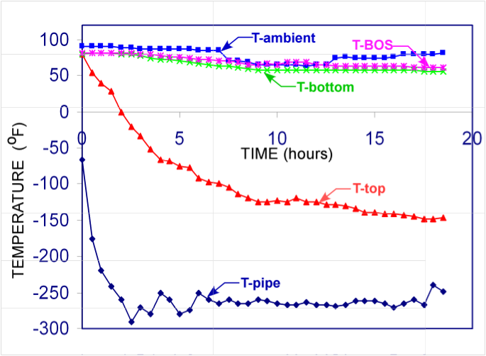
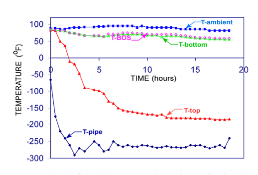
To show the results of temperature and stress analysis in three pipe support shoes intended for cryogenic operation

It is necessary to know the temperature distribution for cryogenic conditions because most steels lose ductility as the temperature decreases from normal operating conditions. That is, the steel becomes more brittle.

Any steel structure will have local areas of high stress. This may be caused by, for example, sharp corners in the design, or by inclusions in the material. At normal temperatures the material in the region of these concentrations will yield, redistributing the load locally. Typically these have no significant effect on the integrity of the structure as a whole. In brittle materials, the material cannot yield, so the only alternative is for it to form a crack. Frequently, once the crack has been formed, it will propagate at the approximate speed of sound until it reaches the end of the part, thus causing a catastrophic failure.

Further complicating the picture is the fact that the tendency for brittle fracture increases with part thickness, and this increase is temperature dependent. Clearly, temperature is a critical variable in selecting steels for cryogenic applications.

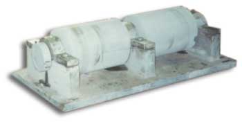
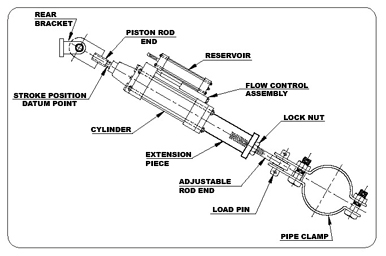
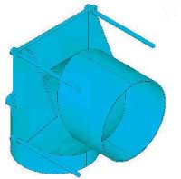
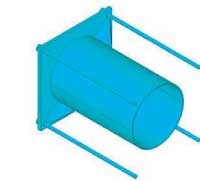
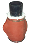
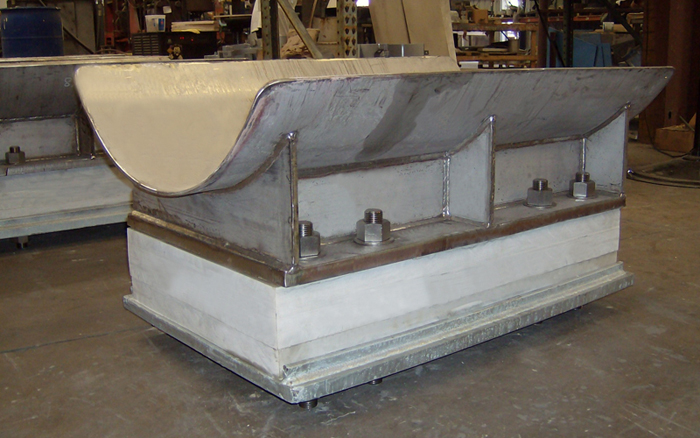
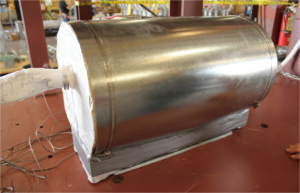
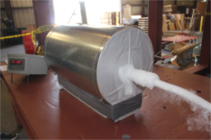
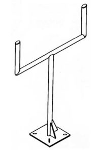
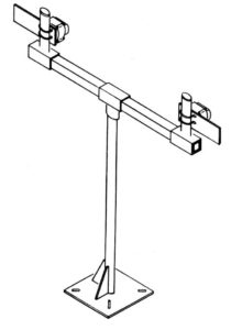
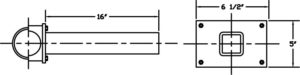
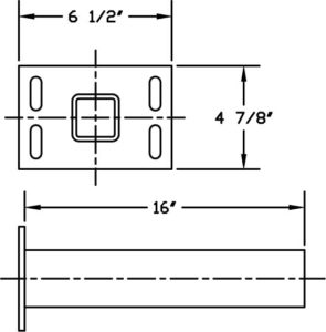
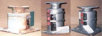
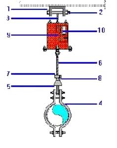
The three shoes considered are of the same basic design, but are for three different pipe sizes: 6, 20, and 42 inch. The basic design is shown in Figure 1.

Image Of A 3D Rendering Of A Complete Pipe Shoe Assembly

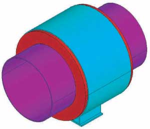
Figure 1: Complete pipe shoe assembly

The shoes have three major components. They are:

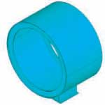
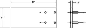
1. An outer cover and base of carbon steel, shown in Figure 2A. This has ring stops at either end to engage the insulation to keep it from moving. A point of particular concern was the temperature and stress of the steel on the inner surface of this ring.

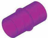
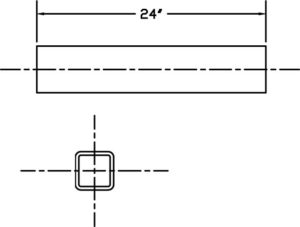
2. A pipe which carries the cryogenic fluid. This has an attached ring of stainless steel, again for engaging the insulation. This is shown in Figure 2B.

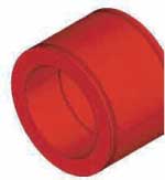
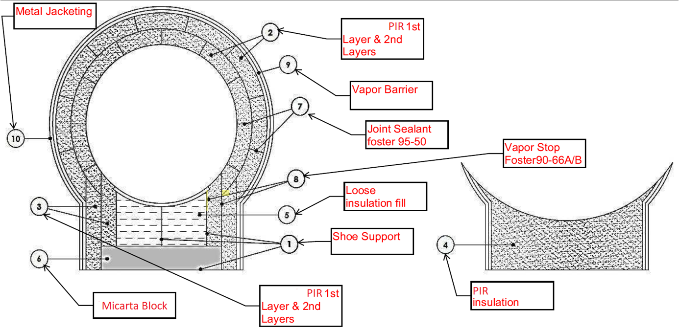
3. The polyurethane foam insulation (PUF) between the first two parts, shown in Figure 2C. As illustrated, the insulation has outer grooves for the shell ring stops, and an inner groove for the pipe ring.

Image Of A 3D Pipe Shell.
Image Of A 3D Pipe And Ring.
Image Of 3D Pipe Insulation.
Figure 2A: Shell
Figure 2B: Pipe and Ring
Figure 2C: Insulation

STRESS & THERMAL ANALYSIS

The stress and the thermal analyses are, for the most part, quite similar. The finite element program, Ansys was used for both. There are two main differences between the analyses. Primarily, the material properties are different. Young’s modulus vs. thermal conductivity, for example; the other main difference is in the choice of elements. In this case we used Ansys element 92 for the stress analysis, and thermal element 83. These are both 10 node tetrahedral solid elements. The primary difference is that the thermal element has only one degree of freedom at each node (for temperature), while the stress element has three, one for x, y, and z displacements.

STRESS ANALYSIS

The main concern in the 42 inch pipe shoe case was the inner surface of the outer retaining rings. If the temperature is too low for the stress, the specified steel may not be appropriate according to the code.

The other two cases are very similar to this one and those stress results are given in Appendix A.

Applied loads for all three cases are given in Table1. Note that while the loads were specified in kN, the actual computations were done in inches and pounds, and the results are reported in those units.

Table 1: Applied loads for the stress analysis of the three shoes

Pipe Size
Axial Load
Vertical Load
Lateral Load
42 in
600 kN
175 kN
70 kN
20 in
275 kN
65 kN
50 kN
6 in
43 kN
25 kN
10 kN

Image Of A Fea On A Pipe Shoe Assembly.

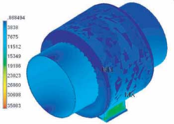
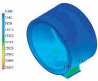
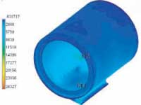
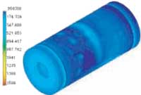
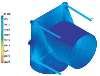
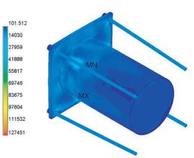
Figure 3: Stresses in the complete assembly for the 42″ pipe shoe
(It is more informative to view the stresses on the individual components)

STRESS ANALYSIS

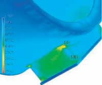
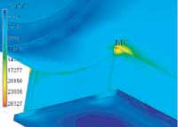
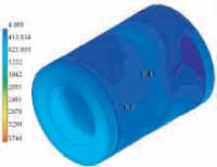
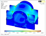
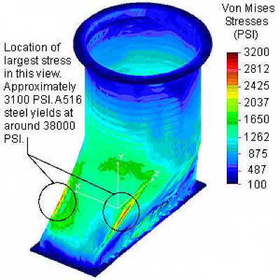
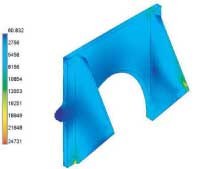
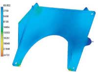
Figure 4 shows an overview of the stresses on the shell and base, and Figure 5 shows a detail of the stresses in the area of maximum stress. The stresses in the shell are generally quite low. However, at the intersection of the base with the cylindrical shell there is a local stress concentration with somewhat higher stresses. This should not be a problem at this location. As we shall see, the temperature here is quite high, as compared to the rest of the shoe.

Image Of An Fea On The Stresses For A Pipe Shell And Base.
Image Of An Fea In Detailed View For The Pipe Base.
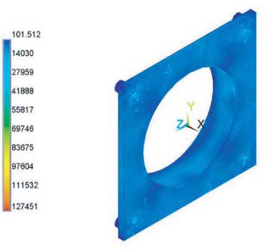
Figure 4: Stresses in shell and base
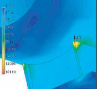
Figure 5: Detail of stresses in the
location of maximum stress

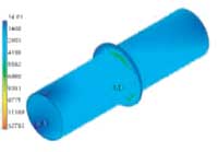
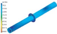
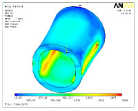
The stresses in the pipe and its ring are shown in Figure 6. The stresses are largest where they would be expected, at the intersection of the two.

Image Of A Fea On The Stresses For A Pipe And Its Ring.

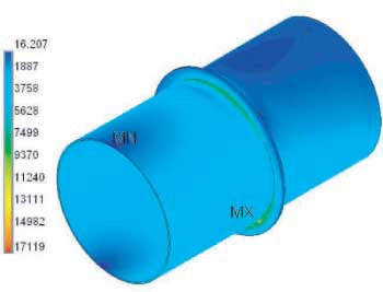
Figure 6: Stresses in the pipe and its ring

STRESS ANALYSIS

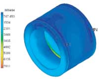
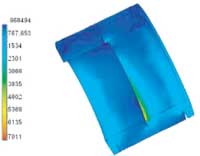
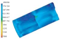
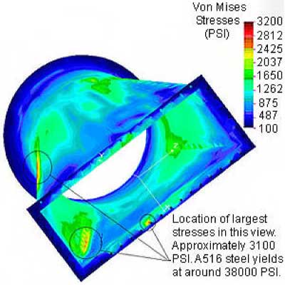
In Figures 7 and 8 we show the stresses in the insulation. Figure 7 is an overview. Figure 8 is a cut away view showing stresses on the inside. The fact that the stress is mostly in the bottom quarter is the result of the significant vertical load.

Image Of An Fea On Pipe Insulation.
Image Of An Fea Done On A Section Of Pipe Insulation
Figure 7: Stresses in the insulation
Figure 8: Section detail of insulation stresses

THERMAL RESULTS

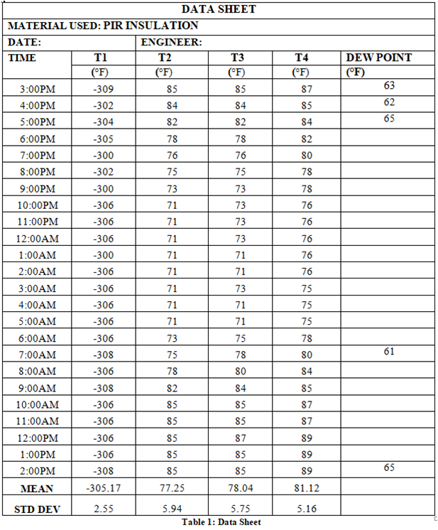
For all three shoes, the thermal conditions were the same. The inner surface of the pipe was -270°F. The ambient air temperature was -20°F, with a wind velocity of 78.74 in/sec (2 m/sec). Based on this wind speed, and the diameter of the outside shield, we computed a film heat transfer coefficient. The values for the three cases are shown in Table 2.

Table 2: File heat transfer coefficients used in the study

Pipe Size
Coefficient
42 in
0.008281 BTU/ in2 hr
20 in
0.009651 BTU/ in2 hr
6 in
0.01190 BTU/ in2 hr

The values of thermal conductivities used are in Table 3. Note that for the 32 lb PUF case the coefficient is linear with temperature. For the 20 Lb PUF we had only one data point, so we were unable to use a temperature dependent relation.

Table 3: Thermal conductivities for materials used in the study

Material
Conductivities in BTU /hr in oF
Carbon Steel
2.645
Stainless Steel
0.7846
32 Lb PUF
.0.003007-0.000003627*T

TEMPERATURE DISTRIBUTION

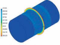
In Figure 9 we show the temperature for the complete assembly. As expected, the temperature on the pipe is the specified temperature, and the temperature on the base is slightly lower than the ambient.

Image Of An Fea On The Complete Pipe Shoe Assembly.

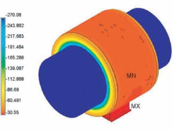
Figure 9: Complete assembly (°F)

Again, it is helpful to look at the individual parts. Figure 10 shows the temperature on the shell and base. The coldest temperature is greater than -40°F, and thus much higher than the temperature that would cause concern.

Image Of Fea Done On The Shell Base Assembly.

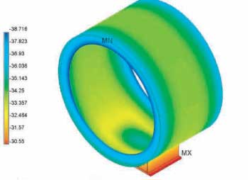
Figure 10: Shell-base assembly (°F)

TEMPERATURE DISTRIBUTION

In Figures 11 and 12 we show the temperature distributions on the other two parts. There is nothing particular to note concerning these plots. (Temperatures are °F)

Image Of An Fea Done A Pipe And Ring.
Image Of Fea For Pipe Insulation.
Figure 11: Ring and Pipe
Figure 12: Insulation

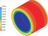
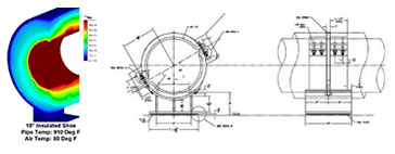
Figure 13 shows the interface between the steel and the insulation. As expected, the temperature in both the inner and outer rings is little affected by the temperature in the surrounding insulation, and is nearly the same as if there were no insulation present.

Image Of Fea Done On A Sectional View Of A Pipe Support Assembly.

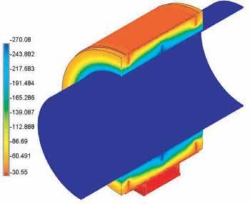
Figure 13: Section view showing interface between the steel and insulation

The report includes both the temperature and the stress at each point of the shoe assembly. This should be adequate for a proper selection of steels for the design.

APPENDIX A

In this Appendix we show the results of the stress analyses of the 20 and 6 in. pipe cases. There is little to add to what has been said about the 42 in. case.

Fea On Stresses In 20&Quot; Assembly.

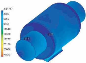
Figure A1: Stresses in 20 inch assembly
Fea On The Stresses In Shell-Base Part.
Fea On The Detail Of Maximum Stress
Figure A2: Stresses in shell-base part
Figure A3: Detail of maximum stress
Fea On The Stresses In Shell-Base Part.
Fea On The Detail Of Maximum Stress
Figure A4: Stresses in ring pipe
Figure A5: Stresses in insulation

Fea Of A Cut Away View On Insulation Stresses

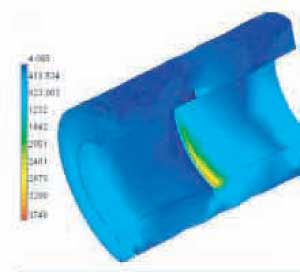
Figure A6: Cut away view of insulation stresses

Fea On The Overall Stresses On 6 Inch Assembly

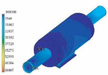
Figure A7: Overall stresses on 6 inch assembly
Fea On The Shell-Base Stresses For 6 Inch Case
Fea In Detail At The Maximum Stress
Figure A8: Shell-Base stresses, 6 inch case
Figure A9: Detail at maximum stress
Fea On The Stresses In Pipe And Ring.
Fea On The Stresses In 6 Inch Insulation
Figure A10: Stresses in pipe and ring
Figure A11: Stresses in 6 inch insulation
Fea On The Detial Of The Ring
Fea On The Stresses On Insulation Section
Figure A13: Detail of ring
Figure A12: Stresses on insulation section

At the left, we show a expanded view of the ring – pipe intersection. The high stresses shown in Figure A10 are very local, and only near the pipe end. This is where the loads were applied. The total load is correct, and, as can be seen, stresses near the intersection are more moderate.

APPENDIX B: Temperature Distribution

Note: Temperatures are degrees °F

Fea On A Complete Assembly For 20 Inch Pipe Shoes

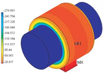
Figure B1: Complete assembly for 20 inch pipe shoe

Shell Base Assembly For 20 Inch Pipe Shoe

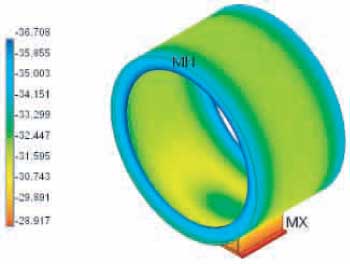
Figure B2: Shell-base assembly for 20 inch pipe shoe

Fea On The Pipe-Ring Assembly For 20 Inch Pipe Shoe

Figure B3: Pipe-ring assembly for 20 inch pipe shoe

Fea On Insulation Block For 20 Inch Pipe Shoe

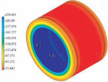
Figure B4: Insulation block for 20 inch pipe shoe

Cut Away View Of Insulation Block For 20 Inch Pipe Shoe

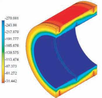
Figure B5: Cut away view of insulation block for 20 inch pipe shoe

Fea On Pipe Shoe Assembly For 6 Inch Pipe Shoe

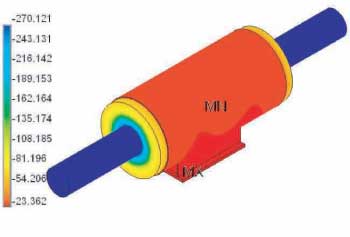
Figure B6: Pipe shoe assembly for 6 inch pipe shoe

Fea On Shell-Base Assembly For 6 Inch Pipe Shoe

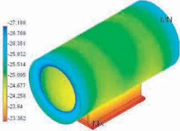
Figure B7: shell-base assembly for 6 inch pipe shoe

Fea On Pipe-Ring Assembly For 6 Inch Pipe Shoe

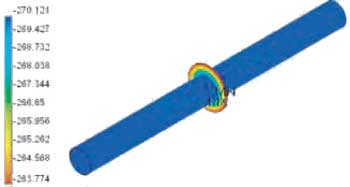
Figure B8: Pipe-ring assembly for 6 inch pipe shoe

Fea On Insulation For 6 Inch Pipe Shoe

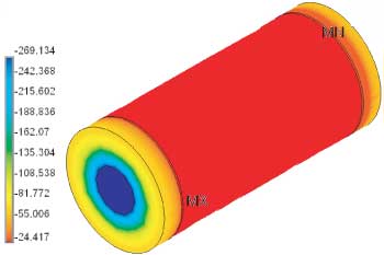
Figure B9: Insulation for 6 inch pipe shoe
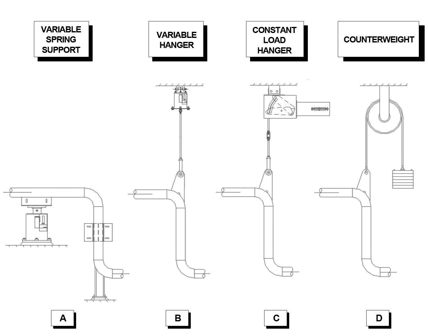
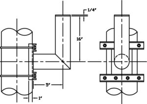
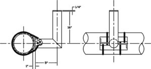
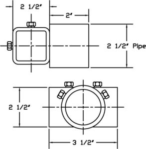
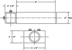
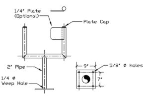
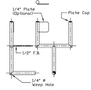
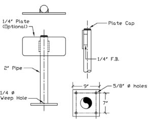
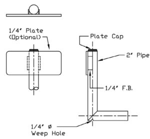
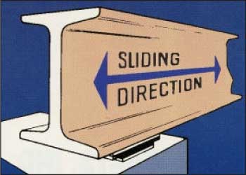
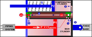
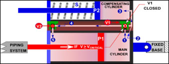
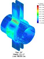
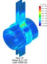
Analysis of a Frictional Constraint

Download PDF

Pipe Clamps

PT&P manufactures a range of standard clamps covering common pipe sizes. These are made of carbon steel and either galvanized or left black. In addition, we frequently fabricate custom clamps for special applications. Applications examples include high temperatures requiring alloy steel, or those requiring nonstandard dimensions.

In these analyses, we have assumed that the bending radius of forming the ears is 1.5 times the plate thickness. This is the value calculated and used as a practice at PT&P. The AISC recommends that the values are three times the thickness of the plates of 1 to 1-1/2” thickness and four times the thickness for greater thickness. The Finite Element Analysis demonstrates that larger radiuses would result in lower stresses. These cases prove that Finite Element Analysis at PT&P has led to significantly lower costs to our customers by justifying the use of less steel.

FEA & Specially Designed Clamps

Recently, a stress analysis was conducted of an 82 plastics pipe constrained in the axial direction by a special pipe clamp. PT&P’s final design assumes that three clamps in a series will resist at a total expected axial force of 8,000 lbs. Since the area of the pipe in contact with the support affects the overall stress distribution, it is necessary to determine how much contact there is at different pressures via FEA in two steps.

Step #1

The first step establishes whether or not the stresses in the clamp and pipe

Fea On A Pipe Clamp.

were in acceptable limits and fixes a starting condition for the remainder of the analysis. Here, the clamping force (estimated to be 13,300 lbs.) alone acted upon the clamp and pipe. The initial design of the clamp indicated stresses exceeding permissible boundaries by being greater than 50,000 psi. The design was thus modified to alleviate the problem.

Step #2

This step involves determining the highest load achieved before slipping.

Fea On A Pipe.

Figure 1 shows stresses on the complete assembly and points that the maximum stress on the clamp is 28,800 psi. The high stress is localized in very small areas at the tip of the gusset. In Figure 2, we have plotted stresses in the plastic pipe only. The maximum stress in the pipe is an acceptable 2,360 psi.

Summary

The maximum stress on the clamp is determined to be 28,800 psi. Stresses in Figure 1 would normally be of little concern in mild steel at typical operating temperatures. If it were a problem, extending the gussets upwards is recommended. In addition, it is recommended to increase pipe length if higher stress is desired. This is due to increased contact between the pipe and clamp, which spreads stress over more area allowing for greater pressures.

Exploring Plate Thickness

Download PDF

Pipe Clamps

PT&P manufactures a range of standard clamps covering common pipe sizes. These are made of carbon steel and either galvanized or left black. In addition, we frequently manufacture custom clamps for special applications. Examples of such applications are high temperatures requiring alloy steel, or applications requiring nonstandard dimensions.

PT&P normally analyzes such special designs using Finite Element Analysis. One reason for this is to ensure that the design has sufficient strength to support expected loads. This is also done to see if the clamp can be made more economically and still function satisfactorily.

FEA & Specially Designed Clamps

Recent examples include two Figure 80 type clamps for a high temperature application. Figure 80 clamps are heavy-duty three-bolt pipe clamps. Due to the high temperature duty, they were made from alloy steel, A387 Grade 91. This steel contains 9% Chromium, 1% Molybdenum and small amounts of Niobium and Vanadium. Both clamps are for 24” pipes, one for a load of 68,200 lbs., and one for 33,500 lbs.

Results: Clamp Test #1

The initial FEA was conducted on the clamp designed to sustain a load of 68,200 lbs. For this load, the PT&P Clamp Sizing program called for a clamp made from two 2” thick x 12” wide strips of steel. This case required the FEA find a maximum stress of 6150 psi. This is considerably less than
the allowable stress for the steel at the operating temperature. As a result, the clamp thickness was reduced to 1-1/2“. It was confirmed that the stresses were again below the allowable.

Image Of Fea Done For Plate Thickness.

12 x 2” Clamp for 24” pipe with load of 68,200 lbs

Results: Clamp Test #2

The second FEA was conducted on a clamp designed for a load of 33,500 lbs. According to PT&P’s standard sizing program, this clamp’s design was made from 1-1/2” x 10” steel. The FEA found a maximum stress of 4250 psi, well below the 10,300 psi allowable. Thus, PT&P engineers reduced the size of the clamp to 1-1/4” x 8”, with resulting stress of 7331 psi.

Image Of Fea Done On Plate Thickness

1-1/2 x 10” Clamp for 24” pipe with a load of 33,500 lbs

Conclusions

In these analyses, we have assumed that the bending radius of forming the ears is 1.5 times the plate thickness. This is the value calculated and used as a practice at PT&P. The AISC recommends that the values are three times the thickness of the plates of 1 to 1-1/2” thickness and four times the thickness for greater thickness. The Finite Element Analysis demonstrates that larger radiuses would result in lower stresses. These cases prove that Finite Element Analysis at PT&P has led to significantly lower costs to our customers by justifying the use of less steel.

FEA on a Transition Piece

Download PDF

FEA: Case Studies

Product: Transition Piece

Technical Information: 3D Modeling Software, Parametric Technologies Modeler, Finite Element Analysis Software, COSMOS
Image Of An Fea On A Transition Piece
Case Study Information

This item was modeled to the specifications included in drawing 6819001-159020. It uses a standard flange at the top as specified. It has been modified to include the extra length of pipe and to eliminate two flanges. The rectangular flange is fabricated of 1.25 x 5 inch stock and is made of A36 steel. The whole transition and pipe is fabricated of 3/8” thick A516 Grade 70 steel and this was expressed in the model. The model has a temperature condition of 105° C/221°F.

Two cases were modeled in which all references to pressure, PSI, refers to PSIG (PSI gage). The first was at operating condition when the transition piece experiences 18.7 PSI internal pressure. The second was at full vacuum when the transition piece experiences 15 PSI external pressure. The stress and displacement results are expressed in the following plots.

*Note: All references to pressure, PSI, refers to PSIG (PSI gage)

Illustration of Pressures and Displacements – Transition Piece: Internal Pressure = 18.7 PSI

Pressures And Displacements On The Transition Piece

Stress Plot #1 – Transition Piece: Internal Pressure = 18.7 PSI

Fea Showing The Largest Areas Of Stress.

This model has an internal pressure of 18.7 PSI on every internal surface. The chart on the left of the model shows the stresses at every point in the model by a color coding system.

Stress Plot #2 – Transition Piece: Internal Pressure = 18.7 PSI

Fea Showing The Internal Pressure On The Transition Piece

This model has an internal pressure of 18.7 PSI on every internal surface.

Displacement Plot #1 – Transition Piece: Internal Pressure = 18.7 PSI

Fea Showing The Internal Pressure At 18.7 Psi

This model has an internal pressure of 18.7 PSI on every internal surface. The chart shows the displacement at every point in the model by a color coding system which represents inches of displacement.

Illustration of Pressures and Displacements – Transition Piece: External Pressure = 15 PSI

Pressures And Displacements On The Transition Piece At 15 Psi

Stress Plot #1 – Transition Piece: External Pressure = 15 PSI

Fea On The Transition Piece At 15 Psi.

This model has an external pressure of 15 PSI on every external surface. The chart above shows the stresses at every point in the model by a color coding system.

Stress Plot #2 – Transition Piece: External Pressure = 15 PSI

Fea On The Transition Piece At 15 Psi

The chart above shows the stresses at every point in the model by a color coding system. This model has an external pressure of 15 PSI on every external surface.

Displacement Plot #1 – Transition Piece: External Pressure = 15 PSI

Fea On The External Pressure Of The Transition Piece At 15 Psi

The chart above shows the displacement at every point in the model by a color coding system which represents inches of displacement.

FEA on Duel Hinged Expansion Joints

Download PDF

Objective

Stress analysis was performed on a dual hinged expansion joint to determine whether the plate thicknesses are sufficient to insure that the stresses are within code allowable.

Portion Of A 36 Inch Bellows Assembly
Figure 1. Portion of a 36 inch Bellows assembly (EJ-004)
Portion Of A 18 Inch Bellows Assembly
Figure 2. Portion of a 18 inch Bellows assembly (EJ-009)

Figures 1 and 2 show a portion of a similar dual hinged expansion joint that was built by U.S. Bellows, Inc. The figures show the connection of the tie rods to the bellows. The tie rods are connected to a plate-gusset assembly, which is welded to the bellows. This note describes a stress analysis to determine whether the plate thicknesses are sufficient to insure that the stresses are within code allowable.

Parameters

Table 1. Parameters of the two tie rods supports analyzed.
Tag
EJ-004
EJ-009
Bellows Diameter 36 in 18 in
Plate Dimensions 46 x 46 x 2 in 24 3/4 x 24 3/4 x 1 in
Tie Rod Diameter 1 in 1 in
Gusset Thickness 3/4 in 3/8 in
Load per Tie Rod 19,297 lbs 5,443 lbs
Steel A240 tp304H A240 tp304H
Bellows Operating Temp. 1076 oF 1076 oF
Allowable Stress 10 ksi 10 ksi

Ansys Finite Element Program

The analysis was done using Ansys Finite Element Program. The element used was the Ansys solid 187 element, a 10 node tetrahedral element.

The results for EJ-004 are shown in Figures 3, 4, and 5. Figure 3 shows the stresses in the complete assembly.

Von Mises Stresses For Complete Assembly.
Figure 3. Von Mises Stresses for complete assembly.
Stresses in the Plate
Stresses In The Plate-Gusset Assembly.
Figure 4. Stresses in the plate-gusset assembly of EJ-004 (Front View)
Stresses In The Plate Gusset Assembly
Figure 5. Stresses in the plate-gusset assembly of EJ-004 (Back View)

The stresses on the assembly are all nearly below the allowable. There are two small areas where there are stress concentrations, but the areas are small, and the stresses drop rapidly away from the peak. These local areas should not be of concern.

Stresses in EJ-009 Assembly
Stresses In The Complete Assembly

Figure 6. Stresses in the complete assembly for EJ-009

Figure 6 shows the stresses in the complete portion of the assembly analyzed. There are some quite high stresses shown. These are in the pipe at the tip of the guests. They are clearly due to very large change in stiffness at that point, – from 3/8 in. in the pipe to 1 7/8 in. at the tip of the gusset.

Stresses On The Tie Rod Plate
Figure 7. Stresses on the tie rod plate for EJ-009

Figure 7 shows the tie rod support plate. The stresses are all clearly below the allowable. In conclusion, the thickness of both plates analyzed are adequate.

High Temperature Furnace Seal Bag

Furnace Bag

Openings between the floor of the furnace and the pipe penetration openings can cause heat energy loss in certain types of furnace applications. A penetration bag type seal is now available to prevent energy loss through the pipe penetrations during the expansion and contraction movement of the pipe through the furnace floor. The use of a furnace seal bag permits movements of the pipe through the furnace floor while providing an airtight closure to prevent heat loss.

Application
PT&P’s furnace seal bag works similar to a fabric expansion joint. The bag, consists of multiple layers of flexible, flame and heat resistant, impervious fabric designed to operate from start-up to high-temperature design conditions. The bag contracts and expands with varying furnace temperatures. The seal bag allows thermal expansion and prevents the loss of heat through the furnace floor which conserves energy and reduces the cost of energy.

Furnace Sealing Bags Prior To Installation

Furnace Sealing Bag After Movement &Amp; Temperature Tests
Components
Stainless steel clamps or band straps connect one end of the pipe that goes through the penetration opening and the other to another sleeve in the furnace floor. A tapered steel coil is installed around the conduit inside the bag to prevent the fabric from collapsing inward during vacuum conditions. PT&P’s standard furnace seal bag is nickel reinforced, with a special coating that reduces airborne fibers and increases tensile strength.
Components Of A Furnace Bag Application
This type of furnace seal is a cost-effective solution to a problem with potentially high-energy losses. The seal can function through maintenance ‘shut-down’ cycles and is easily replaced after several years of operation. Furnace bags may also be customized to suit any specifications for unique design needs.

Bellows Fatigue Testing

Top