Every operationally sound piping system, from oil fields to chemical plants, relies on foundational components to maintain integrity and function. Among the simplest of these supports is the U-bolt. While they may appear basic, U-bolts are the key anchors that provide essential stability, restrain movement, and protect your valuable piping assets.
The Mechanics of the U-Bolt: Function and Design
The U-bolt is named for its distinctive “U” shape, which, when installed, wraps around the pipe and is secured to a support structure with two nuts. This design serves two primary functions in piping infrastructure: support and restraint.
The Primary Role: Stabilizing and Supporting Pipe Runs
In its most common application, a U-bolt acts as a simple hanger or support. It transfers the weight of the pipe, the fluid inside, and any insulation to the structural element (such as a girder or foundation) to which it’s fastened. Holding the pipe firmly against a saddle or resting surface prevents downward movement and maintains precise elevation.
The Secondary Role: Lateral Restraint and Guiding
U-bolts are highly effective as pipe guides or restraints. When a pipe experiences dynamic forces, such as high winds, seismic activity, or internal vibration from pumps and flow, the U-bolt prevents lateral (side-to-side) and axial (along the pipe’s length) shifting. This is crucial for:
Preventing Damage: Stopping the pipe from rubbing against adjacent structures or equipment to prevent costly wear and abrasion.
Controlling Movement: Guiding the pipe to ensure that any necessary thermal expansion or contraction occurs in the intended direction, preventing excessive stress on nozzles and connections.
U-Bolts in Action: Critical Considerations for Installation
While U-bolts are versatile, proper selection and installation are vital to prevent long-term damage to the pipe.
Protecting the Pipe: The Importance of Anti-Friction Pads
A common issue with bare metal U-bolts is metal-to-metal contact with the pipe. Over time, vibration and movement can cause the bolt to wear through the pipe coating or even the pipe wall itself: a condition known as crevice corrosion or pipe wear. To prevent this, industry best practice often requires the use of:
Polymer Pads (e.g., HDPE or PTFE): Installed between the U-bolt and the pipe to act as a barrier, absorbing vibration and preventing abrasion.
Rubber/Elastomer Lining: Used for quieter systems or in applications where vibration dampening is paramount.
Material Selection: Matching the Environment
The harsh environment of industrial facilities dictates careful material choice. For standard dry environments, galvanized carbon steel may suffice. However, in applications with high humidity, chemical exposure, or extreme temperatures, stainless steel (304 or 316) U-bolts are necessary to ensure corrosion resistance and structural integrity over decades of service.
Engineered U-Bolts for Exceptional Performance with PT&P
At Piping Technology and Products, we recognize that even the simplest components require precision engineering. We provide high-integrity solutions that withstand the most demanding industrial environments.
Our goal is to elevate the performance of foundational components. We ensure the long-term integrity and reliability of your entire piping system by delivering custom-manufactured U-bolts and supports that meet your exact specifications for material, load capacity, and corrosion resistance, eliminating the risks associated with inadequate, off-the-shelf components.
We offer:
Custom Sizing and Threading: U-bolts designed for non-standard pipe diameters and complex geometries.
Exotic Materials: Fabrication using specialty alloys for extremely high-temperature or highly corrosive services.
Integrated Solutions: Providing the U-bolt complete with the correct saddle, pad, and coating for a guaranteed non-abrasive, high-performance installation.
Don’t gamble your infrastructure on generic U-bolts.Contact Piping Technology and Products today to secure your system with U-bolts and supports engineered for absolute reliability and a longer lifespan.
The integrity of a piping system is only as good as the stress analysis that proves its design. For engineers responsible for plant safety and compliance, selecting the right software is the most critical step.
While many tools exist, three industry titans consistently lead the conversation in pipe stress analysis (PSA): CAESAR II, AutoPIPE, and CAEPIPE.
We’ll compare these leading solutions, providing an overview of where each excels so you can make an informed choice that guarantees both compliance and reliability.
CAESAR II Pipe Stress Analysis Software
AutoPipe Pipe Stress Analysis Software
Software Comparison Table (CAESAR II, AutoPIPE, CAEPIPE)
Feature / Software
CAESAR II (Hexagon)
AutoPIPE (Bentley Systems)
CAEPIPE (SST Systems)
Market Position
Widely considered the industry standard and market leader with the most extensive user base.
A major competitor, it is powerful due to its integration with the Bentley ecosystem.
Known for its ease of use, fast analysis, and intuitive interface.
User Interface / Modeling
Spreadsheet-based data entry combined with a 3D graphical modeler. Highly detailed and robust.
Object-oriented, CAD-like graphical interface (point-and-click modeling) is often cited as highly intuitive.
Clean, multi-window interface providing simultaneous visual and textual feedback.
Key Differentiator
Extensive Code Compliance: Supports the most international codes and standards, such as ASME B31.1 Power Piping, ASME NC & ND Boiler and Pressure Vessel Code.
Optimization & Interoperability: Includes a Support Optimizer (AI/Machine Learning) and deep integration with Bentley/3D CAD products (STAAD.Pro, OpenPlant).
Speed and Simplicity: Emphasis on fast solution times and a minimal learning curve for quick productivity.
Advanced Analysis
Static, dynamic, vibration, fatigue, wind, seismic, and wave loading.
Fluid Transient (Water Hammer), buried pipe analysis with upheaval, and Flange analysis.
Random vibration (PSD), Force Spectrum Analysis, detailed Fatigue calculations (Steinberg’s Method).
Integration
Good integration via PCF, PDS, and other formats.
Excellent interoperability with Bentley products and other major CAD systems (SmartPlant, Aveva PDMS/E3D).
Strong data import/export from major 3D design software (AutoCAD Plant 3D, PDMS).
CAESAR II is the veteran and remains the benchmark. Many consulting and EPC firms use it as their default tool, and it is a common requirement in job postings. Its strength lies in its long history and unmatched depth of code libraries.
AutoPIPE is widely used by organizations already operating within the Bentley ecosystem (using tools such as MicroStation or OpenPlant). Its seamless integration with structural analysis software (STAAD.Pro) is a significant advantage, enabling a combined piping and structural analysis workflow.
2. Modeling Philosophy: Spreadsheet vs. Graphics
CAESAR II often requires more upfront data entry in a spreadsheet format, which some veteran users prefer for its precision and structure.
AutoPIPE and CAEPIPE are often praised for their modern, CAD-like graphical modeling, which features point-and-click functionality, significantly reducing the learning curve and speeding up initial model creation and modifications. CAEPIPE, in particular, emphasizes a simple, intuitive user interface for rapid modeling.
3. Advanced Features and Niche Analysis
AutoPIPE Advanced stands out with tools like the Support Optimizer, which uses machine learning to quickly evaluate thousands of support configurations, helping engineers optimize support costs and placement—a huge win for large projects.
CAESAR II has a strong focus on compliance and is highly robust in general dynamic and vibration analysis.
CAEPIPE is well-regarded for its fast nonlinear analysis (gaps and friction) and specialized tools for random vibration, making it a favorite in industries like aerospace and nuclear, where rapid, complex analysis is critical.
Choose Piping Technology & Products(PT&P)
PT&P is the physical link between your pipe stress analysis and guaranteed field performance.
We specialize in translating complex load reports and displacement results from CAESAR II, AutoPIPE, and CAEPIPE into precisely engineered pipe supports and expansion joints: ensuring the reliability calculated in your software model becomes a reality in your plant’s operation.
Your software has calculated the loads: now let’s secure them. Click here to get a custom quote for supports that validate your stress analysis and guarantee long-term system integrity.
If you manage a process plant, power facility, or oil and gas operation, you know that piping systems are at the center of your entire operation. But how often do you think about the hidden forces: the intense pressures, temperature shifts, and vibrations that are constantly pushing your pipes to their breaking point?
Ignoring these forces isn’t just a risk; it’s a guaranteed path to costly downtime, failures, and safety hazards. This is where pipe stress analysis comes in: it’s the essential engineering practice that ensures your piping system not only works but lasts.(more…)
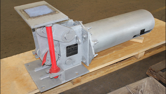
Constants use a spring coil (or series of coils) to accommodate pipe movement from the initial (installed) condition to the final (operating) condition of the piping system. For all constant spring supports, there is no difference in load, and the supported load will remain uniform throughout the deflection cycle.
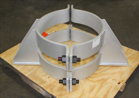
PT&P designed and fabricated a U-Type constant spring support , with PTFE and a 25% glass-filled side plate for a polypropylene plant in Texas. The constant is fabricated from carbon steel and hot-dipped galvanized for extra protection against corrosion. The vertical movement is 1.5″ total upward travel and is capable of supporting a load of 10,350 lbs. throughout its range of movement. The constant underwent standard load testing prior to shipment.
Along with chemical plants, constant spring supports are utilized in refineries, power plants, and heat recovery steam generators (HRSG). The design of the constant spring support replaced a system of pipe support called a “counterweight” design still used in some facilities today. The counter-weight system utilized pipe clamps or lugs (attached or welded to the pipe), cables, pulleys, and a set of weights. Just like the old-fashioned brass weighing scales, weights were added to one end of the pulley system until an equilibrium was reached. The counterweight design needed a large amount of space with which to operate. Constant spring hangers replaced this system because they require much less space in order to function (similar to some designs we stand on to weigh ourselves). No matter the application, our team of experienced engineers and designers can help to resolve your pipe support needs. Please contact us via our 24×7 emergency service or send an email to [email protected].
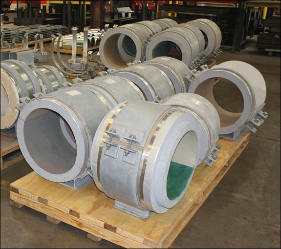
Insulated pipe supports are designed to prevent direct heat transfer between pipes and their supports. Thus, they prevent heat loss due to conduction at each support. Whether a cold or hot temperature pipeline, the transfer from cold to hot or hot to cold is prevented. They serve the following purposes: Carry the load and allow necessary movement (when used with slide plates) at each point of support, provide insulation in the support area where the regular pipe insulation is not sufficient to support the load, and minimize installation costs by reducing the time required to install the support. The supports are not welded to the pipe, and each unit is shipped completely assembled (except for the riser supports and anchor supports, both of which require some welding). In HVAC and plumbing applications, insulated supports also help prevent condensation and corrosion under insulation (CUI) by maintaining the vapor barrier at the support point. Their use contributes to better energy performance, reduced maintenance, and compliance with MEP design standards focused on energy efficiency and moisture control in building systems.
For this project, we custom-designed 98 insulated pipe supports for an ammonia project at a chemical plant in Louisiana. The supports were designed for both cryogenic and high-temperature pipe systems, with an 8″ to 22″ baseplate width and a 10″ to 28″ saddle length. They were designed for pipe diameters of 6″-24″ and are composed of polyurethane foam for cryogenic and high-density calcium silicate insulation for high temperatures. Standard Q.C. and dimensional tests were performed prior to shipment.
This project was a combination of upgrading a current anhydrous ammonia plant and adding new capacity to the facility. We worked with the EPC, on-site contractors, and operators to ensure specifications and delivery deadlines were met over a three-year period during project construction. In addition to the insulated supports discussed here, we designed, manufactured, and shipped bellmouth reducers, metallic expansion joints, pipe shoe guides and anchors, pipe hanger hardware, slide plates, snubbers, sway braces, struts, and variable spring supports.
Beyond ammonia and chemical processing facilities, insulated pipe supports are widely used across other industries where thermal control and system integrity are essential. These include petrochemical plants, LNG and cryogenic gas facilities, power generation plants, and district energy systems for heating and cooling networks. They are also integral to MEP infrastructure in data centers, pharmaceutical manufacturing, and food processing plants, where preventing condensation and maintaining precise temperature control are critical. In each of these applications, insulated supports help maintain energy efficiency, protect against corrosion under insulation, and ensure long-term reliability of piping systems operating under extreme temperature conditions.
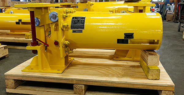
We custom-designed multiple horizontal F-Type constant spring supports for a series of offshore gas platforms located in the Persian Gulf, near the coast of Saudi Arabia. These constants feature stainless steel slide plates and are engineered for a total travel of 17.5 inches. Fabricated from carbon steel, they are hot-dipped galvanized and coated with a specialized three-layer paint system to withstand the harsh, highly corrosive environment. Per the client’s specification, the topcoat is painted “Safety Yellow” for easy identification.
To further enhance corrosion resistance, the bolting assemblies used in constructing these units were coated with a fluoropolymer, which also helps to reduce friction and wear. Each assembly measures 24 inches in height and ranges from 36 to 87 inches in length. They are designed to operate at temperatures up to 250°F and handle loads of up to 13,500 pounds. Load testing and dye penetrant inspections were performed in-house to ensure quality and reliability before shipment. Our manufacturing is based on a long test and reliability work methodology, with our roots in engineering and design when we started as a pipe stress company. In addition to manufacturing the products our customers design for their specific applications, we also conduct testing to meet both our quality standards and their requirements.
F-type constants manage loads, thermal compensation, vibration dampening, and vertical and lateral movements in piping systems. We have supplied constants for a myriad of end applications worldwide. The industries we have worked with that need this kind of product in their piping systems include:
Energy and Oil & Gas
Chemical and Petrochemicals
Renewable Energy and Sustainability
Industrials and Manufacturing
Automotive
Semiconductor
Pulp and Paper
Utilities and Power
Construction and Building Materials
We have optimized our manufacturing process to offer an unparalleled range of customization options with minimal impact on delivery timelines. In addition to our standard (hot-dipped galvanized carbon steel with neoprene-coated spring coils) constant spring supports, we can customize any material, finish, dimension, load, load adjustment, travel, and travel stops, as well as provide sensors for remote monitoring.
Historically, obtaining a custom-designed constant spring support posed a significant challenge in terms of both design and manufacturing, with lead times extending to a minimum of 6-8 weeks.
Through a dedicated focus on manufacturing optimization and employing a design-centric engineering approach, we have reduced the required manufacturing time by more than half. The process of acquiring custom constant spring supports is now significantly streamlined. In fact, we are capable of fulfilling emergency orders in less than 24 hours, taking into account the client’s location and urgent requirements.
We can also provide the services of our well-trained field service teams for installation guidance, should it be needed.
At our Houston-based facility, we design and manufacture constant spring supports with unmatched speed and precision. Operating 24/7, we are equipped to handle both small emergency orders and large-scale production needs. Our wide range of industry expertise demonstrates our unique ability to provide solutions across the globe in every sector we serve.
Your pipeline is the circulatory system of your operation, and just like a human body, it requires routine maintenance to function at its peak.
In chemical and petrochemical industries, pigging systems are used to separate different products within a pipeline to prevent contamination, as well as for cleaning and inspection. In water and wastewater treatment, they help remove sediment, biofilms, and scale from municipal mains to improve water quality and flow efficiency. In the food and beverage sector, pigging is employed to reclaim valuable products and prevent cross-contamination when transporting different batches of liquids such as chocolate, dairy, or juices. Similarly, in pharmaceuticals and cosmetics, pigging is applied in sanitary processes to clean and inspect pipelines, ensuring product purity and compliance with strict hygiene standards.
Pigging: the act of using a device called a “pig” to clean, inspect, or maintain a pipeline, is the most effective way to achieve optimal performance from your piping operation. And at the center of any successful pigging program is the pig launcher.
A pig launcher is a specialized piece of equipment that safely introduces a pipeline pig into a pressurized line. It’s a critical component that delivers efficient and safe pigging operations.
Choosing the right one is important. This guide will help you understand the benefits and options available, enabling you to make an informed choice that will aid in maintaining a debris-free piping operation.
Equipment
The physical infrastructure is essential for any pigging operation. This equipment, including pig launchers and receivers, enables the safe and efficient introduction and removal of pigs from the pipeline.
Pig Launcher: An oversized section of pipe where a pig is loaded and then launched into the main pipeline. It’s equipped with a quick-opening closure for easy access and various valves to control pressure and fluid flow.
Pig Receiver: Located at the end of a pigging run, this is a similar oversized section of pipe designed to catch the pig and any debris it pushes. It also features a quick-opening closure for retrieving pigs and debris.
Kicker and Bypass Lines: The kicker line is a smaller pipe that directs a portion of the product flow into the launcher to propel the pig. Bypass lines are used in receivers to allow continuous product flow while the pigging process is underway.
Why Pig Launchers Are Important for Your Piping Operation
Investing in a quality pig launcher isn’t just about maintenance; it’s about safeguarding your assets and maximizing your return. The benefits extend far beyond a clean pipe:
Boosted Productivity and Flow: Debris, wax, and scale buildup inside pipelines can restrict flow, increase friction, and reduce overall throughput. Regular pigging removes these blockages, improving flow rates and boosting operational efficiency.
Reduced Operational Costs: By recovering valuable products, minimizing waste, and decreasing the need for extended shutdowns for manual cleaning, pigging systems can lead to significant cost savings.
Increased Safety: Modern pig launchers are designed with safety features, such as quick-opening closures and pressure relief devices, to protect personnel and equipment during operations, thereby mitigating risks associated with high-pressure systems.
Product Batching and Separation: For companies that transport different products through the same pipeline, pigging allows for the effective separation of batches, preventing cross-contamination and ensuring product purity.
For a deeper dive into how custom solutions can address specific challenges, read our companion piece:Custom-Designed Pig Launcher.
Your Options: Choosing the Right Pig Launcher
Pig launchers are not one-size-fits-all. They are highly customized based on your specific application, pipeline dimensions, and operational needs. Here are the key factors you need to consider:
Sizing and Pressure
The most important considerations are the size of your pipeline and the operating pressure. The launcher’s major barrel must be large enough to hold the pig, while the minor barrel must match the diameter of the pipeline. Our capacity for design pressure range is up to 4000 PSIG (pounds per square inch gauge) for pig launchers and receivers:
Material Selection
The material of the launcher is critical for lifespan, application, and media integrity . Most are fabricated from carbon steel, but for corrosive or sanitary/food grade applications (e.g., food and beverage/pharma), materials like stainless steel are often required to prevent contamination and withstand harsh environments.
Level of Automation
Pig launchers come with various levels of automation. From simple, manually operated systems with flag indicators to fully automated, remotely controlled units, the choice depends on your budget and the frequency of pigging operations. Automated systems reduce operator involvement, increase safety, and enable more frequent and aggressive pigging programs.
Things We Need to Know, Before We Quote a Pig Launcher or Receiver
What will the launcher be used for, liquid or gas? This will determine the design code.
What will be the pressure and temperature of the fluids in the operating system?
Will you need supports (legs) to be included?
What type of finish will you select? The standard finish is our shop primer.
Do you have any special requirements? Anything added to a launcher or receiver can increase both complexity and cost.
What is the location of closure, where the pig will be loaded? As pressure requirements increase, closure options become more restrictive.
Specialized Features
To optimize your system, consider these options:
Quick-Opening Closures: These are essential for safe and rapid access to the launcher barrel, allowing for the insertion or retrieval of the pig.
Instrumentation Ports: These allow for pressure monitoring, while vents and drains are crucial for depressurization and cleaning.
Bypass Lines: A bypass allows product flow to continue while the launcher is offline for maintenance.
Multiple-Pig Systems: For complex operations, launchers can be designed to hold and launch multiple pigs in sequence, which is ideal for multi-stage cleaning or intelligent inspection.
At Sweco Fab, a Piping Technology & Products company, we offer the following capabilities for pig launchers and receivers:
Fabrication Design Codes
Materials of Construction
Design Pressure Range
Pig Trap Size Ranges
Maximum Overall Skid Offered
Shop Certifications
ASME B31.4, B31.8, B31.4 & Sec. VIII Div.1
CS, LTCS, SS 304, SS316 & API Pipes
Up to 4000 PSIG Line
2″ NPS to 48″ NPS Lines
8′ x 40′ x 10′ (Up to 40,000 Lbs weight capacity)
ASME U & R Stamp certified, ISO 9001
Don’t Leave Your Pipeline to Chance: Partner with Piping Technology & Products (PT&P)
Every pipeline is a significant investment, and its performance directly impacts your bottom line. By selecting the right pig launcher and receiver system, you can ensure continuous operation and protect your infrastructure. The decision to pig your pipeline is the first step toward a smarter, more profitable operation. The next step is choosing a partner like PT&P who can provide the right solution, tailored to your exact specifications.
Ready to boost performance and safety in your pipeline operations? Contact our experts and request a quote today to design a custom pig launcher.
PT&P is Now ISO 9001:2015 Certified (09-05-2015)
Piping Technology & Products, Inc. is awarded the ISO 9001:2015 certificate by DNV Certification, a division of Det Norske Veritas (DNV), for the Manufacture of Hot and Cold Pipe Supports. This certificate proves that PT&P’s Quality Management System has been certified against the best practice standard and is compliant.
The latest version of standards, ISO 9001:2015 is created by the International Organization for Standardization (ISO), who set international requirements for Quality Management Systems. By conforming to the Quality Management System, Piping Technology & Products, Inc. demonstrates predictability of internal operations and the ability to meet customer requirements. While becoming certified, a company can identify the areas that are most critical to operations through management system audits. Once problem areas are identified, measured, managed and improved, customer satisfaction will rise, staff responsibility and motivation will also experience growth.
When vertical piping in a high-pressure system starts to shift, everything downstream is at risk. Hanger misalignment, accessory failure, and field delays would be the least of your worries when vertical pipe systems experience axial displacement.
That’s where Piping Technology & Products’ custom riser clamp assemblies deliver assurance engineers can count on. With the proper design specifications, PTP can manufacture precision riser clamps that ensure secure and reliable product delivery.
Purpose-Built for Vertical Load Control
Riser clamp assemblies are specifically engineered for vertical pipe systems where axial movement must be restricted. It is not a one-size-fits-all product. Each assembly is fabricated to fit exact pipe diameter, temperature, and load specifications, most commonly for critical process lines in synthetic gas, petrochemical, or tall vertical rack applications.
At its core, the assembly relies on a heavy-duty steel clamp secured around the pipe, working in tandem with thrust plates to manage axial loads.
For high-heat applications, manufacturers utilize A387 alloy steel (rated for service temperatures of 750°F to 1,000°F) and a high-temperature coating that won’t degrade or flake under scorching conditions.
Once installed, the clamp limits movement in the downward direction, ensuring the pipe doesn’t slip under load or due to temperature expansion. Engineers often pair the clamp with spring hangers or sway struts for a complete load path solution.
Real-World Application: Synthetic Gas Plant Retrofit
At the request of a synthetic gas facility, PTP engineered a custom riser clamp assembly for their high-temperature vertical piping. We used Alloy A387, a heat-resistant steel specifically selected for service temperatures reaching up to 1,000°F, to fabricate this assembly.
To ensure performance under thermal cycling, we coated the clamp with a high-temperature industrial-grade coating designed to withstand prolonged exposure without degradation. By preventing vertical slippage during system startup, the clamp maintained alignment integrity and eliminated the risk of early rework or other types of damage to the pipeline.
Common Use Cases for Riser Clamp Assemblies
Riser pipe clamp assemblies serve a critical role in applications where vertical piping must be securely supported and restrained.
Engineers commonly use them on vertical risers in fired heater loops, where high temperatures and axial loads demand reliable restraint. They also support tall structural pipe racks in petrochemical plants, ensuring alignment across multi-level piping systems.
In high-rise and offshore environments, riser clamps provide secure anchoring for firewater systems subject to seismic or dynamic loading. Additionally, LNG facilities rely on them for vertical steam lines that require thermal movement control and long-term integrity.
Key Benefits for Field Execution
PT&P’s custom riser clamp assemblies provide clear advantages for vertical piping systems.
They prevent pipe slippage by firmly securing the line in place, ensuring axial stability under load.
Each assembly is custom-sized to match the exact pipe outer diameter, specified load, and temperature range, eliminating fit-up issues during installation.
PT&P designs these supports to handle pipe sizes up to 48 inches and fabricates them with high-temperature materials and coatings that perform reliably in scorching environments.
Engineers apply Finite Element Analysis (FEA) to optimize steel thickness, reduce excess material, and validate structural integrity.
By managing design, fabrication, and delivery in-house, PT&P minimizes handoffs and reduces the risk of delays or errors throughout the supply chain.
Why Engineers Choose Riser Clamp Assemblies
Engineers value this clamp for its precision and structural integrity. Load ratings are validated through FEA, ensuring that the clamp can stand against almost any surprise event. For jobs with elevated temperatures or non-standard loads, our custom approach removes guesswork from spec compliance.
Why Project Managers Chose Riser Clamp Assemblies
What sets these clamps apart is how they minimize scope creep.
When clamp assemblies are properly designed from the start, there’s no field modification, no install surprises, and fewer RFIs. The result: less rework, better schedule control, and a clear value add during procurement planning.
Other Items Often Purchased with Riser Pipe Clamp Assemblies
When engineering systems for extreme low-temperature applications, managing thermal contraction and heavy structural loads is critical. In trunnion support piping, a specialized trunnion support is often welded directly to the piping, such as at a base elbow (ell), to provide a robust anchor or resting point.
Unlike standard pipe shoes, trunnions offer exceptional structural stability by distributing the load across a larger, reinforced surface area of the pipe wall. This design reduces localized stress and improves overall system reliability, particularly in high-load applications.
For cryogenic and low-temperature service, trunnion supports must be properly insulated using high-density polyurethane or similar materials. This insulation is essential to prevent thermal bridging, minimize moisture ingress, and avoid ice formation, all of which can compromise system performance and integrity.
Whether used as a static support or integrated with alignment devices such as a trunnion positioner, custom-engineered trunnion assemblies provide a reliable solution for maintaining structural integrity and safe operation in demanding industrial environments.
What is a Trunnion Pipe Support?
A trunnion pipe support is a structural component used to support a piping system and is connected directly to the process line. It functions as a secondary pipe element, helping hold the main line in position for stability. ASME standards guide their application and analysis to ensure safety and reliability, particularly in high-energy piping and under various operating conditions.
In standard applications, trunnions are used to:
Support sections of pipe vulnerable to weight or stress
Help manage pressure at directional changes like elbows
Provides added stability and structural strength by helping reinforce the system at critical load points
Prevent displacement under heavy loads or external forces
In cryogenic systems, however, added challenges emerge. Maintaining thermal insulation at support points is critical. Without it, heat transfer through the support could lead to the evaporation of liquids into gases, cause condensation, and/or result in ice buildup. Over time, this can damage the pipe or disrupt flow.
Custom Trunnion Base ELL Pipe Supports for Cryogenic LNG Applications
Trunnions Designed with Insulation for an LNG Facility
At an LNG gasification facility, our customer required pipe supports that could prevent the transfer of heat and provide trunnion-like stability and strength. Piping Technology & Products collaborated closely with the client to design a customized solution that met both mechanical and thermal performance requirements.
The result was a trunnion base ELL support with a layered construction: an A36 carbon steel base, an integrated insulation block, and a stainless steel pipe saddle. This configuration prevented heat transfer between the pipe and the support.
By incorporating an insulation block into this design, we prevented heat transfer from the trunnion pipe support to the process line, which is a feature that a standard trunnion does not offer. The trunnion keeps the cold pipe separated from warmer support steel, suppressing frost build-up at the base and pipe rack. The pre-insulated support design maintained a steady temperature for the LNG from Point A to Point B, preventing it from warming up and converting from a liquid into a gas.
What Is a Trunnion Base ELL Support and How Does It Work?
A trunnion base ELL support for LNG applications is a specialized insulated pipe support designed for cold-service and cryogenic process lines. It supports the main pipe while creating a thermal break between the pipe and the support base.
Unlike standard trunnions, which are not designed to address thermal integrity, this design minimizes thermal bridging.
It typically uses:
A carbon steel base for structural strength
A block insulation layer to isolate temperature
A stainless steel pipe saddle that connects to the process pipe
Where Trunnion Base ELL Supports Are Used
Trunnion base ELL supports are specifically designed for cold-service environments where thermal performance is critical.
They are commonly used in LNG liquefaction and gasification facilities, where maintaining sub-zero temperatures is essential to system operations and safety. These supports also play a key role in ethylene and ammonia plants, which use chilled piping to move process materials while minimizing energy loss.
In all cases, the design enables operators to move product from one stage to the next without experiencing temperature changes, condensation, or structural complications caused by frost buildup.
Key Field Benefits
Thermal isolation is built in; it prevents cold pipe surfaces from transferring extreme temperatures to structural steel, helping maintain safe operating loads without added field insulation.
Reduces condensation, prevents ice formation, and pipe damage
Custom-fit to specification for pipe sizes ranging from 2 in. to 60 in., fitting cleanly into the line
Supports heavy vertical loads while preserving pipe wall integrity
Material matched to the parent pipe to maintain mechanical and chemical compatibility
Delivered fast, often within weeks, even for custom builds
Provides rigid support in low-movement areas, preventing pipe sag or collapse in static runs or where line displacement is minimal.
Helps reduce stress at elbows and vertical transitions, reinforcing piping in high-pressure or structurally sensitive locations.
Why Engineers Choose Trunnion Base ELL Supports
Engineers specify trunnion base ELL supports when thermal isolation is non-negotiable. These supports are sized according to the process pipe’s outside diameter and insulation thickness, ensuring a proper interface without modifying the pipe’s thermal envelope.
The materials used, including carbon steel (for areas not in direct contact with the process line), high-performance insulation, and stainless steel, are known to perform reliably in environments that reach as low as -300°F.
Why Project Managers Trust It
Project managers rely on trunnion base ELL supports to avoid the common pitfalls that delay cold-service projects. Because the insulation is integrated into the support design, there’s no need to coordinate separate insulation crews or handle last-minute RFIs about support height or fit-up.
Eliminating this extra field work speeds up installation, lowers labor coordination complexity, and reduces the risk of frost-related damage during startup. By arriving job-ready and material-matched, these supports enable faster handoff to commissioning teams and help keep the schedule on track.
Why Choose Piping Technology for Your Cryogenic Pipe Supports
We deliver custom-engineered cryogenic pipe supports built to meet the exact demands of cold-service environments.
Our in-house team manages the entire fabrication process, from material selection to final delivery, providing you with tighter control over schedule and quality.
For complex or high-load applications, we can perform Finite Element Analysis (FEA) to verify stress points and optimize steel thickness for performance and safety. With decades of experience and a proven track record in LNG, ammonia, and ethylene systems, we provide both the technical expertise and manufacturing speed your project requires.
Q: Exactly what is a trunnion in the context of pipe supports?
A: In industrial piping, a trunnion support is a cylindrical projection—typically a secondary section of pipe welded directly to the main pipe or elbow—that serves as a structural attachment point or resting base for a support. It provides a stable interface for transferring loads from the piping system to the supporting structure.
Q: How does a trunnion pin function within an industrial assembly?
A: A trunnion pin acts as a central pivot point or load-bearing axle within an assembly, allowing connected components to rotate or accommodate movement. This helps reduce stress on the system while maintaining structural stability and proper alignment during operation.
Q: Are trunnion bearings required for all trunnion installations?
A: Not always. For static support applications, trunnions may simply rest on a steel base or slide plate. However, in dynamic applications, trunnion bearings or specialized bearing-trunnion designs may be used to reduce friction and allow for smooth rotational or lateral movement during thermal expansion and contraction cycles.
Q: How is a trunnion bolt used in these support systems?
A: A trunnion bolt is a heavy-duty fastener used to securely anchor the support assembly or its structural housing to the surrounding steel framework, ensuring the piping remains locked in its designated position under massive operational loads.
Q:Does the concept of a trunnion apply to pipeline valves as well, such as a trunnion valve ball?
A: Yes. In a trunnion valve ball design, the internal ball is supported by top and bottom trunnions (shafts), which anchor it in place. This design absorbs line pressure and significantly reduces the operating torque required to open and close the valve compared to a standard floating ball valve, improving performance and reliability in high-pressure applications.