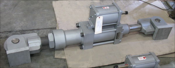
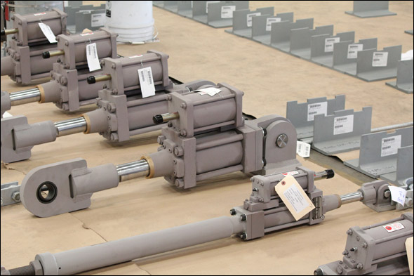
Fronek Anchor/Darling Enterprises, a division of PT&P designed and fabricated hydraulic snubbers for a geothermal facility in California. The Fig. 510 AD snubbers ranged in size from 34-3/4″ to 37-5/8″ piston-to-piston and were designed for a 50,000 lb. maximum load, 5″ cylinder size and a 6″ stroke. The Fig. 511 AD snubbers ranged in size from 56-15/16″ to 59-5/16″ P-P and were designed for a 20,000 lb. maximum load, 2-1/2″ cylinder size and a 6″ stroke. Hydraulic snubbers are designed to protect the piping system when a sudden, heavy load is applied (such as an earthquake of high intensity), which can cause serious vibrations leading to complete destruction. A custom three-bolt pipe clamp fabricated from carbon steel was designed to fit in a limited space. A cycle test throughout the full stroke from zero to fully extended was performed prior to shipment.
Read MoreBlog
7 Ways to Extend the Lifespan of a Hydraulic Snubber
Follow these 7 steps below to maintain and extend the life span of your hydraulic snubber.

1. Observe the fluid level to make sure there is sufficient fluid for the snubber to operate
2. Check for leaks – If the fluid level is decreasing, determine the cause and effect remedial action.
3. Check the condition of the load pins and spherical ball bushings. Apply a high pressure grease for long-term benefits.
4. Check the condition of the exposed portion of the piston rod. Check for scoring, paint or other physical damage.
5. Check the condition of the piston rod wiper. Verify that it’s in position and working effectively.
6. Check for evidence of abuse like welding arc strikes, bent or dented parts, scratched paint, etc.
7. Finally, check the overall physical appearance. This encompasses all of the above.
Read More
Variable Springs with Guided Load Columns and PTFE Lined Pipe Saddles
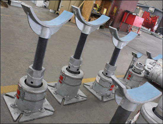
These F-type variable spring supports are fabricated from carbon steel with a hot dipped galvanized finish and designed with guided load columns to provide stability for minimum lateral movement. The fig. 46 pipe saddles are also fabricated from carbon steel with a HDG finish and lined with PTFE, 25% glass filled material. The pipe saddles are designed for 8″ to 36″ diameter pipe sizes, and the entire assembly is 50″ in height. These variable-saddle support assemblies are capable of supporting up to 22,300 lb. and 1″ vertical movements. We performed standard spring loading tests and a Q.C. inspection prior to shipping to an offshore oil and gas platform near Malaysia.
Read More

