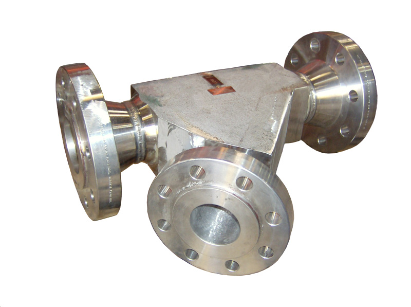
This sway strut is fabricated from carbon steel and measures 240″ from pin to pin. The pipe is 6″ in diameter and has a load capability of 15,000 lbs. The components were completed with a hot-dipped galvanized finish, and the pipe was coated with a shop primer. The function of a sway strut is to restrain the movement of piping in one direction while providing for movement due to thermal expansion or contraction in another direction.
This particular sway strut will support a 30″ process line in a refinery. This type of support is necessary because the current line has only a few I-beams for support. Additionally, the I-beams that support the line are very high off the ground and not capable of handling the large forces acting on the line. Due to the loads acting upon the pipe and the length of the required strut, a heavy schedule pipe and a heavier-duty strut ends were necessary.
Do you require sway struts in your plant or refinery? Get pricing today!
These pipe shoes are fabricated from A-516 GR70 carbon steel. PTFE, 25% glass filled material, is bonded to a carbon steel plate, then welded onto the shoe to allow movement of the pipe during expansion and contraction. The pipe shoes range in size from 18″ to 28″ in width and 28″ to 43″ in length.
Want to learn more about pipe shoes? Instantly view a webinar today!
43″ Angulating Constants for a Power Plant in Utah
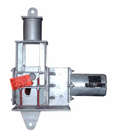
The design of this constant requires that it be connected by pins from the top and from the bottom to allow it to angulate. The constant assemblies are fabricated from A36 carbon steel. The constants measure between 23″ and 43″ in length with a take-off between 29″ and 55″. The load range is 60 lb. to 2,605 lb. and each constant assembly underwent standard load and travel testing.
Do you see a need for constants in your plant or refinery? Get pricing today!
Spider Guides for a Heat Recovery Steam Generation Plant Spider Guides
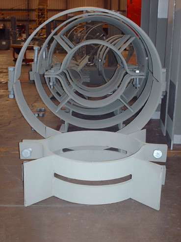
Components of these Cylinder Pipe Guides (a.k.a. Spider Guides) include carbon steel plates, stock clamps, angles, and hot-dipped galvanized pipes. The Guides range in pipe size from 6″ to 16″. The maximum design temperature for the Spider Guides is 750ºF.
They are designed to control lateral pipe movement and maintain the alignment of the piping through its axial and contraction cycles. A single piping run uses multiple Spider Guides to avoid a fulcrum or an imposed lateral deflection on critical components.
Want to learn more about spider guides? Instantly view a webinar on spider guides!
97″ Diameter, 3-Piece Pipe Clamps for a Refinery in Ponca City
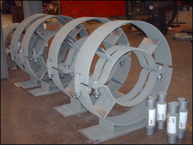
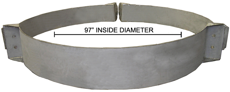
Piping Technology & Products, Inc. fabricated 3-piece pipe clamps used to support 97″ diameter stainless steel duct work. This duct work is being added to a refinery for an expansion project in Ponca City, Oklahoma. Each section of the clamp assembly is formed from a continuous plate and gussets are added at each of the bolt locations for increased strength and rigidity. Due to the ducts having a relatively thin wall, these clamps are designed wider than necessary in an effort to reduce localized stresses on the duct work. The lower section of each clamp is formed to create a 150° cradle. This acts as a cradle by supporting the duct without inducing extra pressure, which might cause the duct wall to buckle or bend.
The upper sections are formed from 1/2″ thick by 12″ wide bar stock, whereas the lower sections are formed from 1/2″ thick by 18″ wide. All three sections are rolled to an inner radius of 48 1/2″ and the welded gusset plates are all 1/2″ thick. The upper sections are formed at 105° each, and the upper load bolt is 2″ in diameter while the six clamping bolts are 1 1/2″ in diameter.
The maximum load to be carried by these pipe clamps is 16,888 lb. Each pipe clamp will be used in conjunction with a variable spring support to accommodate movements as high as 2 1/4″.
Do you require 3-piece pipe clamps for your plant or refinery? Get pricing now!
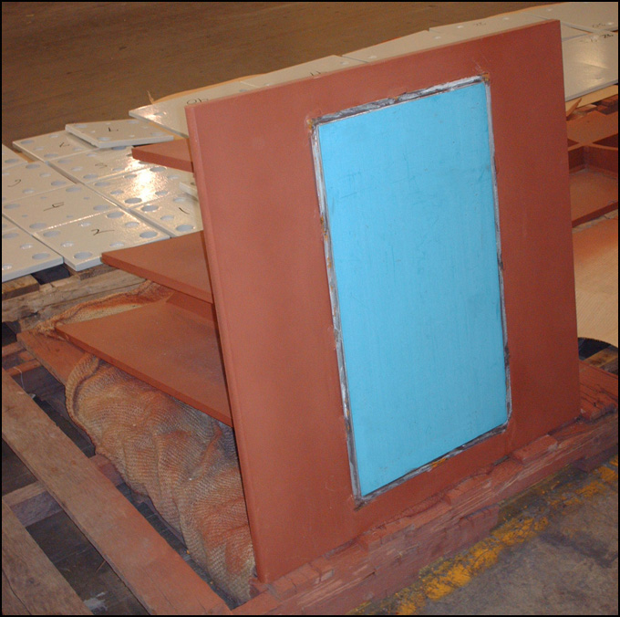
SWECO Fab, Inc. manufactured a pig launcher and receiver used to launch a pig throughout the piping system to clean the pipe line. Both the pig launcher and receiver have been hydro-tested to ensure quality and performance. Multiple coats of paint were also applied for environment protection.
Injection-Molded Anchors for an LNG Plant6″ NPS Anchors
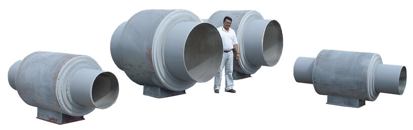
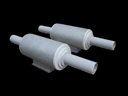
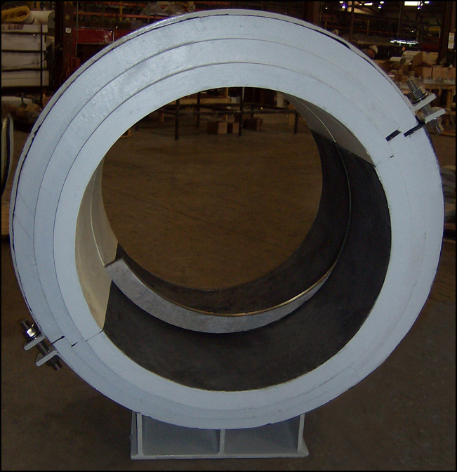
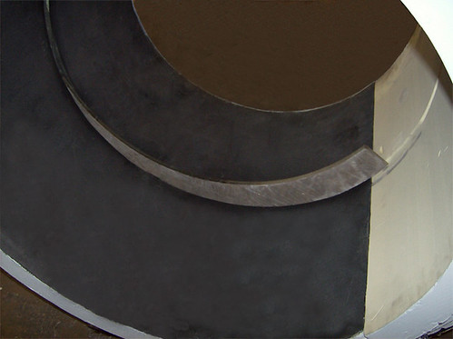
These supports are used in a re-gasification terminal and are designed for -29°C ambient and -196°C fluid temperatures. The polyurethane foam insulation is injected into a mold with a pipe spool in place to ensure maximum fit. The pipe anchors are made from 516 Grade 70-N carbon steel. These supports were put through Finite Element Analysis and inspected by our Quality Control Department.
42″ NPS
20″ NPS
6″ NPS
Axial Load:
136,000 lb.
62,500 lb.
9,773 lb.
Vertical Load:
40,000 lb.
14,773 lb.
5,682 lb.
Lateral Load:
15, 909 lb.
11, 364 lb.
2,273 lb.
Foam Density:
32 lb. PCF
32 lb. PCF
20 lb. PCF
Want to learn more about pre-insulated supports? View a pre-insulated support webinar today!
Cold Insulated Pipe Anchors for an LNG PlantBase Stop
Piping Technology & Products designed and fabricated 36″ diameter insulated pipe anchors that included base stops to prevent lateral and axial movement of the anchor.
The design of the insulated stop plates allows the anchor to withstand 63,000 lbs of axial load. The use of Polyurethane insulation allows for operating temperatures down to -300°F.
Do you require insulated pipe anchors for your piping system? Get pricing today!

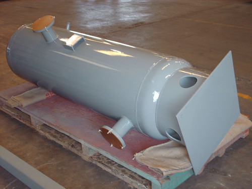 26″ Hot Water Expansion Tank for a Compressor Station
 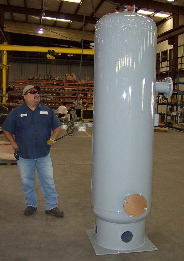 26″ Hot Water Expansion Tank for a Compressor Station