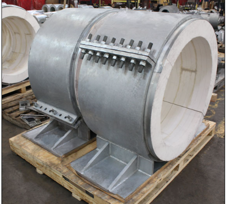
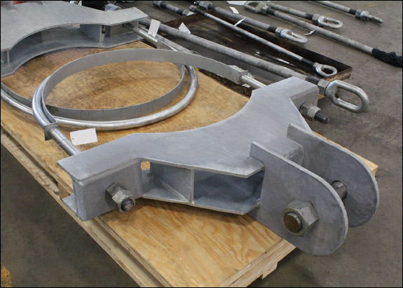
| Type: | Constant Spring Supports |
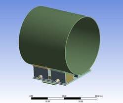
| Size: | 15-¼” W x 17″ H x 46″ L with 9-¼” OD |
| Material: | Carbon Steel | Hot-dipped Galvanized |
| Design: | 2,379 lb. Load | 10″ Upward Movement |
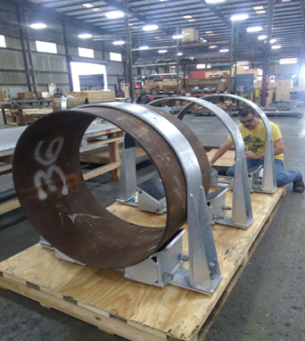
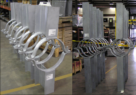
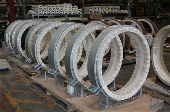
Piping Technology & Products (PT&P) custom-designed and manufactured constant spring supports for a chemical processing facility in Singapore that produces industrial gases such as hydrogen, carbon monoxide, and synthesis gases.
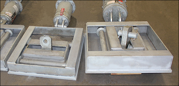
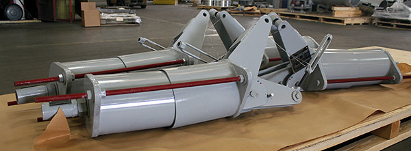
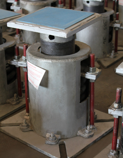
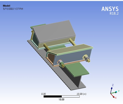
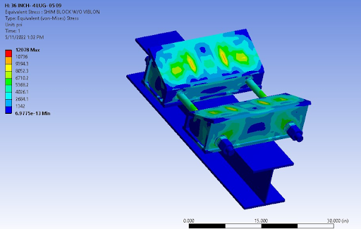
The constant spring assemblies were fabricated from ASTM A36 carbon steel and incorporated alloy steel coil springs. Each unit measured 15¼ inches wide × 17 inches high × 46 inches long with a 9¼-inch outside diameter. The supports were designed to carry an operating load of 2,379 lbs. while accommodating 10 inches of upward movement.
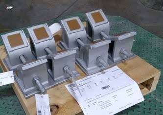
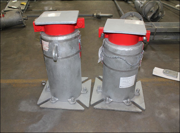
To meet the project’s specific requirements, the constants were engineered with telescoping spring coil housings, allowing the units to accommodate significant travel while maintaining a compact overall design. The assemblies were also coated with a protective paint system to enhance corrosion resistance and extend service life in the operating environment.
Prior to shipment, each constant spring support underwent PT&P’s standard load and travel testing procedures to verify performance and compliance with design requirements. As part of the company’s quality assurance program, every constant spring support manufactured by PT&P is tested before shipment. PT&P maintains an ISO 9001:2015 Quality Management System certified by DNV, ensuring consistent product quality and traceability.
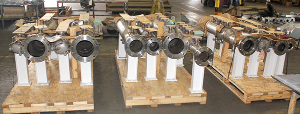
PT&P manufactures more than 1,500 constant spring supports annually, with designs ranging from standard applications to highly customized units capable of supporting loads exceeding 150,000 lbs., and accommodating movements greater than 48 inches.
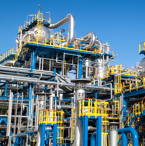
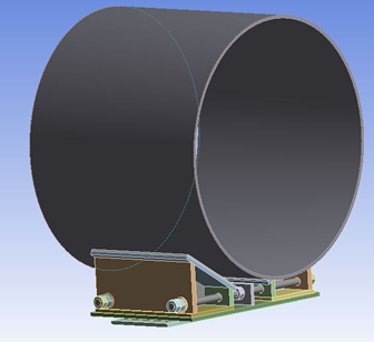
Constant spring supports are widely used in facilities where significant thermal expansion and contraction occur. Typical applications include crude distillation units (CDUs), hydrocracking units, residual fluid catalytic cracking (RFCC) units, naphtha hydrotreaters, hydrodesulfurization units, sulfuric acid regeneration (SAR) units, LNG facilities, geothermal plants, coker units, heat recovery steam generators (HRSGs), chemical processing plants, and other high-temperature industrial systems.
Unlike variable spring supports, constant spring supports are designed to maintain a nearly constant supporting force throughout the entire range of travel. Using one or more spring coils and a mechanical balancing mechanism, they accommodate vertical thermal movement while minimizing load variation on the piping system, thereby reducing stress on connected equipment and structures.
PT&P has developed its manufacturing capabilities to provide extensive customization options with minimal impact on delivery schedules. In addition to standard configurations, constant spring supports can be customized for materials of construction, protective coatings, dimensions, loads, travel ranges, load adjustments, and travel stop configurations.
PT&P REF. ORIGINAL POST 12112018
Read More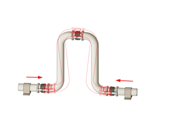

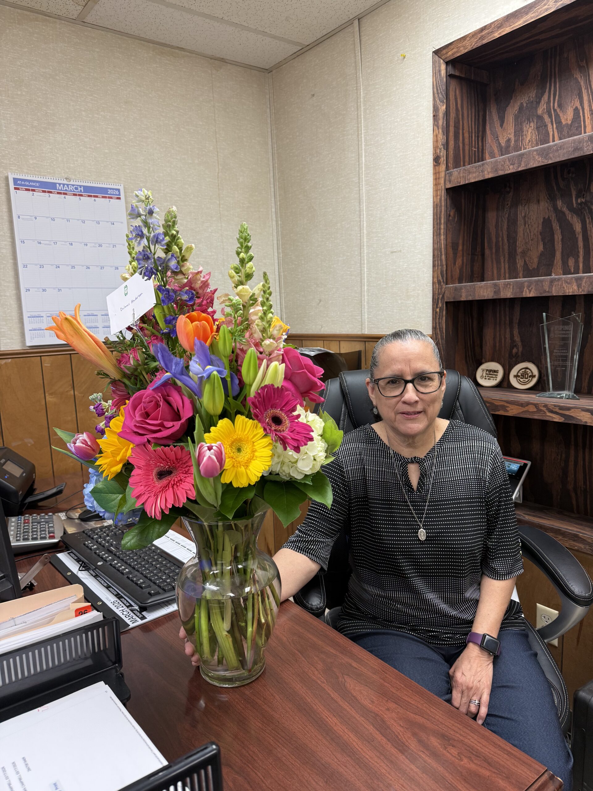 In 1989, when Dolores Anderson walked into Piping Technology & Products’ Long Drive location for her first real job, the accounting office was literally a converted house. The company was smaller, invoices were on paper, and “paperless” wasn’t even a buzzword yet.