The Shift to Liquid Cooling: Powering High-Density Data Centers for the AI Era

January 16, 2026

Pipe Guides from Piping Technology & Products help secure data center servers.

The Shift to Liquid Cooling: Powering High-Density Data Centers for the AI Era

As artificial intelligence (AI) and machine learning (ML) move from niche research projects to the backbone of global enterprise, the data center is facing a thermal crisis. Traditional air cooling, once the industry standard, is reaching its physical limits. Standard racks that previously pulled 10kW to 15kW are being replaced by high-density GPU clusters demanding 50kW, 100kW, or more. To manage this heat flux, the industry is making a decisive shift toward liquid cooling—a medium roughly 3,000 times more effective at heat transfer than air.

Engineering Reliable Piping Systems in Data Center Cooling Systems

The transition to liquid cooling is not a one-size-fits-all migration. It involves sophisticated piping networks that must deliver coolant with surgical precision. Whether a data center facility is being retrofitted or built from the ground up, understanding the three primary cooling methods—and the mechanical infrastructure required to support them—is important for operational reliability.

1. Direct-to-Chip (Cold Plate) Cooling

Direct-to-chip cooling involves circulating coolant through a cold plate sitting directly on the CPU or GPU. This method captures up to 80% of server heat, enabling extreme rack densities while using existing room-level air cooling for the remaining components.

  • The Piping Requirement: High vibration resistance and leakproof integrity.
  • Piping Technology Solution: Custom Engineered Expansion Joints.
  • The Value: In a direct-to-chip setup, the thermal expansion of the secondary loop piping can put immense stress on delicate manifold connections. US Bellows (a PT&P company) provides precision-engineered expansion joints that absorb thermal expansion and mechanical vibration, preventing stress from being transmitted to server racks or sensitive fluid connectors.
2. Immersion Cooling (Single and Two-Phase)

In immersion cooling, servers are completely submerged in a thermally conductive, dielectric fluid. This eliminates the need for fans and allows for the highest power densities available today, as the fluid makes contact with every heat-generating component.

  • The Piping Requirement: Compatibility with dielectric fluids and heavy-load structural support.
  • Piping Technology Solution: Constant and Variable Spring Hangers.
  • The Value: Immersion tanks are incredibly heavy when filled with dielectric fluid. The external piping delivering coolant to these tanks must be perfectly supported to prevent nozzle loading. PT&P’s constant- and variable-spring hangers ensure that, as the system reaches operating temperature, the weight of the piping remains balanced, protecting the integrity of the immersion tanks.
3. Rear-Door Heat Exchangers (RDHx)

An RDHx is a specialized radiator attached to the back of a server rack. Liquid circulates through the door, cooling the exhaust air before it ever enters the data center floor, often allowing for “chilled water-free” operation in certain climates.

  • The Piping Requirement: Precision routing and flexible support in tight spaces.
  • Piping Technology Solution: Pre-Insulated Pipe Supports (Hot/Cold Shoes).
  • The Value: To maintain efficiency and prevent condensation in the white space (main operational area where IT gear sits), coolant lines must be adequately insulated. PT&P’s pre-insulated cold shoes provide a thermal break between the piping and the support structure. This prevents energy loss and eliminates the risk of sweating pipes, which can be catastrophic near high-voltage server equipment.

Why Liquid Cooling is the Ultimate High-Density Solution

The shift to liquid cooling isn’t just about managing heat; it’s about Total Cost of Ownership (TCO) and sustainability within the modern data center.

  • Energy Efficiency: Liquid cooling reduces the Power Usage Effectiveness (PUE) by significantly lowering the energy required for fans and CRAC units.
  • Performance: By keeping GPUs at a lower, stable temperature, data centers can prevent thermal throttling, ensuring AI workloads run at peak performance.
  • Space Optimization: Higher density means more computing power in a smaller physical footprint, deferring the need for costly facility expansions.

PT&P Is Your Partner in Data Center Infrastructure

At Piping Technology and Products, we recognize that a data center’s liquid cooling loop is only as reliable as its weakest support or joint. We position ourselves as the ideal partner for data center operators by offering a unified engineering approach. By manufacturing both the supports that hold the system and the expansion joints that give it flexibility, we provide a holistic mechanical solution that withstands the 24/7/365 demands of critical infrastructure. Our expertise ensures a seamless, safe transition to high-density AI cooling.

Scale Your Data Center Capacity and Optimize for High-Performance Computing

If you are designing a new build or retrofitting an existing center for high-density racks, our engineers are ready to help you optimize your piping support and flexibility: schedule time with one of our engineers to discuss your long-term liquid-cooling strategy.


Read More
Hold-Down Clamps for a Waste Disposal Facility

January 13, 2026

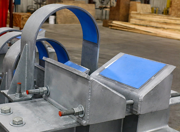
Hold-Down Pipe Clamps for a 20" Pipeline at a Waste Disposal Facility

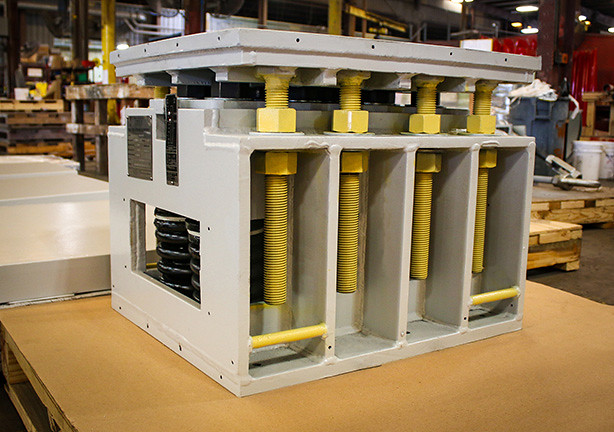
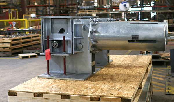
These custom-fabricated hold-down pipe clamps assemblies are designed to effectively control vibration and protect piping systems in demanding industrial environments. Each assembly incorporates wedges made from 25% glass-filled PTFE, which absorb vibration while providing a protective buffer between the steel pipe and the pipe support.

Flow-induced and acoustic-induced vibration are common challenges in Power, Solar, Biofuels, and Chemical plants, as well as in pipelines located near rotating equipment such as reciprocating pumps and compressors. Left unchecked, vibration can lead to cracking, premature failure, and costly unplanned shutdowns. Our engineered solutions help mitigate these risks in both onshore and offshore applications.

The assemblies shown are custom-designed for pipe sizes up to 20″ in diameter and operating temperatures up to 200°F. Adjustable to accommodate a range of elevations from Top of Steel (T.O.S.) to Bottom of Pipe (B.O.P.), each unit measures 21″ wide × 26″ long × 23″ high and has been proven to reduce vibration to acceptable levels.

Fabricated from A36 carbon steel plate with A307 grade all-threaded rods, all components are hot-dip galvanized for corrosion resistance. Every assembly undergoes a thorough quality control inspection prior to shipment—ensuring reliable performance you can trust.

Read More

Managing Vibration in Chilled Water Loops: The Role of Pipe Guides and Anchors in Data Center Cold Piping

January 9, 2026

Liquid cooling in a futuristic data center hallway with glowing blue pipes.

In a data center, chilled water loops are the lifelines that prevent servers from overheating. However, these systems are often subject to intense mechanical stress. Pump-induced vibration and hydraulic shock can lead to resonant frequencies that, if left unchecked, cause metal fatigue, joint failure, and catastrophic leaks.

Achieving mechanical stability requires more than heavy-duty piping; it requires strategically applying pipe guides and anchors to create a controlled environment for fluid transport.

The Critical Role of Anchors and Guides

To stabilize a chilled water loop, engineers must balance two opposing forces: the need for the pipe to move during thermal cycles and the need to keep it rigid against mechanical vibration.

1. Strategic Anchoring: The “Zero Point.”

An anchor is a rigid point of attachment that prevents all translation and rotation of the pipe. In vibration management, anchors are used to:

  • Isolate High-Vibration Equipment: By placing anchors near pumps or chillers, you prevent mechanical energy from “traveling” down the entire piping run.
  • Protect Sensitive Connections: Anchors shield delicate server-row connections from the thrust forces generated by water hammer or pressure surges.

2. Pipe Guides: Directing the Energy

While anchors stop movement, pipe guides are designed to permit axial movement while restricting lateral (side-to-side) and vertical displacement.

  • Preventing Buckling: When a pipe expands, it wants to bow. Guides ensure that expansion is directed straight into expansion joints rather than into the building’s structural steel.
  • Damping Resonance: Properly spaced guides change the natural frequency of the piping system, “breaking up” long spans where vibration could otherwise build into destructive oscillations.

Technical Specifications: Pipe Supports for Stability

To help you identify the most effective hardware for navigating restrictive footprints and structural limitations, the following chart compares the specialized pipe supports used in high-density modernization projects.

Support Type

Best Use Case Mechanical Advantage

Vibration Control

Main Anchor Pump discharge and header turns. Fixes the pipe in all 6 degrees of freedom. Maximum (Stops all transit)
Spider Guide Long straight runs in corridors. Maintains alignment during thermal growth. High (Prevents lateral whip)
Slide Bearings Heavy pipes on secondary steel. Eliminates friction-induced vibration. Medium (Damps surface noise)
Seismic Bracing Critical infrastructure zones. Absorbs sudden high-impact energy. High (Protects against surges)

Protecting Data Center Uptime: A Vibration Control FAQ

How do you stop vibration in chilled water piping? 

To stop vibration, you must install a combination of vibration-isolation hangers near the source and rigid pipe anchors to isolate the equipment. Additionally, installing pipe guides at calculated intervals raises the system’s natural frequency, preventing the buildup of harmonic resonance that can lead to fatigue failure.

Why are pipe guides necessary for expansion joints? 

Pipe guides are essential because they ensure that thermal expansion is directed straight into the expansion joint. Without proper guiding, the pipe may buckle or “squirm” under pressure, causing the expansion joint to fail and the pipe to exert dangerous lateral forces on its supports.

What is the difference between a pipe hanger and a pipe guide? 

A pipe hanger primarily supports the dead weight of the pipe (vertical load), whereas a pipe guide restricts lateral and rotational movement while allowing for axial growth. In high-vibration chilled-water loops, hangers provide support, but guides offer the stability needed to prevent oscillation.

How does improper anchoring affect data center uptime?

Improper anchoring allows mechanical vibration to reach pipe joints and gaskets, leading to “nuisance leaks” or full pipe bursts. In a data center, even a minor leak in a chilled-water loop can cause humidity spikes or direct water damage to server racks, resulting in costly downtime.

Ensure Your System Stability Today

Don’t wait for a hairline fracture to realize your piping system is under-supported. Secure your facility’s future by auditing your vibration control strategy now. Reach out to our engineering team to review your current piping layout.

Piping Technology Data Center Projects Around the Globe
Global map showing the location of Piping Technology & Products’ data center projects, from retrofits to new builds.

How PT&P Adds Value: Improving PUE through Stability

At Piping Technology & Products, we understand that data center efficiency—measured by Power Usage Effectiveness (PUE)—is directly impacted by the health of your cooling loop. Vibrating pipes create turbulence, which forces your pumps to work harder and consume more energy. 

By using our custom-engineered pipe guides and anchors, you minimize mechanical friction and fluid turbulence, allowing your cooling system to operate at peak hydraulic efficiency. Our solutions don’t just protect your hardware; they lower your energy overhead by ensuring that every watt spent on cooling is delivered with precision.

Partner with PT&P to engineer a high-stability, high-efficiency cooling loop for your facility.

Read More

Seismic Bracing, U-Loop Expansion Joints, Pipe Guides, Anchors and Supports: Protecting Data Centers in High-Risk Zones

January 2, 2026

Work with Piping Technology and Products to address differential settlement for your data center in high risk seismic zones.

For data centers and large-scale industrial facilities, downtime is not an option. In high-risk seismic zones, the integrity of cooling and utility piping determines whether a facility survives a geological event or suffers catastrophic failure. Ensuring 100% uptime requires a proactive engineering strategy that moves beyond standard thermal management to address the violent, multidirectional forces of an earthquake.

Drawing on advanced engineering case studies—including massive battery plants with requirements mirroring modern data centers—this post explores how nested U-Loop expansion joints, engineered supports, and rigorous compliance strategies ensure disaster recovery readiness.

The Compliance Imperative: Engineering for Differential Settlement

In seismically active regions, the threat isn’t just the ground shaking; it is the unpredictable movement of the structures themselves. A major compliance challenge in large-scale facilities is “differential settlement,” where one building or section of a facility sinks or settles at a different rate than another.

To remain compliant and operational, piping systems must be designed to absorb these extreme displacements without rupturing. Disaster recovery planning starts at the design phase with pipe stress analysis. For critical infrastructure, it is essential and, many times, a requirement to have Licensed Professional Engineers (PE) stamp both the stress analysis and the design of the expansion joints. This ensures the system can handle specific seismic loads and movements, as well as regular thermal movements.

The Seismic Solution: Nested U-Loop Expansion Joints

Traditional piping solutions often struggle when space is at a premium. While flexible metal hoses are a standard option when space is unavailable, they typically have lower spring rates. They are better suited to smaller, more frequent movements than engineered expansion joints.

To address the dual challenges of seismic resilience and spatial constraints, US Bellows’ breakthrough solution is the first to build U-loops with expansion joints.  Here are some of the advantages and value this custom solution offers data center operators:


  • Hybrid Design: This “industry-first” design integrates bellows directly into the loop structure. This provides superior flexibility to handle both thermal expansion and seismic movement simultaneously without compromising the pipe’s pressure rating.


  • Space Optimization: For crowded jobsites like data centers, “nesting” larger-diameter loops within smaller ones consolidates the hardware. This prevents expansion joints from colliding during seismic shaking, a critical factor in maintaining system integrity.


  • Seismic “Dog Legs”: A dog leg expansion joint is a pipe assembly, typically used in piping systems to compensate for movement from thermal changes or seismic events, using one ninety-degree bends and two straight pipe sections to form an “L” shape. For areas requiring extreme versatility, specialized dog leg expansion joints can handle both lateral and axial movement in both vertical and horizontal orientations.

Pipe Anchors, Guides, and Supports: The Backbone of Cold Piping

Even the most robust expansion joint will fail if the surrounding pipe is not adequately supported. A comprehensive seismic strategy must include durable bracing and specialized guides.


  1. Reducing Anchor Load with Tie Rods. In high-pressure systems, the force exerted on anchors can be massive. For buildings and data centers, this can be a big issue, as the ability to install anchors is limited and costly, especially when the piping is suspended from the roof. Modern U-Loop expansion joints use tie rods to absorb pressure forces, significantly reducing the need for numerous heavy anchors throughout the facility.
  2. Trapeze Supports and PTFE Liners. Proper support design prevents reactive issues during commissioning and operation. In recent large-scale applications, engineers have used trapeze-hanging supports to support the piping and aid in managing axial and lateral growth. Furthermore, using clamps lined with PTFE (Teflon) allows for necessary sliding motion during compression while keeping the pipe guided and stiffened. This prevents angulation—a condition where pipes become misaligned and may lead to buckling instability—ensuring the system remains stable even during pressure surges.
  3. Protection Against Excessive Cycling. To minimize the risk of failure during an event, design criteria should include flow liners and covers. These additions protect the bellows from flow media and external damage, ensuring the joint remains functional in the event of a disaster or upset.
  4. Pre-Insulated Pipe Supports. Foundational thermal management is critical before addressing complex seismic challenges. In the case study of the 4-million-square-foot battery plant, Piping Technology and Products was initially engaged to provide insulated supports and beam clamps before the U-Loop solution was developed. These pre-insulated supports are vital for preventing thermal bridging and maintaining energy efficiency, serving as the first line of defense in a comprehensive piping support strategy.

Custom-Engineered Solutions: Where Agility Meets Uptime

Protecting data centers in high-risk zones requires a shift from reactive fixes to proactive, engineered solutions. By using nested U-loops that accommodate differential settlement and employing PE-stamped pipe stress analyses, facility managers can ensure their cooling systems remain earthquake-ready.

.Whether retrofitting an existing data center or designing a new 2.3-square-mile campus, the goal remains the same: ensuring that when the ground moves, your operations do not.

Why Piping Technology and Products & US Bellows?

The Value of a Single Source for Performance and Quality. When disaster recovery is the goal, fragmentation is the enemy. US Bellows and Piping Technology and Products (PT&P) offer custom-engineered solutions that eliminate the gaps between support design and expansion joint manufacturing, including:


  • Integrated Engineering: We don’t just manufacture parts; we evaluate and validate the entire cold piping system and cooling infrastructure. We provide PE-stamped pipe stress analysis for the entire pipeline, ensuring that the expansion joints and the supports (anchors, guides, and beam clamps) work together.


  • Rapid Scale & Delivery: For a  4-million-square-foot facility, our team shipped over 200 expansion joints, ranging in diameter from 4 to 36 inches. US Bellows completed 69 shipments comprising 400 distinct products and over 6,000 units in five months. Our ability to translate construction schedules into manufacturing efficiency is unmatched.


  • Field-Proven Problem Solving: When commissioning issues arise, we respond. When a client faced pipe angulation issues caused by third-party couplings, our field service team deployed immediately and engineered a custom PTFE-lined clamp solution that resolved the problem without requiring pipe removal.

Common Questions: Seismic Compliance & U-Loop Expansion Joints

Prepare your data center for seismic activity with a custom solution from US Bellows , like nested U -Loops.

Q: Why use a “Nested” U-Loop instead of standard loops for data centers? 

A: Data centers are often space-constrained. Nesting consolidates U-loops into a single location, reducing the piping footprint. Crucially, it prevents the loops from colliding during seismic shaking, which protects system integrity.

Q: How does this system handle differential settlement? 

A: Unlike standard thermal expansion joints, these U-Loops are specifically engineered to accommodate differential settlement, where different sections of a building settle or sink at different rates, ensuring the pipe does not break or separate during these shifts.

Q: Can these systems replace flexible metal hoses? 

A: Yes. While flex hoses are common, U-Loops with integrated bellows offer a higher spring rate, greater robustness during seismic events, and reduced risk of failure from excessive cycling.

Prepare Your Data Center’s Cooling  Infrastructure for the Unpredictable

Don’t wait for a seismic event to test your cooling system’s integrity. Whether you are retrofitting an existing data center or designing a new campus, rely on the team that has engineered solutions globally for some of the largest data center projects in the world—partner with US Bellows and PT&P for end-to-end seismic resilience. Schedule a pipe stress analysis to identify the right solutions for cold piping operations in high-seismic-risk zones.

Read More

Big Ton Spring Supports with Stainless Steel Rollers

December 29, 2025

Big Ton Springs Designed with Stainless Steel Rollers for a Chemical Plant


Innovation and customer focus have been at the core of our business since day one. A defining example of this commitment is the Big Ton Spring Support, a solution engineered to meet a critical customer need when no viable option existed in the marketplace.

The challenge was significant: support an extremely large vessel within a confined space while eliminating the need for expansion joints—components that are prohibited in many facilities due to the hazardous nature of the materials being processed. Our customer needed a safe, reliable, and space-efficient solution, and our engineering team delivered.

Drawing on decades of engineering expertise, we developed the Big Ton Spring Support to handle exceptionally high vertical loads over 78,000 pounds, all within a compact footprint and with easy post-installation adjustment. The result is a robust, adaptable system designed to perform where conventional supports fall short.

The Big Ton Spring Support is best described as a rigid load-distribution platform supported by multiple springs operating in parallel. This proven design approach—commonly used beneath horizontal pressure vessel saddle supports and paired with slide plates or roller systems—offers unmatched load capacity, flexibility, and reliability. Its modular, multi-spring configuration allows for customization while maintaining off-the-shelf availability, enabling faster lead times and reduced project risk.

By combining innovative engineering with practical, real-world solutions, the Big Ton Spring Support exemplifies our commitment to delivering high-performance products that solve complex challenges, enhance safety, and provide exceptional value to our customers.

When a chemical processing facility in Brazil required a highly specialized support solution, they turned to our engineering team to deliver a design that balanced strength, durability, and precise movement control under demanding conditions.

For this project, we custom-designed Big Ton spring supports equipped with stainless steel roller assemblies, tailored specifically to the plant’s operational and environmental requirements. The support frames were fabricated from carbon steel, while 2205 duplex stainless steel shim plates were selected to provide superior strength and corrosion resistance.

A key element of the design was a large, custom-fabricated “oil pan” constructed from AR400 abrasion-resistant steel, chosen for its exceptional durability and wear resistance. AR400 steel offers a minimum Brinell hardness of 360 and a nominal hardness of 400, making it ideal for long-term service in high-load applications.

The stainless steel rollers were engineered to fit precisely within the oil pan, with each Big Ton support positioned directly on top. The pan is filled with oil to provide continuous lubrication, allowing the system to accommodate axial and lateral movement smoothly while reducing friction and wear. To further enhance performance and reliability, the assemblies include specialized spring coils and neoprene drip shields, protecting both the coils and lubrication system from debris and contamination.

Each Big Ton unit measures 26-1/2″ × 33″ × 26-1/2″, delivers 0.499 inches of vertical movement, and features a spring rate of 13,450 lb/in. Designed for operating loads up to 78,318 pounds, every unit was load-tested prior to shipment to ensure performance, safety, and reliability in the field.

This project highlights what we do best—engineering solutions where standard products fall short. Backed by an experienced team of engineers and designers, we routinely transform unique and unconventional requirements into proven, practical solutions. By combining innovation, technical expertise, and a deep understanding of real-world applications, we help our customers turn complex challenges into successful outcomes.


Read More

The Role of Cold Piping in Your Data Center PUE Score

December 26, 2025

Pipe Guides from Piping Technology & Products help secure data center servers.

How Does Cold Piping Design Directly Impact Data Center Energy Efficiency and PUE?

In the relentless pursuit of energy efficiency, data center operators often focus on server-level optimization and massive cooling units. However, one of the most significant yet overlooked areas for improvement lies beneath the surface: the piping infrastructure.

The industry standard for measuring efficiency is the Power Usage Effectiveness (PUE) metric, calculated as:


Pue Formula: Understand the Role of Cold Piping in Your Data Center PUE Score


A perfect score is 1.0, meaning 100% of all energy goes directly to IT equipment. In reality, any energy consumed by cooling, lighting, and power delivery increases the PUE score. Any score below 1.2 is excellent; the US Department of Energy reported an average of 1.5 to 1.58 in 2022, and the current average is closer to 1.8 or 2.

The Cold Piping-PUE Connection

The chiller plant and distribution system, which rely entirely on piping, are a major part of the “Total Facility Energy.” A poorly designed or inadequately insulated piping system leads to thermal losses—heat gain in chilled-water lines or heat loss in hot-water lines—forcing chillers or heating units to work harder. This extra work is an energy penalty that increases your PUE score.

Simply put: Better-insulated, more efficiently designed piping means less energy spent on compensation, leading to a direct, measurable decrease in your PUE.

Engineering Excellence: Four Piping Components That Drive Down PUE

Maximizing efficiency requires a holistic approach to the piping system, treating every component as a critical defense against energy waste. Specifically, four key components work synergistically in a data center environment to maintain system integrity and thermal performance.

1. Pipe Supports: The Foundation of Thermal Integrity

Standard pipe supports (such as trapeze hangers or clamps) are essential for carrying the load of the piping and its contents. However, if a standard, conductive metal support is clamped directly to a chilled-water pipe, it creates a thermal bridge.

  • Thermal Bridging: This is a point of minimal resistance where heat from the surrounding environment can easily transfer to the cold fluid inside the pipe, increasing the fluid’s temperature.

This heat gain forces the chiller to expend more energy to re-cool the water, resulting in higher operational costs and a worse PUE.

2. The PUE Game-Changer: Pre-Insulated Pipe Supports

To combat thermal bridging, pre-insulated pipe supports (also known as cryogenic or low-temperature supports) are the most effective solution. These supports feature a non-conductive, high-density insulation material (like polyisocyanurate (PIR) or polyurethane foam) inserted between the pipe and the metal clamp.

  • PUE Benefit: By breaking the thermal connection between the pipe and the building structure, pre-insulated supports virtually eliminate heat transfer at the support point. This preserves the chilled water’s temperature, reducing the chiller’s load and lowering your data center’s PUE.

3. Pipe Guides: Controlling Movement for Insulation Longevity

Piping systems naturally expand and contract due to thermal changes. Pipe guides are mechanical devices that restrain lateral movement while allowing axial (lengthwise) movement.

  • PUE Benefit: Uncontrolled pipe movement can damage the pipe’s insulation jacket, leading to cracks, gaps, and eventual failure. These breaches in the insulation become new sources of heat gain. By correctly guiding the pipe, its insulation remains intact and functional for longer, maintaining the system’s thermal efficiency and its PUE advantage.

4. Expansion Joints: Managing Stress and Maintaining Seal Integrity

Expansion joints (or bellows) are flexible components installed in the piping system to absorb significant movements, vibrations, and thermal stresses.

  • PUE Benefit: A system without proper stress management can suffer from fatigue, leading to leaks or damage to the surrounding equipment. A leak in a chilled-water system requires constant replenishment of treated, cooled water—a significant source of energy and resource waste. Expansion joints ensure the structural integrity and sealing of the piping system, preventing energy and fluid loss, and keeping the PUE score low.

The Roadmap for Superior PUE Performance

The true power of these components is in their collaboration. In a data center cooling loop:

  1. Pre-insulated pipe supports lock in the cold temperature by preventing heat transfer.
  2. Pipe guides help extend the lifespan of the critical insulation jacket by managing movement.
  3. Expansion joints absorb significant thermal movement and mechanical stress, preventing structural failures and costly leaks.
  4. Well-designed piping minimizes pressure drop, reducing pump energy consumption.

When engineered as a complete system, this combination drastically minimizes the energy required for cooling, allowing the “Total Facility Energy” to drop significantly, and moving the data center closer to the coveted PUE of 1.0.

Q: What is the single most significant piping-related factor that raises a data center’s PUE score?

A: The single most significant factor is thermal bridging at standard, conductive pipe supports. This uncontrolled heat transfer forces chillers to run longer and harder, directly increasing the total energy consumption and the PUE score. Replacing standard supports with pre-insulated pipe supports is the most effective countermeasure.

Take the Next Step in Data Center Efficiency

Are your pipe supports costing you energy and money? Maximize Efficiency. Start Now.

Don’t let thermal bridging inflate your Power Usage Effectiveness (PUE). Contact Piping Technology & Products to consult with our engineers on custom-designed, pre-insulated supports, pipe supports, and expansion joints tailored to your data center’s cooling needs.


Read More

Efficiency on Tap: How Piping Solutions Safeguard Beer Flavor and Stability in Brewery Operations

December 23, 2025

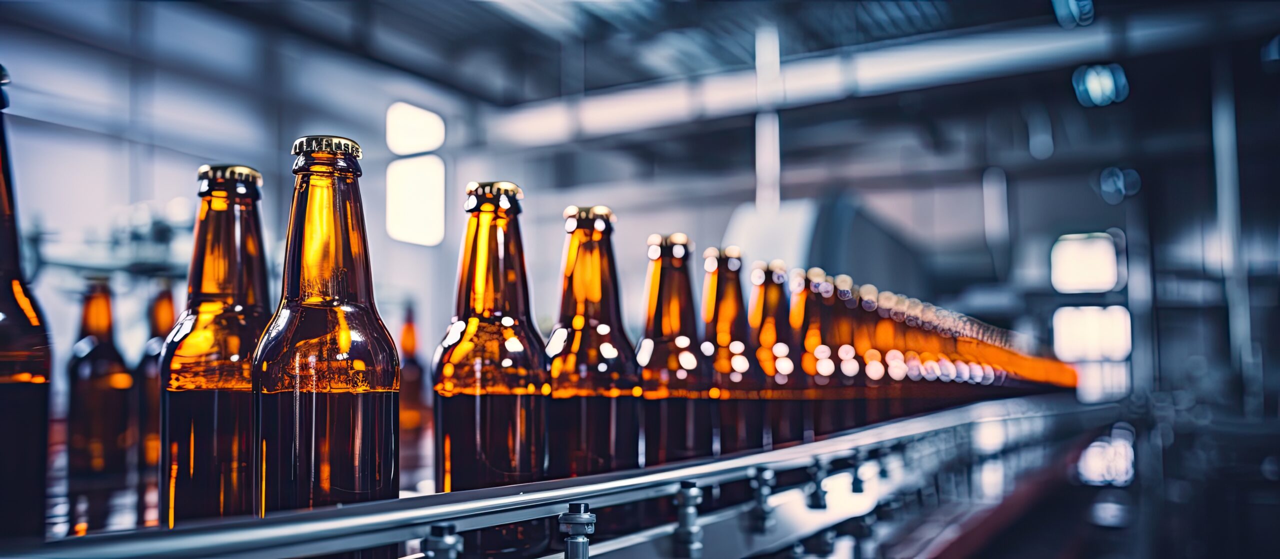
Safeguard brewing operations with cryogenic supports, variable spring hangers and constant supports.

Why is Cold Chain Management the Most Critical Factor in Brewery Quality Control?

In the brewing world, “fresh” isn’t just a marketing buzzword; it’s a biological requirement. From the moment a beer finishes fermentation to the second it hits the consumer’s glass, temperature is the primary guardian of flavor.

The cold chain, the uninterrupted series of temperature-controlled storage and distribution activities, is where a brewery’s reputation is either solidified or lost. For modern breweries, managing this chain isn’t just about refrigerated trucks; it starts deep within the facility’s infrastructure, specifically in the complex network of chilled glycol lines and stainless-steel piping.

How Does Thermal Fluctuation Impact Chemical Stability and Shelf Life?

Beer is a volatile solution of proteins, esters, and hop compounds. When the cold chain is compromised, several chemical “dominoes” begin to fall:

  • Oxidation Acceleration: Chemical reactions roughly double in speed for every 10°C (18°F) increase in temperature. Warmth accelerates the development of trans-2-nonenal, the compound responsible for that dreaded “cardboard” off-flavor.
  • Microbial Spoilage: While alcohol and hops provide some protection, certain lactic acid bacteria thrive in warmer environments, leading to souring or “ropey” textures in non-pasteurized craft products.
  • CO2 Solubility Issues: As temperatures rise, carbon dioxide becomes less soluble in liquid. This creates “breakout” in the lines, leading to excessive foaming, inconsistent pours, and significant product waste at the tap or canning line.

The Infrastructure Gap: Where Most Cold Chains Fail

Many breweries focus on their walk-in coolers but ignore the “transit” areas of their facility. If your glycol lines are poorly insulated or if your piping supports are creating thermal bridges, you are bleeding energy and risking temperature spikes before the beer even leaves the building.

What Are the Technical Requirements for Maintaining a High-Performance Brewery Cold Chain?

To maintain a “True Cold” environment, brewery engineers must look beyond the thermostat and examine the mechanical integrity of their cooling systems.

1. Eliminating Thermal Bridging

Standard metal pipe hangers can act as thermal conductors, pulling heat from the environment directly into your chilled lines. Using pre-insulated pipe supports—designed specifically for cryogenic or chilled applications—creates a thermal break that maintains the fluid’s internal temperature.

2. Managing Thermal Expansion and Contraction

Brewery piping undergoes constant thermal cycling. When lines move, they can chafe against supports, leading to insulation failure and condensation. Condensation is the enemy of the cold chain; it leads to mold growth and “wet” insulation, which loses its R-value entirely.

3. Precision Fluid Dynamics

The efficiency of your heat exchangers and cooling jackets depends on consistent pressure. If piping supports fail or cause “sagging” in the lines, it can lead to air pockets or uneven glycol distribution, creating “hot spots” in fermentation tanks.

Essential Engineering Solutions for the Modern Brewhouse

To address these technical challenges, Piping Technology and Products (PT&P) provides a specialized suite of hardware designed to bulletproof your refrigeration infrastructure.

High-Efficiency Insulated Supports

  • Cryogenic Supports (Cold Shoes): The gold standard for chilled glycol and ammonia refrigeration. They eliminate thermal bridging, ensuring that the cold stays inside the pipe where it belongs.
  • Pre-Insulated U-Bolt Supports: Ideal for exterior piping or areas with high humidity, these provide 360-degree insulation to prevent condensation and the energy loss associated with “sweating” pipes.

Advanced Pipe Hangers and Movement Control

  • Variable Spring Hangers: These supports balance the weight of the pipe as it moves during thermal cycles. This is critical for fermentation tank jackets and chiller connections, where rigid supports could cause mechanical fatigue.
  • Constant Supports: For long horizontal runs of chilled lines, constant supports accommodate vertical movement without shifting the load, maintaining the structural integrity of your facility.

Expansion and Vibration Mitigation

  • Rubber Expansion Joints: Perfect for pump inlets and chiller headers, these joints absorb the mechanical vibration that can lead to leaks, while also quieting the “hum” of the brewhouse.
  • Metal Bellows Expansion Joints: For dual-purpose lines or steam-based Clean-in-Place (CIP) systems, these withstand higher pressures and temperatures while allowing for safe thermal expansion.

Structural Protection

  • Wear Pads and Slide Plates: By allowing pipes to move smoothly over structural steel, these components prevent insulation abrasion, a common failure point in older breweries.

What Are the Most Common Infrastructure Challenges in Brewery Cold Chains?

Brewery Cold Chain, Food and Beverage Production: Frequently Asked Questions

1. How does thermal bridging in piping systems affect brewery energy costs? 

Thermal bridging occurs when highly conductive materials, like metal pipe hangers, create a direct path for heat to transfer from the ambient environment into your chilled glycol lines. This “heat leak” forces your chiller to work significantly harder to maintain target temperatures. By installing specialized insulated pipe supports, breweries can eliminate these bridges, reducing chiller energy consumption by 15–20% and preventing condensation that can lead to mold and structural corrosion.

2. Why is condensation on glycol lines a major risk to brewery food safety? 

Condensation on uninsulated or poorly supported pipes creates a damp environment where mold and mildew thrive. In a brewery, this microbial growth can lead to cross-contamination in the cellar or packaging areas. Furthermore, persistent moisture often leads to Corrosion Under Insulation (CUI), which can cause sudden pipe failure. Using moisture-resistant, pre-insulated pipe supports ensures the “dew point” stays outside the insulation jacket, keeping your facility dry and sanitary.

3. What role do pipe supports play in preventing glycol system leaks? 

Piping systems in a brewery are subject to constant thermal expansion and contraction as they cycle between cooling and cleaning temperatures. Rigid or inadequate supports can cause “stress points” at joints and valves, eventually leading to glycol leaks. Using variable-spring hangers and expansion joints allows the piping to move naturally without placing mechanical strain on the system, significantly extending the lifespan of your infrastructure and preventing costly product loss.

Boost Efficiency in Your Brewing Operations: Piping Technology and Products (PT&P)

At Piping Technology and Products, we understand that in the food and beverage industry, a pipe is never “just a pipe”—it is a lifeline for your product. We specialize in engineering and manufacturing high-performance components designed to mitigate thermal losses and mechanical stress.

By implementing PT&P’s engineered solutions, breweries can:

  • Reduce Energy Costs: Minimize chillers’ workload by eliminating thermal leaks and bridging.
  • Ensure Product Consistency: Maintain precise temperature control from the fermentation tank to the canning line.
  • Extend Infrastructure Lifespan: Prevent corrosion under insulation (CUI) and mechanical fatigue caused by constant thermal cycling.

Bolster and Protect Your Brewery’s Infrastructure

Don’t let a hardware oversight ruin a premium batch of beer. Whether you are scaling up to regional distribution or improving your current operations, our engineers are ready to help you design a thermal-efficient system that protects your investment in piping infrastructure.

Contact our engineering and field services team to audit your chilled line supports and improve your brewery’s operations.

Read More

Constant Spring Supports with Stainless Steel & Graphite Slide Plates

December 22, 2025

U-Type Constant Spring Supports in Texas

Type: Constant Spring Supports
Size: 35-7/16″ Height & 75-3/4″ Length
Material: A36 Carbon Steel with HDG | 304 Stainless Steel
Design: 9″ Total Travel at 979°F | Operating Load 6,183 lb.
Testing: Hydro tested at 6,744 lb.

These products are used across a wide range of industrial facilities worldwide, including petroleum refineries, renewable diesel plants, chemical processing facilities (such as propane/propylene splitter units), and power plants. PT&P has the capability to custom design and manufacture constant spring supports for specific load requirements and diverse environmental conditions. Notably, just last year we supplied similar constant spring supports carrying loads in excess of 150,000 lb for crude oil processing at one of the largest refineries in the world.

Petroleum refineries convert crude oil into products such as jet fuel, gasoline, polypropylene, polyethylene, propane, sulfur, carbon black feedstock, and diesel, which are used for transportation, heating, chemical feedstocks, power generation, renewable energy applications, and roadway paving.

Constant spring supports use a spring coil or series of coils to accommodate pipe movement from the installed (cold) condition to the operating (hot) condition. A defining feature of constant supports is that the supported load remains uniform throughout the entire deflection range, ensuring no variation in load on the piping or connected equipment.

These 200 U-Type constant spring supports with slide plates were designed for a plant in Texas. They are fabricated from A36 carbon steel with an HDG finish and are typically designed for vertical movement only. However, when there is lateral or axial movement in the piping system, slide plates can be used in conjunction with these constants. In this instance, graphite slide plates are bolted to the constant’s load flange and used with an upper slide plate manufactured from 304 stainless steel with a mirror finish. The upper slide plate can be welded to the base of a pipe shoe, trunnion, or the saddle of a pressure vessel. Each of the constant spring dimensions is 35-7/16″ in height and 75-3/4″ in length. They are designed for a piping system with 9″ of total travel at 979°F and an operating load of 6,183 lb. Each of these units were load tested to meet the hydro test load of 6,744 lb. before shipment.
Learn more about constant spring supports.

Read More

Scope Creep Prevention: Your 7-Point Checklist Before the Turnaround Clock Starts

December 18, 2025

Don't leave your project's safety and budget to chance. Invest in a comprehensive pipe stress analysis with Piping Technology and Products.

Scope Creep Prevention: Your 7-Point Checklist Before the Turnaround Clock Starts

The most effective way to avoid scope creep during your turnaround is to make it functionally impossible before the work starts. Once the Scope Freeze Date hits, every addition is a direct threat to your schedule and budget.

For turnaround managers and project engineers, here are the seven non-negotiable rules to enforce for a successful, on-time completion of the planned work.

Rule 1: Physically Verify Your MRO Inventory 

A database showing 12 units of an essential pipe guide or expansion joint doesn’t mean those items are on the shelf, accessible, or undamaged. Before the freeze date, a designated team member should physically confirm and tag each required Maintenance, Repair, and Operations (MRO) item within the scope. A scope addition resulting from a missing part is still a schedule killer.

Rule 2: Secure Final Sign-Off on Every P&ID Revision

Scope creep often hides in outdated documentation. Ensure that every single Piping and Instrumentation Diagram (P&ID), isometric drawing, and associated engineering document (including final pipe stress analysis reports) related to the planned work has been formally signed off by Engineering, Operations, and Maintenance. This ensures alignment on component types, sizes, and locations before the tools are staged.

Rule 3: Clearly Define What Qualifies as an “Emergency Change”

If everything is an emergency, nothing is. Establish strict criteria for any change request after the freeze date. The only acceptable triggers for breaking the scope should be:

  • Immediate safety hazard
  • Imminent environmental permit violation
  • Failure of an asset that prevents unit restart/integrity (e.g., a critical pipe support failure discovered upon opening a line).

Rule 4: Establish a 24-Hour Review Cycle for Field Change Requests (FCRs)

When a legitimate FCR does arise—such as the discovery of unforeseen corrosion under insulation (CUI) on a critical line—you cannot allow it to languish. Define a specific, cross-functional, or technical review board (TRB) that is mandated to approve or reject the FCR within 24 hours. Time spent waiting for approval is time lost on the schedule.

Rule 5: Perform a Site Walk with All Three Pillars: Maintenance, Operations, and Engineering

One week before the turnaround, conduct a final joint site walk.

  • Maintenance flags access issues.
  • Operations confirms isolation points.
  • Engineering (including those responsible for specialized equipment like expansion joints and high-temperature pipe supports) verifies component identification and confirms the physical reality matches the design drawings. This joint verification often reveals “known surprises” that can be scoped before the freeze.

Rule 6: Have a Pre-Approved List of Alternative Materials Ready

Sometimes, materials fail quality checks or are damaged during mobilization. To prevent a component sourcing delay from becoming a scope-addition crisis, engineering should provide a pre-approved list of acceptable alternatives for common components such as basic pipe guides, standard clamps, gaskets, and bolting. This allows site teams to quickly swap parts without triggering a formal FCR and halting work.

Rule 7: Ensure the Turnaround Manager is the Only Person Who Can Authorize Budget Exceeding the Baseline

Ultimate financial accountability must rest with one singular role. The Turnaround Manager (or designated sponsor) must have exclusive authority to authorize expenditures beyond the original scope of the budget. Decentralizing this power is the fastest route to uncontrolled cost and scope creep.

The Piping Technology Tie-In: Proactive Pipe Stress Analysis

In heavy industries, scope creep is often triggered by the condition of critical assets such as pipe supports, snubbers, and expansion joints. Unexpected degradation in these areas requires immediate, unplanned work. By following these 7 rules—primarily through diligent pre-walkdowns (Rule 5) and strict inventory management (Rule 1)—you ensure that all necessary specialized components are accounted for, ready, and properly installed, turning potential crisis additions into planned replacements. Proactive pipe stress analysis is key to defining this necessary scope early.

Ready to Optimize Your Turnaround Planning?

Talk to a PT&P engineer today about pre-outage inspection services or customizing your MRO inventory of pipe supports and expansion joints to guarantee readiness for your next turnaround.

Read More

5 Critical Signs You Need a Field Service Inspection for Pipe Supports

December 15, 2025

The Field Services Team from Piping Technology and Products can help you achieve maximum reliability and safety for your critical piping systems.

Recognizing Early Warning Signals in Critical Infrastructure

A comprehensive field service inspection is a predictive measure designed to prevent catastrophic failures in industrial piping systems. Understanding when to initiate an inspection is crucial for maintaining operational integrity. Facility managers and maintenance personnel frequently observe key indicators, such as damaged components (e.g., a broken spring), deviations in system alignment (e.g., pipe sagging), and other critical issues that can turn up in surrounding components and equipment (e.g., rotating equipment balance problems). Proactive assessment during planned shutdowns or in response to unexpected observations ensures the longevity and safety of high-pressure, high-temperature environments.

How do you know it’s time to call the experts? Piping and support systems are designed to operate reliably for decades, but constant temperature cycling, vibration, and external elements can cause problems. Catching these issues early is the difference between a planned repair and a much more expensive emergency shutdown.

Here are five critical signs that signal you need to schedule a professional field service inspection:

1. Discovery of a Broken Rod on a Spring Can

A spring can—or variable/constant effort spring hanger—is designed to manage the vertical movement of piping while providing support. When a spring rod is found broken, it signifies a total, localized failure of that support. This means the entire load previously carried by the spring is now being transferred to adjacent supports or, worse, directly onto equipment or vulnerable pipe sections.

A broken rod is an unmistakable sign that your pipe stress limits have been exceeded, requiring immediate assessment of the entire line for secondary damage.

2. Noticing Line Sagging or Piping Misalignment

Line sagging issues occur when the pipe deviates noticeably from its intended path or slope. This is a common trigger for our customers and often indicates that fixed supports (such as anchors or guides) have failed, or that variable supports (such as spring cans) are underperforming or frozen.

Piping misalignment is not just an aesthetic issue; it creates unanticipated stress points, restricts thermal movement, and can lead to water hammer or flow restriction. An inspection is necessary to diagnose the root cause and recalibrate or replace the failed components.

3. Facing Rotating Equipment Balance Problems

While rotating equipment (pumps, compressors, turbines) has its own maintenance schedule, recurring balance or vibration problems can often be traced back to the attached piping. When a piping support system fails, the resulting stress or weight shift can pull the pipe connected to the equipment’s nozzle.

This imposed stress can distort the equipment casing, leading to shaft misalignment, excessive vibration, and premature bearing failure. If you have recurring equipment issues despite regular maintenance, an inspection of the connected piping supports is essential.

4. Visible Red Flags: Rust, Corrosion, and Missing Components

A visual inspection by your in-house team may reveal critical but straightforward issues. Look for heavy rust, pitting, or corrosion on support components, especially where they interface with the pipe (contact points). Additionally, missing nuts, bolts, U-bolts, clamps, or even entire sway struts are serious concerns.

These signs of external degradation compromise the load-bearing capacity and movement functionality of the supports. A professional inspection will quantify the damage and recommend precise component replacements.

5. Experiencing Unusual Noise or Sudden Vibration

Any sudden or unexplained change in the operational characteristics of a piping system should prompt an immediate investigation. This includes:

  • Clanking or Knocking: Often indicates that pipe guides have failed and the pipe is impacting structural steel or adjacent lines.
  • Squealing or Grinding: May be a sign that a support or slide plate is frozen, preventing the pipe from moving freely as temperatures change, causing friction.
  • Excessive Vibrations: Can signify loose components or the propagation of a structural issue through the piping system.

Discovery of issues often happens during planned shutdowns or unexpected failures. If you notice any of these signs, our team offers specialized inspection services to assess the condition of your spring hangers and piping supports.

The Field Services Team at Piping Technology and Products

Expert Technicians, Real Solutions, and On-Site Support with Piping Technology’s Field Services Team

For facility managers, maintenance engineers, and plant operators who need to ensure the maximum reliability and safety of their critical piping systems, Piping Technology and Products (PT&P) provides rapid-response field inspection services. Unlike general contractors, our specialized experts diagnose hidden stress, misalignment, and potential component failures across your entire support system, leveraging 50 years of engineering experience to identify problems and provide custom-engineered solutions that minimize downtime and prevent catastrophic events.

Schedule Your Assessment with Our Field Services Team

Don’t let a minor problem turn into a major shutdown. Address these critical warning signs immediately.

Contact our Field Services team today to schedule your system assessment and secure your operations.

Read More
Top