Cryogenic Pipe Saddles with Micarta® Insulation for LNG Service

December 15, 2025

Insulated Pipe Supports for Low Temperatures

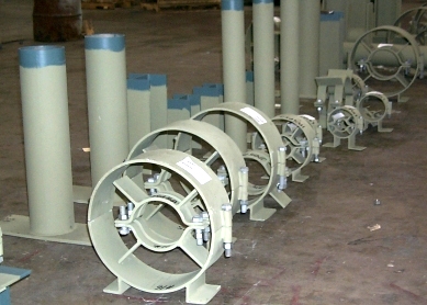
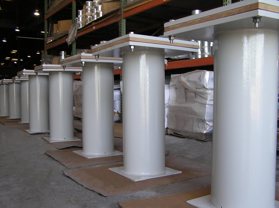
PT&P manufactured cryogenic pipe saddles for LNG transportation pipelines. These types of insulated supports have been utilized in LNG plants around the world. Insulated supports are also used on cold piping in semiconductor plants or plants that make batteries to eliminate condensation.

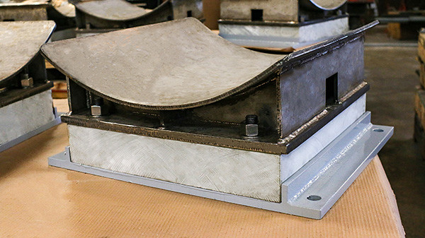
Cryogenic Pipe Saddles with Micarta® G-10 Insulation for LNG Service

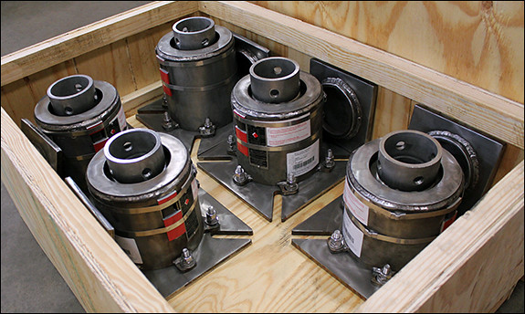
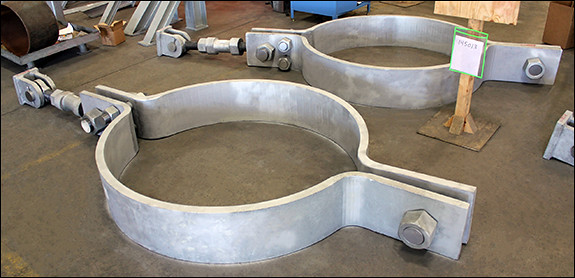
A cold shoe is a pipe support used for cryogenic applications where the transfer of cold temps from the pipeline to the surrounding steel pipe rack is not desirable. These supports can be used for temperatures down to -320° Fahrenheit.  This particular type of insulated pipe saddle assembly was fabricated with a carbon steel base plate, 304L stainless steel saddle, and an insulation block. The overall size ranges from 25” x 19” x 12-¾” to 29” x 25” x 13-3/8”. These pipe shoes were manufactured to support pipe sizes ranging in diameter from 36″ to 42″ NPS.

For additional information about Insulated Pipe Supports go to our product page.

Cryogenic Pipe Saddles Made for LNG Project

For this job, our client was a new entrant into the LNG engineering and design market space, and this was one of their capstone projects internally and for the marketplace.  Given PTP’s long history and experience concerning LNG pipe supports, we served as strategic partners in the engagement.  We identified that the client was using a pre-existing standard that underestimated the amount of Micarta® insulation thickness needed to provide adequate insulation for the facility.

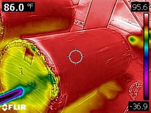
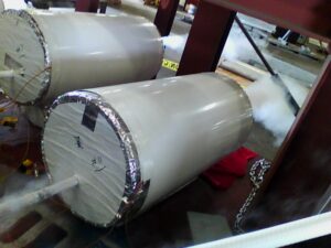
PT&P engineers recognized that the insulation was not sufficient, and we tested the existing design using a test fixture we developed to demonstrate our concern.  PT&P utilized thermal scanning (infrared technology) to measure temperature at various locations around the insulated pipe support. As a result of our tests, our client corrected the concern, saving dollars, man hours, and scheduled project completion.

pipe support thermal scanning image
pipe support on test

Our work with facilities such as these are a great example of our commitment to providing clean, affordable energy to the world.

To find additional information about our Cryogenic Pipe Saddles visit our product page.


PT&P REF. ORIGINAL POST 03092021

Read More

Choosing the Right Materials for Cold Piping in Data Centers

December 11, 2025

Invest in effective insulation for the cold piping in your data center with cold shoes from Piping Technology and Products.

Data Center Cold Piping: Preventing Condensation and CUI with the Best Insulation and Pipe Supports

In a data center, chilled water or cold piping is the lifeline of the cooling infrastructure, directly affecting thermal stability, energy efficiency, and operational uptime. The challenge is in maintaining the pipe’s low temperature while navigating high ambient humidity. Selecting the best-fit insulation material and a thermally efficient pipe support system isn’t just best practice—it’s essential to preventing devastating problems like condensation, corrosion under insulation (CUI), and system failure. This article explores the best materials and support strategies to ensure your cold piping remains a reliable, high-performance asset.

Essential Materials: Closed-Cell Insulation and Insulated Cold Shoes for Chilled Water System Reliability

The primary enemies of cold piping are condensation and thermal heat gain. When chilled water is exposed to warm, humid data center air, moisture condenses on the pipe surface if its temperature drops below the dew point.

  • Condensation: Water is corrosive, and drips can damage sensitive electronic equipment, leading to costly outages. Even more insidious, water penetration into insulation destroys its thermal performance and leads to Corrosion Under Insulation (CUI), a silent killer of piping integrity.
  • Heat Gain: Any thermal energy absorbed by the chilled water forces the chillers to work harder, dramatically increasing the facility’s Power Usage Effectiveness (PUE) and operational costs.

Effective insulation should be both a superior thermal barrier and an impenetrable vapor barrier. Let’s look at some ideal materials for cold piping and their properties.

Choosing the Right Insulation Materials

The ideal insulation for data center cold piping is a closed-cell material with extremely low thermal conductivity and low water-vapor permeability. Closed-cell structures prevent the ingress and migration of water vapor, maintaining the insulation’s integrity over its lifespan.

Material Key Characteristics Advantages: Cold Piping
Flexible Elastomeric Foam Closed-cell, high flexibility. Excellent condensation control, built-in vapor retarder, and easy installation. Most common for HVAC/chilled lines.
Phenolic Foam Rigid, predominantly closed-cell, high R-value. Superior thermal performance (very low k-value), excellent fire resistance (Class A rating), and strong mechanical strength.
Cellular Glass 100% closed-cell, inorganic, rigid. Absolutely zero water absorption, non-combustible, excellent for CUI prevention, and long-term stability.
Polyisocyanurate (PIR) Rigid foam with very low k-value. Highly effective for industrial and sub-zero temperature systems.
Fiberglass Open-cell (requires a dedicated, sealed vapor retarder). Cost-effective, but requires a flawless All Service Jacketing (ASJ) vapor barrier to be effective on cold lines; highly susceptible to moisture-related degradation if the barrier is compromised.

The Role of Specialized Pipe Supports

Even the best pipe insulation can fail at the support points. Traditional metal pipe hangers can create a thermal bridge (or “short”) when the cold pipe makes direct contact with the ambient-temperature support structure. This contact point acts as a concentrated heat-transfer area, leading to localized condensation, insulation compression, and CUI.

To solve this, cold shoes or cryogenic supports are required for cold piping systems.

Features of High-Performance Cold Shoes:

  1. Load-Bearing Insulation: These supports incorporate a high-density, high-compressive-strength insulation material (such as high-density Polyurethane Foam or Cellular Glass) between the pipe and the metal support structure. This prevents the weight of the pipe and fluid from crushing the standard insulation.
  2. Thermal Break: The support effectively separates the cold pipe from the structural steel, maintaining the integrity of the vapor barrier and preventing a thermal short. This keeps the support’s exterior surface at or near the ambient temperature, eliminating localized condensation.
  3. Vapor Barrier Integrity: The design ensures the vapor barrier is continuous around the insulation block, preventing moisture from entering the system at this critical junction.
  4. Movement Accommodation: Supports must also be designed to accommodate the pipe’s thermal expansion and contraction (e.g., resting, sliding, or guided types), ensuring the insulation and vapor barrier are not damaged by pipe movement.

Crucial Consideration: When selecting supports, ensure they are rated for the pipe’s maximum expected load and that the embedded insulation block has the required compressive strength to prevent degradation of the insulation’s thermal properties over time.

Long-Term System Performance and Maintenance

Designing for a long system lifespan requires integrating the insulation and support system from the start.

  • Pre-Insulated Pipe Supports: Some systems opt for pre-insulated pipe supports where the insulation and protective jacketing are factory-applied, ensuring uniform, high-quality, and continuous coverage, which is highly beneficial in data center cooling.
  • Thermoplastic Alternatives: Modern data centers are increasingly using enhanced thermoplastic piping (such as CPVC or Polypropylene). These materials naturally have lower thermal conductivity than metal, significantly reducing the risk of condensation and eliminating the issue of internal pipe corrosion. However, they still require proper insulation and supports.
  • Vapor Retarder Sealing: Long-term performance hinges on the proper sealing of all seams and penetrations in the vapor barrier. Even a small tear or unsealed seam can allow vapor drive, which leads to immediate thermal degradation and CUI. Use matching vapor retarder tapes and mastics as specified by the manufacturer.

By choosing the right combination of high-R-value, closed-cell insulation and specialized, load-bearing cold shoe supports, data center operators can secure a cooling infrastructure that delivers maximum efficiency, prevents system downtime, and ensures long-term reliability.

Why Choose Piping Technology and Products (PT&P)

For data center engineers and facility managers, PT&P is the trusted authority in thermal integrity. In comparison, others offer components. Piping Technology designs and manufactures insulated pipe support systems (cold shoes) that eliminate thermal shorts and guarantee a continuous vapor barrier at the most vulnerable points of your chilled water infrastructure. We don’t just hold your pipes; we secure your uptime by preventing condensation and ensuring your cooling system performs reliably under the most demanding conditions.

Protect your data center’s cooling infrastructure. Learn how to choose the proper closed-cell insulation and insulated pipe supports (cold shoes) to prevent condensation, CUI, and energy loss in cold piping systems. Our team can conduct a pipe stress analysis to help inform the selection process and protect your critical infrastructure.

Protect Critical Data Center Infrastructure: Partner with Our Experts

Don’t compromise your cooling efficiency. Contact our team for an expert consultation and custom quote on engineered cold-shoe supports and insulation solutions that ensure thermal and structural integrity for your next data center project.

Read More

Securing Your Servers: The Crucial Link Between Pipe Guides and HVAC Reliability

December 9, 2025

Pipe Guides from Piping Technology & Products help secure data center servers.

Why are specialized pipe guides critical for maintaining continuous cooling in data centers?

In data centers, every second of downtime translates directly into lost revenue. While much attention is rightly paid to power supply, network redundancy, and server technology, one often-overlooked yet utterly critical component for continuous operation lies within the HVAC (Heating, Ventilation, and Air Conditioning) infrastructure: the indispensable pipe guide.

Data centers are hot. Very hot. Rows upon rows of servers generate enormous amounts of heat that must be continuously dissipated, primarily through chilled water or refrigerant lines. These hydronic piping systems are under constant thermal stress, cycling through temperature changes that cause pipes to expand and contract. Without precise management of this movement, through pipe guides, your entire system is at risk.

Table of Water Systems in Data Centers: 

System Type
Purpose
Common Piping Materials
Key Challenges/Design Considerations
Supports & Expansion Needs
Chilled Water Systems
Circulates chilled water from central chillers or cooling towers to CRAHs or in-row cooling units.
Carbon steel, copper, HDPE (underground)
Thermal expansion, condensation control, and flow balancing
Expansion joints, spring supports, guides to manage thermal movement & vibration
Condenser Water Systems
Transfers heat from chillers to cooling towers in water-cooled setups.
Carbon steel, stainless steel
Outdoor exposure, large diameters, thermal cycling
Anchors and flexible joints to manage thermal growth & structural movement
Technical / Process Water Systems
Supports auxiliary cooling, humidification, and process functions for IT equipment.
Stainless steel, PEX
Cleanliness, corrosion resistance
Insulated supports; smaller diameters, but still require thermal isolation
Glycol / Chilled-Water Mix Systems
Prevents freezing; used in direct-to-chip or rear-door cooling loops.
Copper, stainless steel, PEX
Chemical compatibility, temperature range
Similar to chilled water systems, attention to the glycol mix impacts
Liquid Cooling / Direct-to-Chip Loops
Circulates coolant directly to chips or servers for high-density cooling.
Stainless steel, PEX, reinforced polymer tubing
Precision flow control, equipment interface sensitivity
Highly engineered supports, vibration isolation, and precise alignment
Make-Up Water & Drain Systems
Supplies and removes water for cooling towers and thermal storage.
PVC, carbon steel, stainless steel
Varies by pressure and chemistry
U-loops, flexible connectors near pumps & tanks

Why do standard pipe supports fall short in high-precision data center environments?

Traditional pipe supports, while effective in many industrial applications, often lack the nuanced engineering required for the extreme demands of a data center. Imagine a long run of chilled water piping. As cold water flows through it, the pipe contracts. When the system is offline for maintenance or experiences a load change, the pipe warms up and expands. In modern high-density environments, these lines often feed into chilled distribution units (CDUs), which require perfectly stable pressure and alignment. This constant thermal movement, if not controlled, can lead to:

  1. Excessive Stress on Connections: Flanges, welds, and fittings are the weakest points in a piping system. Uncontrolled pipe movement can exert immense bending moments and shear forces on these connections, leading to fatigue, leaks, and eventually, catastrophic failure.
  2. Misalignment of Equipment: Pumps, chillers, and heat exchangers are precision machinery. If the attached piping pulls or pushes against their nozzles due to uncontrolled expansion, it can cause misalignment, bearing wear, and premature equipment failure.
  3. Pipe “Walking” Off Supports: In severe cases, uncontrolled lateral movement can cause pipes to “walk” off their supports, leading to complete system collapse.
  4. Abrasion and Wear: Pipes rubbing against rigid, unguided supports can experience wear and tear on their outer surface, compromising their integrity over time.

This is where precision-engineered pipe guides become not just beneficial, but essential.

The Role of Pipe Guides: Guiding Movement, Preventing Failure

A pipe guide is designed to control the direction of a pipe’s thermal movement, allowing it to expand and contract axially (along its length) while preventing unwanted lateral (side-to-side) or vertical displacement. This level of control is especially vital for lines carrying technical water, where even minor leaks can jeopardize sensitive IT assets.

Fig. 6: Cylinder Pipe Guide (Spider Guide) from Piping Technology and Products

Here’s how they ensure data center HVAC uptime:

  1. Directed Thermal Movement: Guides funnel the pipe’s expansion and contraction into a predictable path. This ensures that the primary movement is absorbed by expansion joints, loops, or bellows designed for this purpose, rather than transferring the load caused by the movement into the connections of the equipment attached to the piping.
  2. Reduced Stress on Critical Components: By controlling movement, guides drastically reduce the bending moments and shear forces on pumps, valves, and other sensitive equipment connections, extending their lifespan and preventing leaks.
  3. Enhanced System Stability: They keep pipes securely positioned on their support structures, even during thermal cycles, minor seismic events, or operational vibrations, preventing displacement.
  4. Protection of Insulation: Many pipe guides are designed to accommodate and protect the pipe insulation, ensuring thermal efficiency and preventing condensation on cold lines. Often, these supports incorporate a PTFE (polytetrafluoroethylene) slide plate—a low-friction material that allows the pipe (or its insulation shield) to glide smoothly, minimizing wear and reducing the force required to move it.

Piping Technology and Products: Your Partner in HVAC Performance for Data Centers

 At Piping Technology, we understand that “good enough” is never actually good enough for data center infrastructure. We specialize in designing and manufacturing custom, high-precision pipe supports and guides engineered to your cooling systems’ exact specifications. Our solutions not only meet but exceed industry standards, providing the control necessary to manage thermal stresses and virtually eliminate the risks of pipe-related downtime. We transform potential points of failure into reliable, long-lasting assets.

Is your cooling infrastructure protected from thermal stress? Don’t leave your data center’s uptime to chance. Contact our team for a comprehensive pipe stress analysis and custom-engineered pipe guide solutions designed for maximum reliability. 

Read More

Compact Spring Supports Custom-Designed for Large Diameter Piping at a Chemical Plant

December 9, 2025

Compact Spring Supports Custom-Designed for Large Diameter Piping at a Chemical Plant

These compact spring supports were custom-designed to support large-diameter piping at a chemical plant that manufactures ethylene, propylene, butadiene, benzene, propylene oxide, styrene monomer, and other derivatives and gasoline-blending products. They are designed for large loads (13,623 lb. to 24,038 lb.) and a small confined space with limited thermal movement (from 0.2″ to 0.3″). Compact spring supports (or disc springs) minimize excessive loads on sensitive equipment, so these types of spring support the same load as a conventional variable spring but with a smaller “working range” and utilize 25-50% less space. They are ideal for locating under equipment flanges or other locations where space is limited. The housing is fabricated from A-36 carbon steel and hot-dipped galvanized to protect against corrosion. They have an installed height of 13″ – 15″ and are 21″ in diameter. The “disc springs” are engineered using stainless steel. Each assembly underwent load testing and other NDE before shipment.

PT&P REF. ORIGINAL POST 01262021

Read More

The Trunnion’s Critical Role in Pipe Support

December 2, 2025

Piping Technology and Products 35 trunnion base ell supports for a cryogenic line (1)

Understanding Trunnions: A Core Component in Industrial Pipe Stress Management

A trunnion is a critical component in industrial piping, often unsung but vital to the structural integrity and longevity of a piping system. On the surface, it may seem like a simple piece of metal. Still, its function is complex: it serves as an interface to support and/or anchor the pipe.

What is a Trunnion and How Does it Function in Pipe Support?

A trunnion is essentially a short length of pipe or solid bar that is welded perpendicularly onto the main process pipe. It is generally a rigid pipe attachment, such as a steel pipe or a structural steel member, that supports a pipe from below. Unlike a standard pipe shoe or saddle that simply rests underneath the pipe, the trunnion extends out, allowing it to connect directly to the structural steel or a secondary support member.

The trunnion’s primary function is to transfer the load (weight of the pipe, fluid, insulation, and any potential dynamic forces) from the pipe to the primary support structure.

  • Load Distribution: It concentrates the load at a specific, engineered point, distributing the weight evenly across the main pipe’s circumference at the weld joint.
  • Preventing Stress Concentration: By providing a defined attachment point, it prevents the main pipe from experiencing undue local stresses that could lead to fatigue failure.
  • Anchoring: In some configurations, trunnions can act as anchors, restricting the pipe’s movement in one or more directions (e.g., axial, lateral, or vertical movement).

Key Design Considerations for Effective Trunnion Installation

The successful use of a trunnion depends heavily on meticulous design and welding to ensure the integrity of the pipe wall. The design process must account for several factors:

1. Stress Analysis at the Weld Point

The most critical area is the trunnion-to-pipe weld connection. A specialized local stress analysis must be performed to ensure that the stress intensification factor (SIF) is acceptable.

  • The added force from the trunnion attachment can cause high, localized stresses in the main pipe wall.
  • Designers use standards such as ASME  B31.1 or B31.3 to govern allowable stresses and ensure the junction can withstand operational loads, including internal pressure, thermal expansion, and external forces.

2. Material and Dimensions

The trunnion material should be compatible with the pipe material to ensure a high-quality weld and similar thermal expansion properties.

  • Size: The trunnion size is carefully selected. A larger size spreads the load over a greater area, reducing localized stress, but it also adds more weight and can interfere with other components.
  • Length: The length must be sufficient to span the required distance from the main pipe to the support structure, often including insulation thickness.

3. Support Configuration

Trunnions often connect to different types of structural supports:

  • Slide Plates and Guides: The trunnion is frequently capped with a slide plate (made with PTFE or graphite) and placed within a pipe guide to allow for axial thermal movement while restraining lateral movement.
  • Support Shoes: When the pipe needs to be elevated, the trunnion can be attached to a secondary support shoe, further transferring the load to the primary steel.

Proper trunnion design is not just about holding the pipe up; it’s about managing dynamic movement and preventing fatigue failure over decades of operation. Choosing the right support technology, like custom-engineered supports from Piping Technology and Products, ensures these critical connections are executed flawlessly.

Is your piping system subject to extreme loads, high temperatures, or complex thermal movement? Don’t risk failure with standard supports. Contact our experts for a comprehensive pipe stress analysis and custom trunnion-based support solutions engineered for reliability.


Read More

Advanced Work Packaging (AWP) in EPC Projects: A Q&A with Lloyd Kirchner

December 1, 2025

PT&P adds value for companies that use Advanced work Packaging

Advanced Work Packaging (AWP) isn’t theory for Piping Technology and Products President and COO Lloyd Kirchner—it’s lived experience. With a background spanning EPC delivery and executive leadership as president and CEO of a construction engineering firm, Lloyd has seen firsthand how fragmented information, late materials, and unclear instructions derail field productivity. His perspective bridges engineering, procurement, and construction. With his multidisciplinary background in EPC leadership, he approaches AWP as an end-to-end discipline: plan early, reduce constraints, and hand crews complete, field-ready packages so they can finish what they start.

What is Advanced Work Packaging (AWP)?

Advanced Work Packaging (AWP) is a disciplined framework for capital project delivery that aligns engineering, procurement, and construction. Unlike traditional methods, where construction often inherits the “leftovers” of engineering schedules, AWP starts with the end in mind. It breaks the project down into manageable Work Packages—starting with Construction Work Packages (CWP) and feeding back into Engineering (EWP) and Procurement (PWP). This ensures that when a crew arrives at the job site, they have the drawings, materials, and equipment needed to perform work safely and efficiently, without idle time.

Benefits of AWP in EPC Execution

The primary advantage of AWP in Engineering, Procurement, and Construction (EPC) projects is the significant reduction in Total Installed Cost (TIC) and improved schedule predictability. By fostering interdisciplinary coordination early in the project lifecycle, AWP minimizes field rework, which is often the largest source of cost overruns. Furthermore, because AWP emphasizes “Path of Construction” planning, it enhances safety by reducing congested work areas and improves quality by ensuring that all support systems, such as pipe supports and expansion joints, are correctly staged and installed according to the engineering design.

AWP in Industrial & Energy Projects

In the industrial and energy sectors, where projects feature high-criticality piping and complex mechanical systems, AWP is a game-changer. These projects involve thousands of unique components that must be synchronized perfectly. AWP ensures that critical-path items—such as high-temperature expansion joints or custom-engineered pipe hangers—are not only procured but also tracked and delivered in the specific sequence required by the construction schedule. This “just-in-time” approach prevents the site from becoming a storage yard and keeps the focus on high-quality startup and commissioning.

Expert Insights: Q&A with Lloyd Kirchner

To better understand how these theoretical benefits translate into real-world results, we sat down with Lloyd Kirchner, a seasoned expert in EPC execution. With years of experience navigating the complexities of capital projects, Lloyd provides a boots-on-the-ground perspective on how AWP is reshaping how we think about project management and the critical role engineered-to-order components play in this framework.

Corporate headshots loydIn this Q&A, Lloyd explains how AWP emerged to solve chronic jobsite inefficiencies, breaks down its core components, and details how Piping Technology & Products supports EWPs, PWPs, and CWPs with the technical data, digital integrations, documentation, and delivery reliability that modern projects demand: plus the customization required to fit each contractor’s AWP ecosystem.

1: Tell us about AWP, how it originated, and why it was adopted.

LK: Advanced Work Packaging originated in the construction industry to address field inefficiencies where crews couldn’t finish planned work. Studies (e.g., CII) showed common blockers: missing tools, drawings, materials, instructions, or safety/quality sign-offs. The solution was to bundle everything a 5–7 person crew needs to complete 1–2 days of work into complete work packages, so crews start only what they can finish. Think “meal kit for construction,” enabled by planners and schedulers who verify readiness before release.

2: What are the major components of AWP? 

LK: The major components of AWP map to the way projects actually unfold: engineering, procurement, and construction. In engineering work packages, the goal is to decide what you’re going to build and document it so downstream teams don’t guess. That means specifications, load tables, and decisions captured in models and drawings—often BIM content—so the design is clear and clash-free before anyone buys or installs a thing. When engineering is buttoned up, procurement work packages translate that intent into vetted purchases with the appropriate documentation and timing: quotes tied to data sheets, material certifications and traceability, and realistic lead times and delivery windows that align with the schedule. 

Construction work packages then take the baton to the field. They bundle the work into scopes a crew can complete—think one to two days—with everything ready before release: installation instructions, safety and quality checks, weights and dimensions for lifts, handling requirements, and, when needed, a clear roll-down to installation work packages so the foreman can execute without surprises. When these three components are synchronized, planners can issue work that the crews can actually finish, and that’s the whole point of AWP: to organize execution from engineering through to construction. Here’s a breakdown of the major components:

  • Engineering Work Packages (EWP): engineering data, models, specs, and decisions that define what’s needed.
  • Procurement Work Packages (PWP): sourcing and buying the defined materials/equipment with the proper documentation and timing.
  • Construction Work Packages (CWP): field-ready bundles that break down scope and, when needed, roll down to Installation Work Packages (IWP) so crews can execute efficiently with no surprises.

3: How does Piping Technology and Products support EWP—Engineering Work Packages? 

LK: As a supplier, Piping Technology can help with technical data: specifications, load tables, and capacities to support proper selection. Here’s what we can deliver:

  • 2D/3D CAD and BIM: models engineers can drop directly into their 3D environments to reduce rework.
  • Bills of material and catalog content to streamline takeoffs.
  • Engineering services when requested: Piping Technology can perform pipe support engineering (e.g., based on layouts/PSA) and provide data sheets back to the engineer of record, or quote to an engineer’s spec when engineering is done on the owner/contractor side.
  • Structured digital deliverables: standard file formats compatible with common modeling/document control systems.

4: How does Piping Technology and Products support PWP—Procurement Work Packages?

LK: We can provide quotations aligned with engineering specs and data sheets, whether Piping Technology or the customer performs engineering. We can drive value by offering:

  • Material certifications and traceability (including country of origin and material test confirmations, e.g., verifying 316 vs. 304 stainless).
  • Lead times and delivery windows, with early identification of long-lead/custom items (often 6–18 weeks vs. “standard” 8–10).
  • Manufacturing status visibility and proactive updates so buyers and planners can adjust before issues hit the field.
  • Data in formats that feed AWP systems (via standard files or APIs) to reduce manual re-entry.

5: How does Piping Technology and Products support CWP—Construction Work Packages?

Aveva final 01 plant design

LK: Suppliers like PT&P can provide field-ready installation instructions and documentation for correct, predictable installations (e.g., how to install cold shoes and where to weld). We can help with the following:

  • Material attributes: weights, dimensions, and handling/field-fit constraints so sites plan offloading and lifts (forklifts/cranes) without delay.
  • Clear material identification and tracking: color-coded packaging (e.g., red shrink wrap) and RFID tagging when required to help link materials to CWPs/IWPs and find them fast.
  • Reliable delivery commitments with early alerts if anything shifts, enabling planners to issue or hold packages appropriately.
  • On-site field service support when crews need assistance installing products.
  • Optional pre-assembly/prefabrication, training, mockups, and VR/AR simulations to reduce field effort and uncertainty.

6: Lloyd, we understand that most companies have adopted their own version of AWP. Can you speak more about that customization?

LK: Absolutely. Contractors use different software and adopt AWP to varying degrees. At project kickoff, we align with each customer’s workflow, document control, and modeling ecosystem. We tailor deliverables—file formats (e.g., DWG), structured data for APIs, documentation sets, labeling/traceability methods, and even packaging—to fit their processes. 

For example, when a customer struggled to locate our materials in the warehouse for timely IWP release, we implemented distinct color-coded shrink wrap so teams could quickly identify our products and accelerate package issuance. The goal is to speak the customer’s AWP language and remove constraints before they reach the field.

Piping Technology & Products (PT&P) delivers measurable value to contractors practicing Advanced Work Packaging by aligning end-to-end with EWP, PWP, and CWP processes and the software ecosystems behind them. We provide standardized, yet easily customizable deliverables and data structures that drop cleanly into your AWP workflows and document control.

On the engineering front, we accelerate EWPs with engineering-grade inputs—specifications, load tables, capacities, BIM/CAD models, and bills of materials—that engineers can directly place into 3D models. When needed, our team performs pipe support engineering and returns data sheets to the engineer of record; when engineering is already complete, we quote precisely to your specification. Either way, you get structured digital outputs in the formats your systems require.

For procurement, we reduce risk with complete, transparent packages: quotations tied to engineering data, clear lead times and delivery windows, and flags for special fabrication and long-lead items. We support QA/QC with material certifications and full traceability, including country of origin and verification of alloy requirements, and we furnish structured data or API-ready files to minimize manual entry into your AWP tools.

In the field, we enhance both CWPs and IWPs with documentation and traceability that keep crews moving. We supply detailed installation instructions, including cold-shoe installation and weld locations, along with the practical attributes planners need: weights, dimensions, handling requirements, and field-fit constraints to plan lifts, staging, and sequencing correctly. 

To speed identification and linkage of materials to CWPs/IWPs, we enable RFID tagging when required and use distinct, clearly labeled packaging, such as red shrink wrap, so that teams can find the right items quickly. We also capture as-built updates to reflect field changes, ensuring accurate records and efficient closeout. Where it reduces risk and effort, we offer pre-assembly and prefabrication, as well as training, mockups, and VR/AR simulations.

Execution reliability ties it all together. We make delivery commitments that protect your ability to release packages on time, and we communicate proactively with manufacturing status visibility and early alerts so planners can issue, hold, or resequence work before impacts occur. By identifying long-lead or custom items early—often 6–18 weeks, rather than the “standard” 8–10—we help you set realistic schedules and align delivery windows with site readiness.

The result is a smoother, constraint-free workflow from engineering through construction, improved predictability, and field crews equipped to finish what they start. Get started with a custom quote for your project today.

Read More

Custom All Stainless Steel Variable Spring Supports for a Floating LNG Platform in Singapore

December 1, 2025

Custom All Stainless Steel Variable Spring Supports for a Floating LNG Platform in Singapore

Type: Variable Spring Supports
Material: Alloy 2205 Duplex/SAE 5160H
Design: Operating Load up to 3,597 lbs./Operating Temperatures of -15-200°F
Testing: Standard Load & Travel Tests


Variable spring supports use helical coils to carry pipe loads while accommodating vertical movement. Because coil resistance changes with compression, the supported load varies through the operating range—hence the term “variable.” These supports are commonly used under rotating equipment (pumps, compressors) to reduce transmitted vibration and mitigate piping stresses. We manufacture multiple design configurations and offer extensive customization of materials, finishes, load ranges, travel, adjustment mechanisms, travel stops, and optional monitoring instrumentation.

For this project, we supplied custom variable spring supports for an FLNG platform in Singapore. The housings were fabricated from 2205 duplex stainless to address chloride-induced corrosion, and the coils were produced from SAE 5160H for improved corrosion and fatigue resistance. Installed heights ranged from 10-3/4″ to 12-1/16″, with operating loads up to 3,597 lb. Verification included load testing at -15°F and liquid penetrant inspection of all welds. The assemblies are rated for a service temperature range of -14°F to 200°F without reduction in load capacity.

We provide a full range of pipe supports and expansion joints for offshore service, including cryogenic systems on floating platforms for LNG transfer. Our engineering and field teams have supported subsea and topside inspections, including offshore dive assessments for emergency evaluations.

Our variable spring cans are designed for FLNG applications requiring predictable load behavior under thermal expansion, vertical displacement, and dynamic operating conditions. Manufacturing capabilities cover wide load and travel ranges in compact envelopes suited to topside modular layouts. We support material selection across carbon steel, stainless, duplex, Inconel, and other alloys to meet project-specific corrosion, weight, and compatibility requirements. All units undergo in-house load testing, hydrostatic proofing where applicable, and QA/QC in accordance with offshore and global project standards. Typical applications include supports for compressors, heat exchangers, risers, separation trains, and other critical process lines.

As FLNG deployment continues to grow at ~10% annually, PT&P and its subsidiaries are supporting associated infrastructure across renewable and clean-energy sectors. We have engineered and delivered products for solar, wind, water, geothermal, bioenergy, nuclear, hydrogen, and fuel-cell projects worldwide.

Read More

Custom Designed Pipe Clamp and Sway Strut Assemblies for an Ethane Cracker Facility in Texas

November 25, 2025

Custom Designed Pipe Hanger and Pipe Clamp Assemblies for an Ethane Cracker Facility in Texas

Type: Pipe Clamp and Sway Strut Assemblies
Design: Operating load: 99,650 lb. | Temperature: 550°F
Material: A36 Carbon Steel
Size: Clamps: 149″ L x 14″ W x 2″ T | Load Bolt: 4-1/2″ | 68″ Dia. Pipe

Piping Technology & Products custom designed these pipe clamp and sway strut assemblies assemblies for an ethane cracker facility in Texas. The clamps were engineered for a 68-inch diameter pipe and utilize a bar measuring 149″ long × 14″ wide × 2″ thick. The load bolt is 4½ inches in diameter, while the inside bolts, rods, nuts, and turnbuckle are all 4 inches in diameter. The assemblies are fabricated entirely from A36 carbon steel and designed to operate at temperatures up to 550°F with a load capacity of 99,650 lb. Prior to shipment, PT&P performed a visual inspection using a sample pipe along with a full dimensional verification to ensure fit and performance. PT&P maintains an extensive inventory of pipe clamps and hardware for all types of pipe hanger and support assemblies, enabling rapid response to both standard and highly customized project needs.

Read More

Essential MSS Standards Every Piping Engineer Should Know

November 25, 2025

Mss logo

How Standards Hold Your Piping Together

For piping engineers, specifications are the bedrock of reliable and safe systems. Yet, behind every material requisition and fabrication drawing lies a crucial, often underappreciated, authority: the Manufacturers Standardization Society of the Valve and Fittings Industry (MSS). Adherence to MSS standards isn’t just a best practice; it is the non-negotiable blueprint for achieving optimal system integrity and avoiding costly field failures.

This post breaks down the core MSS standards that every piping engineer must not only know but actively implement in their daily work, ensuring your next project moves from design to commission with flawless execution.

The MSS Standards You Need to Understand

MSS SP-25: The Language of Identification

MSS SP-25, Standard Practice for Marking System for Valves, Fittings, Flanges, and Unions, is the most fundamental standard. It provides the required method of marking components, ensuring immediate and accurate identification of:

  • Manufacturer: Who made it?
  • Material: What it’s made of (e.g., A105, 316 SS).
  • Pressure/Temperature Rating: Its operational limits.
  • Size: Its nominal dimension.

Failure to verify SP-25 compliance can lead to installation errors, material mix-ups, and catastrophic failures.

MSS SP-97: The Strength of Branch Connections

When designing a branch connection (a smaller pipe joining a larger header), you must ensure adequate reinforcement. MSS SP-97, Integrally Reinforced Forged Branch Outlet Fittings—Socket Welding, Threaded, and Buttwelding Ends, sets the dimensional, tolerance, and strength requirements for these critical components, commonly known as O-lets (e.g., Weldolets, Thredolets).

  • Key Insight: SP-97 fittings are designed to provide the required area replacement for the hole cut in the header pipe, while maintaining the system’s original pressure capacity.

MSS SP-43: For the Corrosion-Resistant Systems

When working with light-wall, corrosion-resistant materials, such as those used in chemical or cryogenic service, you must reference MSS SP-43, Standard Practice for Wrought Stainless Steel Butt-Welding Fittings. This standard defines the dimensions and tolerances for stainless steel and related alloy fittings (e.g., elbows, tees, and reducers) with Schedule 5S or 10S wall thickness.

  • Why it Matters: Using the wrong dimensions here can lead to improper fit-up, requiring excessive welding or grinding, which compromises the integrity of the corrosion-resistant material.

MSS SP-58: The Support System

Pipesupportshangerscatw

Valves, pipes, and fittings are only as stable as their support structure. MSS SP-58, Pipe Hanger and Support—Materials, Design, Manufacture, Selection, Application, and Installation, is the bible for specifying pipe supports. It provides detailed guidance on:

  • Load Calculation: Determining the required capacity.
  • Material Selection: Choosing the right material for the operating environment.
  • Component Design: From rod hangers to spring supports.

Proper SP-58 application prevents excessive stress, vibration, and thermal expansion, which can drastically shorten the lifespan of your piping system. 

Piping Technology and Products: Your Guarantee of MSS Compliance

At Piping Technology and Products (PT&P), our in-house engineering and fabrication teams ensure every pipe support, expansion joint, and custom fabrication strictly adheres to the relevant MSS, ASME, and ASTM specifications. When you choose PT&P, you are not just purchasing a product; you are investing in assured compliance and minimized risk. We are your technical partner in specifying and supplying products that genuinely meet the rigorous demands of your industry.

Take Control of Your Piping Integrity Today

Every successful project starts with a bulletproof specification. Are you confident that the components you are currently sourcing meet the complete requirements of the applicable MSS standards?

  • Check Your Specs: Verify the MSS designation on your current material requisitions.
  • Consult Our Experts: Leverage our deep engineering expertise to address your complex piping challenges.

Contact our engineering and design team for a custom quote to ensure your next project is not just built, but built to last.

Read More

Excelling at Chemical Plant Design and Critical Piping Selection

November 24, 2025


PTP adds value in the design of chemical plants with custom pipe supports.


Designing a chemical plant is a monumental undertaking that requires rigorous planning, detailed engineering, and the careful selection of every component, especially the piping products that are the very lifeblood of the facility. The successful execution of a new plant relies on a structured, multi-phase process that minimizes risk, optimizes efficiency, and ensures safety and compliance. This blog post explores the key stages of chemical plant design and highlights the crucial role of different piping products in bringing these complex industrial visions to life.

The Foundation of Design: Essential Project Phases

The design process for a modern chemical plant typically comprises several phases, from conceptualization to final construction. This structured approach, known as Front-End Engineering Design (FEED) or, more broadly, the Project Management Process, ensures that technical viability and financial feasibility are confirmed before committing to large capital expenditures.

Step 1: The Block Flow Diagram (BFD)

The very first step in visualizing a plant is creating the Block Flow Diagram (BFD).

This is the simplest representation of the process. It uses blocks (rectangles) to represent major equipment, operations, or process areas (e.g., Reactor, Separator, Storage Tank). Arrows indicate the general flow of materials between these blocks. The BFD focuses on the overall process scheme, material balance, and energy integration without worrying about specific mechanical details or exact piping runs. It’s a crucial early communication tool for the entire team.

Step 2: Process and Instrumentation Diagram (P&ID)

Once the BFD is approved, the design evolves into the Process and Instrumentation Diagram (P&ID). This is arguably the most crucial engineering drawing in the entire plant design process.

The P&ID provides a detailed, schematic representation of the process equipment, piping, instrumentation, and control systems. Unlike the BFD, the P&ID includes every pipe run, valve, instrument, and control loop. It shows:

  • All major and minor equipment (pumps, vessels, heat exchangers).
  • The complete piping network, showing lines, sizes, and specifications.
  • Instrumentation (sensors, transmitters, controllers, and final control elements like control valves).
  • Safety systems (relief valves, rupture discs).

Engineers use the P&ID to verify the design’s operability, safety features, and compliance with regulations. It serves as the baseline document for all subsequent detailed engineering and procurement activities.

Step 3: The Front-End Loading Team (FEL)

While not a physical drawing, the Front-End Loading (FEL) process, also sometimes called Front-End Engineering Design (FEED), is a critical organizational phase. The FEL team is an interdisciplinary group of engineers, project managers, and financial analysts responsible for defining the project scope, evaluating technical risks, estimating costs, and establishing a detailed project execution plan.

The goal of the FEL team is to “front-load” the project with sufficient detail and analysis so that the final estimated cost is highly reliable. Successful FEL completion drastically reduces the risk of costly changes and delays during the later construction phases. The P&ID and preliminary equipment specifications are key outputs of the FEL phase.

Step 4: Geometric Model (3D Model)

The final stage of visualization involves creating the Geometric Model: the complete 3D model of the entire plant. Using specialized computer-aided design (CAD) software, engineers model the exact spatial relationship of every piece of equipment, structural steel, electrical conduit, and, most importantly, the piping. The 3D model is essential for:

  • Clash Detection: Identifying interferences where pipes, steel, or equipment physically collide before construction begins.
  • Safety and Maintenance: Ensuring sufficient access for operators, maintenance personnel, and emergency response.
  • Stress Analysis: Providing accurate routing data for piping stress analysis.
  • Fabrication Spools: Generating highly accurate bills of material and isometric drawings for pipe fabrication.

Types of Piping Products in Chemical Plant Design

The piping network is the plant’s nervous system, and its components must withstand a wide range of pressures, temperatures, and corrosive environments. The correct selection of piping products is vital for plant longevity and safety.

1. Pipes and Tubing

The main conduits are typically made of carbon steel for utility services (like water and steam) or stainless steel (304/316) for corrosive chemical applications. Exotic alloys like Hastelloy or Inconel are reserved for highly aggressive environments. Size is determined by flow rate, and wall thickness (schedule) by pressure.

2. Pipe Fittings

These components change the direction or size of a pipe run:

  • Elbows (90° and 45°): Change direction.
  • Tees and Wyes: Divide the flow.
  • Reducers: Change the pipe size.
  • Flanges: Join pipes, equipment, and valves, allowing for easy disassembly. They come in various types, such as weld neck, slip-on, and blind flanges.

3. Valves

Valves control, divert, or stop the flow of process fluid. Their type depends entirely on the service:

  • Gate Valves: Used for on/off isolation (completely open or fully closed).
  • Globe Valves: Used for throttling or regulating flow.
  • Ball Valves: Provide quick shut-off and are suitable for slurry service.
  • Check Valves: Prevent backflow.
  • Relief Valves: Essential safety devices that open automatically to relieve excess pressure.

4. Pipe Hangers and Supports

These products are critical for stress management and stability. They carry the entire weight of the pipe, fluid, and insulation while also managing movement due to thermal expansion and vibration. Products include:

  • Rigid Supports: U-bolts, saddle supports, and anchor points.
  • Adjustable Supports: Threaded rods and clevis hangers.
  • Engineered Supports: Spring hangers or constant effort supports that are specifically designed to absorb significant vertical movement while maintaining a steady force on the pipe, crucial near sensitive equipment like pumps or turbines.

Key Tools in Modern Plant Design

Smart plant plant design software

The efficiency of modern plant design is mainly due to advanced software tools. The shift from 2D drafting to 3D modeling has revolutionized the industry.

  • P&ID Software: Programs such as AutoCAD P&ID and SmartPlant P&ID enable engineers to rapidly create intelligent, data-rich schematic diagrams that link directly to equipment databases.
  • 3D Modeling Suites (CAD): Tools such as AVEVA E3D (Everything3D) and SmartPlant 3D are used to create the detailed geometric model. These platforms are the engine of clash detection and are used to produce all fabrication drawings.
  • Pipe Stress Analysis Software: Specialized tools such as CAESAR II are used to model complex piping systems mathematically. They calculate the forces and moments acting on pipes and equipment nozzles under various operating conditions (e.g., hot/cold, wind, seismic loads), ensuring the proper specification of pipe supports and preventing mechanical failure.

The Critical Role of Pipe Supports in Plant Integrity

 The selection and installation of pipe hangers and supports is a frequently underestimated element of plant design. Poorly specified supports can lead to excessive equipment stress, fatigue-related pipe failure, and costly downtime. Engineers rely on sophisticated analysis to select supports that can withstand static weight, dynamic loads (such as wind and surge), and, most critically, the substantial movement caused by thermal expansion and contraction. High-quality, engineered supports are an investment in the plant’s long-term operational health and safety profile.

 Piping Technology & Products: Your Partner in Engineered Support Solutions

At the center of plant design and operations is the need for specialized piping components. Piping Technology understands that standard catalog products are often insufficient for the extreme demands of chemical processing. We engineer and manufacture custom supports, expansion joints, and pulsation dampeners built to the exact specifications of your P&IDs and stress analysis reports. Our focus is on mitigating the risks associated with corrosive environments and high cyclic stresses, ensuring the lifespan of your most critical infrastructure.

Our teams provide custom-engineered pipe hangers, supports, and specialty components that improve the performance of your chemical plant. We move beyond standard practices to deliver precision-fabricated solutions that withstand extreme thermal expansion and corrosive environments. Set up time with our field survey and inspection teams, and get started with a full review of your plant’s piping infrastructure.


Read More
Top